Assignment 5
23.2.2017
3D Scanning and Printing
Test the design rules for your printer(s) (group project).
Design and 3D print an object (small, few cm) that could not be made
subtractively.
3D scan an object (and optionally print it).
Learning outcomes:
Identify the advantages and limitations of 3D printing and scanning
technology.
Apply design methods and production processes to show your
understanding.
Have you:
Described what you learned by testing the 3D printers.
Shown how you designed and made your object and explained why it
could not be made subtractively.
Scanned an object.
Outlined problems and how you fixed them.
Included your design files and ‘hero shot’ photos of the scan and
the final object.
3D scanning
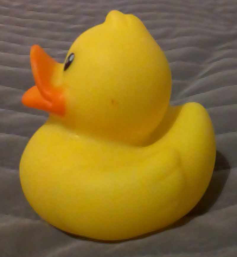
My fist attempt to scan a 3D form was this duck. It's height was 6
cm.
At first, I used Sense 3D scanner from 3D systems. I had
problems with software. The scanner was 1st generation device and I
must use Windows 7 computer to load proper software to my Windows 10
computer.
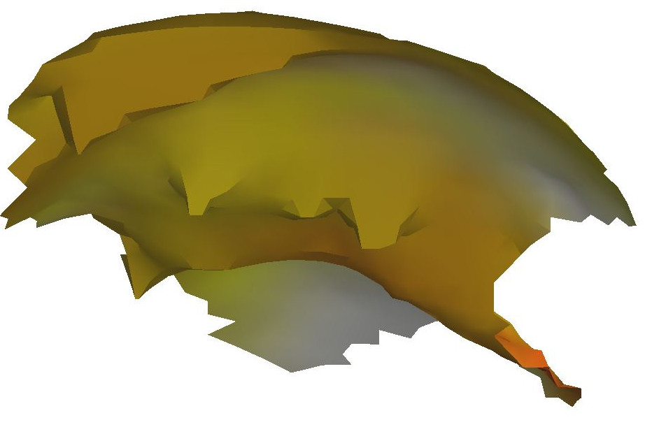
The result was here. I scanned many times. I used rotating seat,
that I rotated by hand. Also, I used camera tripod to keep scanner
fixed in place. Maybe, the object was too small. Scanning distance
and all other settings might be in order.
Then, I used also professional DPI-7 3D scanner from
DotProduct LLC. It uses PrimeSense scanning unit.
I scanned an electric drill. And, I used Dot3D viewing software from
DotProduct LLC.
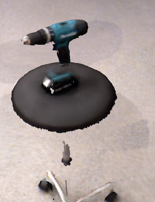
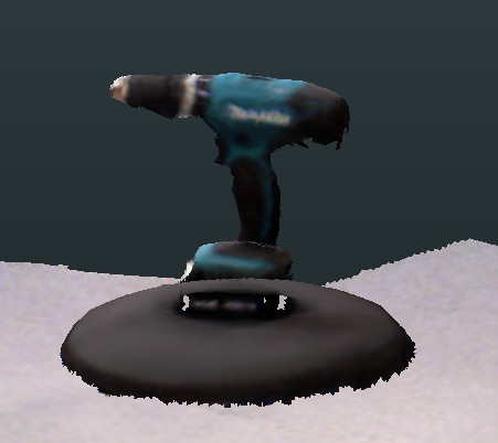
The drill located at top of rotating chair. I walked around the
object about one turn. I loaded my a scene as sample.dp file
to my computer via USB port.
Then, I used Dot3D software and done some optimizing.
Results are beautiful. Some CAD programs, such as Autodesk ReCap and
Rhino 3D can use the data for modeling. I couldn't produce stl file,
however, by Dot3D software.
3D printing
Also, I designed a model that cannot produce by subtractive way. It
was hollow part as like an egg. I tried avoid any structures inside
the part due to the egg form.
And, inside it was the second part, small ball with an arm. It is
simply impossible to use other methods to do these parts.
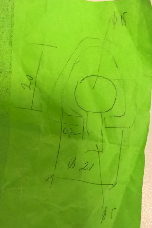 I modeled it by Siemens NX11, at
first I sketched the half of outline, then I made an offset curve
with distance of 2 mm.
I modeled it by Siemens NX11, at
first I sketched the half of outline, then I made an offset curve
with distance of 2 mm.
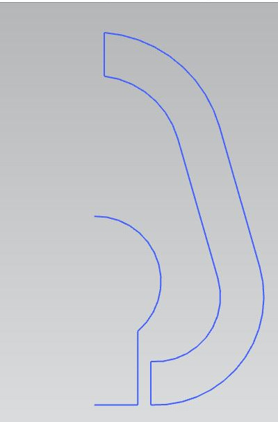
And then, I sketched the inner body, half of the ball and the
arm, similar way as earlier.
Then, closed the outer outline curves by lines above and below.
Therefore, there might exist holes up and down.
Upper hole is for emptying the liquid inside and lower hole to fix
the inner body during printing.
Finally, I revolved the all geometry.
Dimensions changed a little compared to hand made sketch. I exported
my model as .stl file by settings of triangle tolerance as 0.01 and
adjacency tolerance as 0.01.
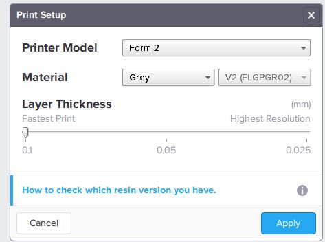
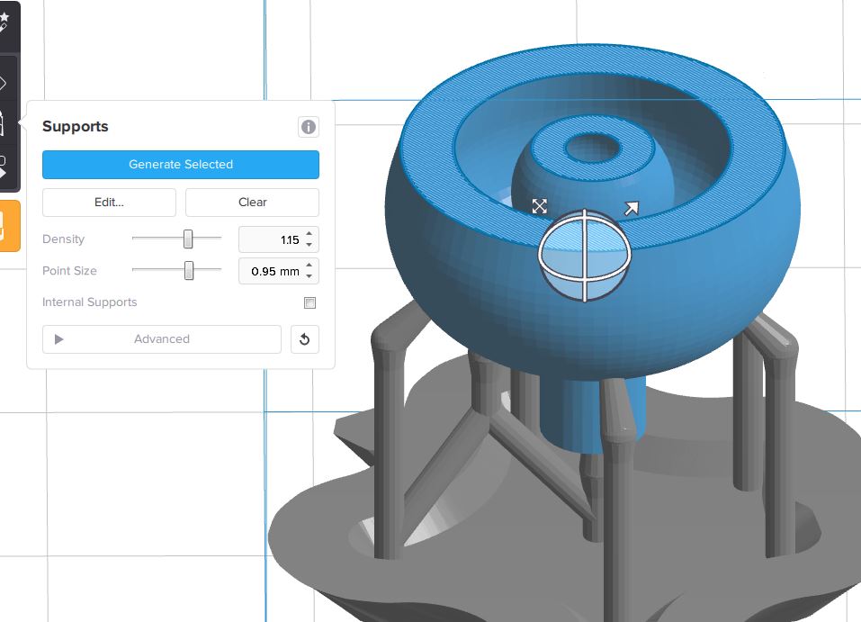
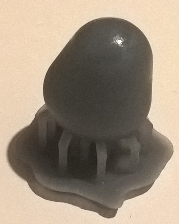
I printed it using Form 2 printer from Formlabs. Printer settings were
following: Grey V2 (FLGPGR02) material, layer thickness 0.1 mm,
density 1.15, point size 0.95 mm and without internal supports.
Printing method is stereolithography. and it's liquid is dangerous.
I opened the cap of resin cartridge before printing and checked the
resin tank bottom is clear. Then I started printing. After printing
I must wear gloves and prevent dripping while any transferring. I
must remove my part and drop it in two rinse buckets filled by 90
% isopropyl alcohol and leave each for 10 minutes. Finally, I
must clean build platform by isopropyl and remember to close the
printer cover.
Printing failed, however. There was only splotch bottom the resin
tank. Why, there found worn-out place in the middle of reservoir
tank bottom.
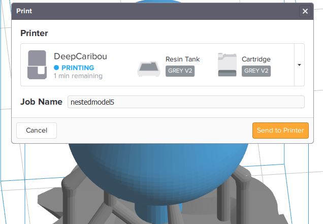
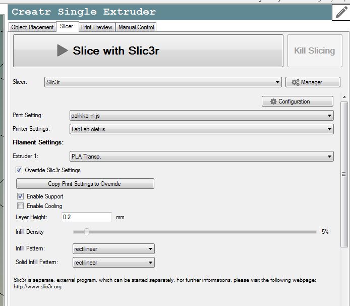
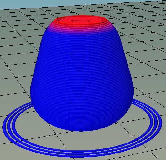
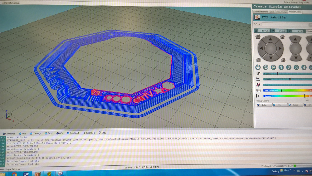
I made the second printing by Leapfrog Creator printer with
Repetier Host V1.6.2 software. The printed model was same, but the
arm was shorter. I sliced my model and computed paths for the
printer head.
I used Slic3r slicer and used default settings, but layer height was
0.2 mm and infill density 5%.
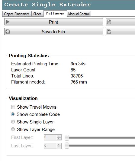
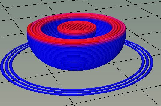
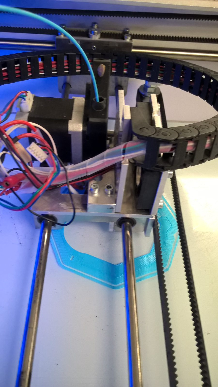
Filament material was PLA Ø1,75 mm and neutral color. And, here are
some pictures from control software. They show progress of the
printing.
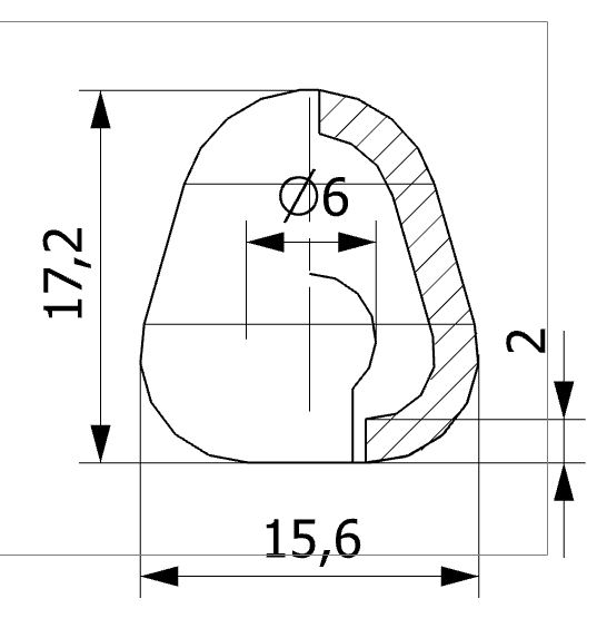
Following drawing shows dimensions and the form of my model. A small
ball with an arm locates inside an "egg". Egg form minimizes the
need of structures inside.
I started printing by Connect and Run job buttons.
It was so easy.
This printing succeeded. Finally, I detached the inner part by
pushing it inside. It rattles, when I shake it. I measured main
dimensions also. The height is 16.9 mm and width 15.5 mm.
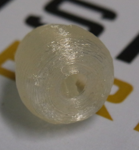
As third printing, I tried again Form 2. I removed gently the
splotch from the bottom of resin tank. I printed again, but only the
outer part and succeeded.
Again, I measured main dimensions. The height was 17.5 mm and width
15.6 mm.
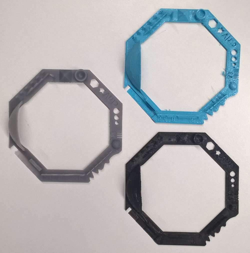
Group work
As a group work we printed a sample by three different devices. Our
group included Eino Antikainen, Yrjö Louhisalmi, Jari Pakarinen,
Mikko Toivonen,
Iván Sánchez milara and Nataliya Shevchuk. One of printers was
Leapfrog Creator.
Here are all three samples, the grey by Form 2, the blue
by Leapfrog and the black by Mikko's
own printer.
I done some dimensional analysis also. I downloaded the original
.stl file from
http://www.thingiverse.com/thing:1363023
and exported it in NX11 program. It opened there as facet body
and I cannot manage it as normal solid body.
Then, I opened it in 3D Builder. This is offered as standard
accessory in Windows 10 tools. There, I done following measurements.
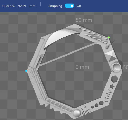
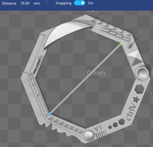
Form 2 got dimensions like 92.6 mm and 78.4 mm. Leapfrog
got dimensions like 92.2 mm and 77.8 mm. And, Mikko's
printer got dimensions like 92.5 mm and 77.5 mm.
Further, those samples inspected by eye, the Form 2 got the finest
quality. Form 2 had 0.05 mm layer thickness.
Our fourth 3D printer industry scale Stratasys Fortus 380mc was out
of order during these tests.
Some features of 3d printers in detail:
Formlabs Form 2: minimum wall thickness as supported 0.4 mm and
unsupported 0.6 mm, maximum overhang length 1.0 mm and angle 19°,
minimum clearance 0.5 mm and maximum horizontal support bridge 21
mm.
Leapfrog Creator publish only minimum wall thickness as 0.35 mm.
As a conclusion, those 3D scanners are not finished ready and
need much practicing for good results. Selected stl parameters in
CAD program, calibration of the 3D printer and selected layer
thickness may affect the printing accuracy.
My first introduction to 3D printers was about 25 years ago.
We used a stereolithography printer for medical models. Also, I have
made one digitizing arm for medical research.
At that time, Faro
arm was applied similarly. Now they produce commercial
digitizing products for industry.
My NX CAD files are here: Model_1 and
Model_2.
These also in DXF format are here: Model_1
and Model_2.
These also in STL format are here: Model_1
and Model_2.