Assignment 4
15.2.2017
Topic: Electronics production
- Make an in-circuit programmer by milling the PCB.
- Optionally, try other processes.
Learning outcomes:
- Describe the process of milling, stuffing, de-bugging and
programming.
- Demonstrate correct workflows and identify areas for
improvement if required.
Have you:
- shown how you made and programmed the board,
- explained any problems and how you fixed them,
- included a ‘hero shot’ of your board.
PCB milling
I selected my AVR ISP programmer card as Brian's
work. I impressed the simplicity, no external oscillator or
crystal. I loaded the ready made PNG files for the traces and the
board outline from Brian's page. I used tools on fabmodules.org page to
generate milling files for Roland SRM-20. At first,
I selected input format as image (.png) for traces file, selected
output format as Roland mill (.rml), selected process as PCB
traces (1/64), selected machine as SRM-20, set x0, y0 and z0 as 0,
and checked and set tool diameter as 0.4 mm and cut depth as 0.15
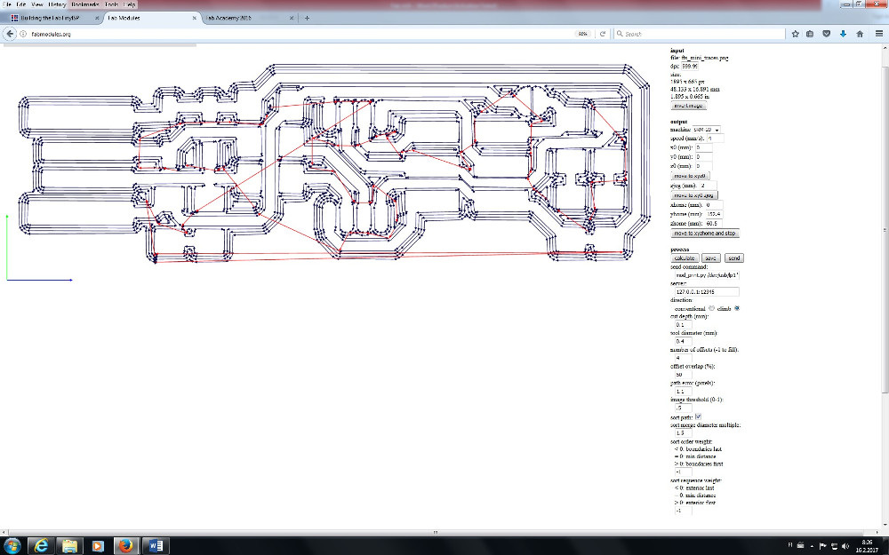
mm. Other parameters were as default. Then, I pressed calculate,
checked traces and saved the file.
I got excellent help from Dorina's
page.Here is the original BNG input file of traces.
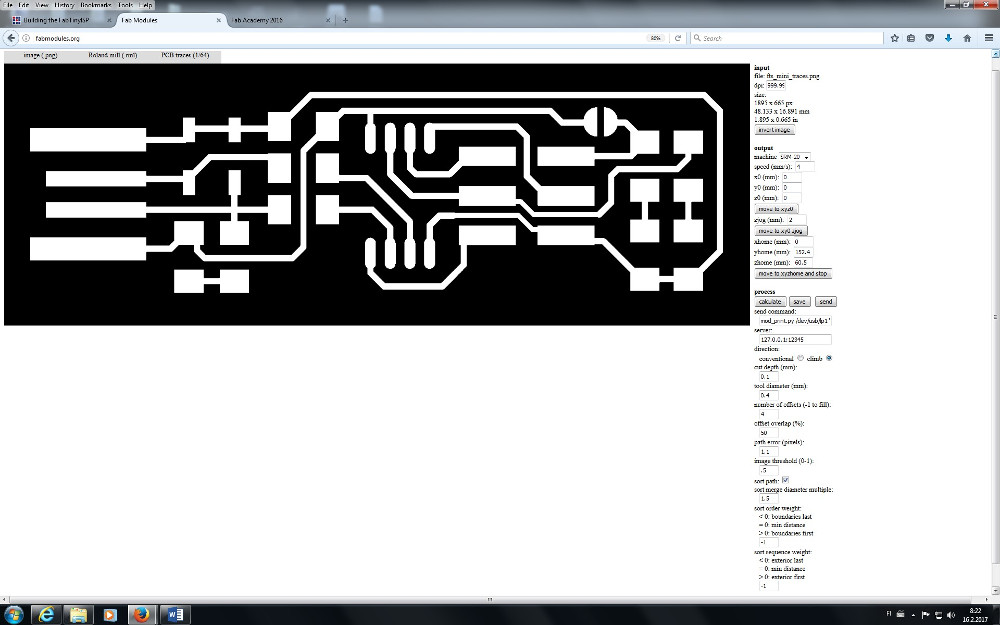
Here is the result the output file. Tool diameter is 0.4 mm
(1/64").
Similarly, I processed outlines file: selected process as
PCB outline(1/32), selected machine as SRM-20, set and checked x0,
y0 and z0 as 0, tool diameter as 0.8 mm and cut depth as 0.6 mm.
Other parameters were as default. Then, I pressed again calculate,
checked outlines and saved the file.
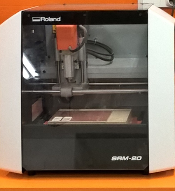
Then, I started the Roland and assembled the 1/64" bit.
Someone else was used the machine before me and there was PCB
board assembled ready in place.The board type was FR4.
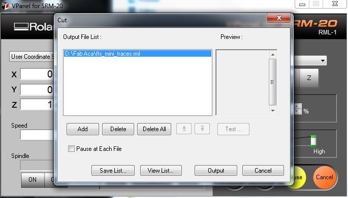
I opened the VPanel program to operate the mil, set the
X/Y and Z origins correct place and pressed the Cut button.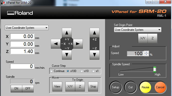
Then, I selected file I want to drive by Add button and
pressed the Output button.
Milling started well, but I noticed it didn't mill firmly. I paused
milling and looked what was wrong. The PCB board was bent upward
from the middle. Therefore, I took it out taped again very carefully
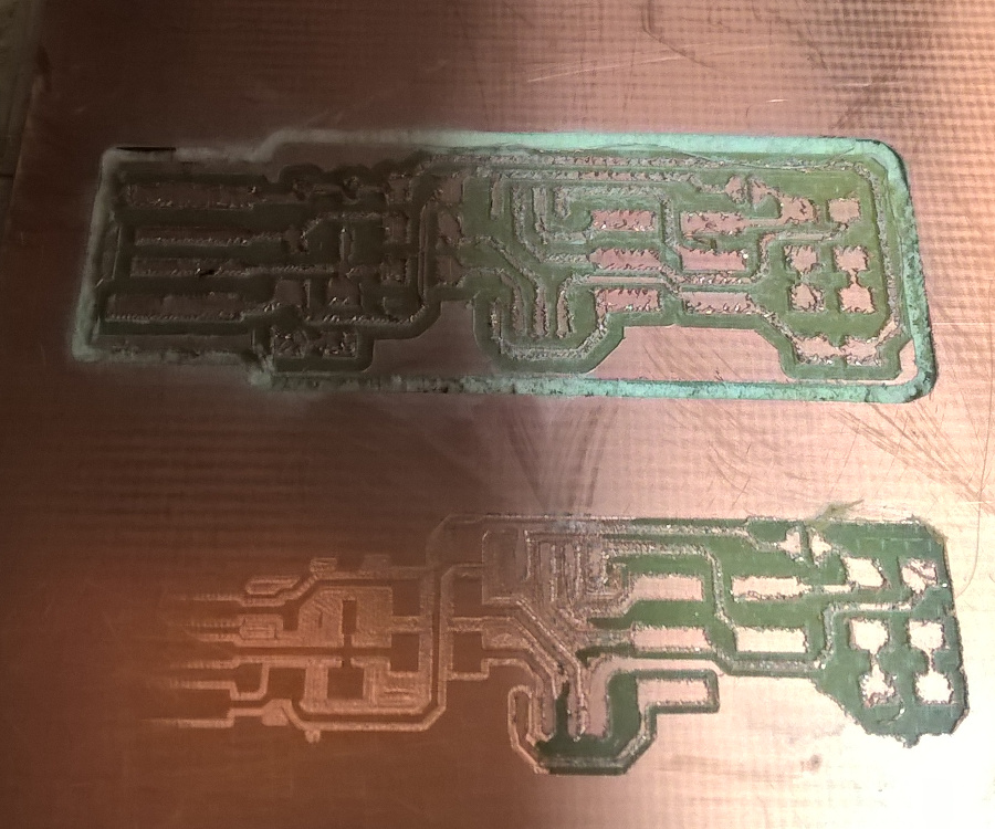
with new tape. Then, I started milling again. And, all went well. I
milled traces, changed bit as 1/32", set Z origin again and
milled outlines also. Following picture shows the first trial below
and the final milling above.
I removed the copper edge with a knife from the USB connector
side. I sandblasted firmly the board, checked it under microscope
and accepted it for further processes.
Assembling the PCB
Next step was the soldering of components. I needed following ones:
- ATtiny45 microcontroller, my version is ATtiny45V
- 1 kΩ resistors x2
- 499 Ω resistors x2
- 49 Ω resistors x2
- 3.3 V Zener diodes x2
- red and green LEDs, optional
- 100 nF capacitor, I selected 0.1 uF
- 2x3 pin header, I made it from 2x5 pin header.
I have soldered earlier many times by hand. My fist PCB milling and
soldering of surface mount components project was my garage door
opener last year.
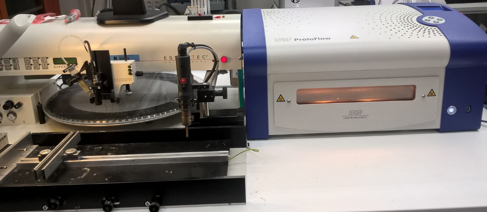
Therefore, I decided to use pick and place machine and reflow oven
again. Simply, those components are too small to my old eyes and
fingers. Results are so beautiful. And, I need still practicing.
I must use 10x magnifying loupe to place the paste and
recognize, orient and place the components. I studied cathode sides
of diodes and leds, as well as orientations to the board many times.
However, slow and careful work succeeded. The card was ready for
oven.
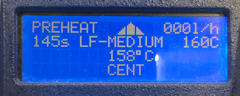
Oven was very easy to use. I opened it, prepared card place ready,
closed and selected the ramp as LF-MEDIUM.
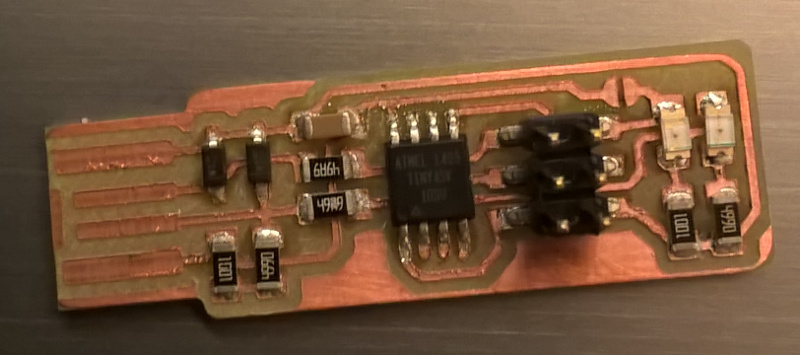
After some minutes oven opened. I put the card on tray and closed
the oven. And, the final result is here. Yet, I must solder jumper
J1 by hand.
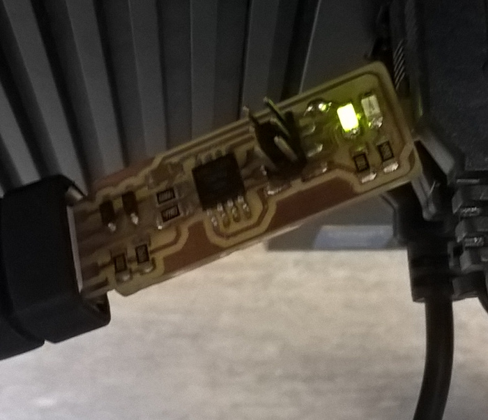
I checked connections visually by loupe and measured them by
multimeter. I have got good results. I connected the card to the USB
extension cable. It was loose there, but I used wood stick to fix
the connection. Then, I plugged it to the USB port. And, HEUREKA,
it works. Only minor damage existed. LEDs were placed in wrong
order. The green led lighted up instead of red.
Software installation
Again, I used Brian's
instructions for software installation. I checked my computers
and I found some old GNU AVR and Make installations on my desktop
computer. I tried to install new ones without success. I didn't have
privileges to install them. Therefore, I talked with others. They
recommended installing of Linux to a USB stick and further, Linux
versions of software installations.
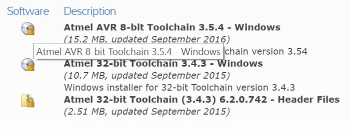
However, I decided to install required software to my laptop. It is
Windows 10 computer and Brian had good instructions for it. I
installed the Atmel GNU Toolchain (8-bit version), GNU Make,
avrdude, updated my PATH, installed drivers and made Sanity
Check as instructed.
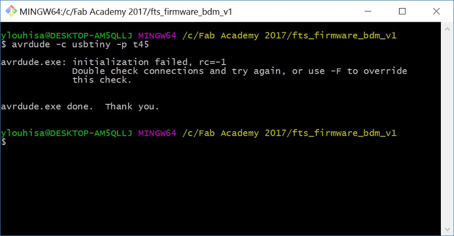
All installed well, except avrdude not. I used Atmel ICE ISP
programmer in my check and it didn't got response as proposed.
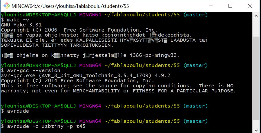
I downloaded firmware source from Brian's page and made Make successfully.
Therefore, I got the fts_firmware.hex file ready.
I installed Zadig and updated drivers, but without help.
Therefore, I decided to install Atmel Studio 7. It is big software.
Installing went well, but I couldn't use it. There exists ongoing
Atmel Tools driver problem with Windows 10.
Therefore, I used one ready installed Atmel Studio 7 in our lab's
computer to program my FAB TinyISP programmer working as a
programmer. I plugged the Atmel ICE programmer into the USB port,
plugged ISP cable from programmer to my TinyISP card and then it to
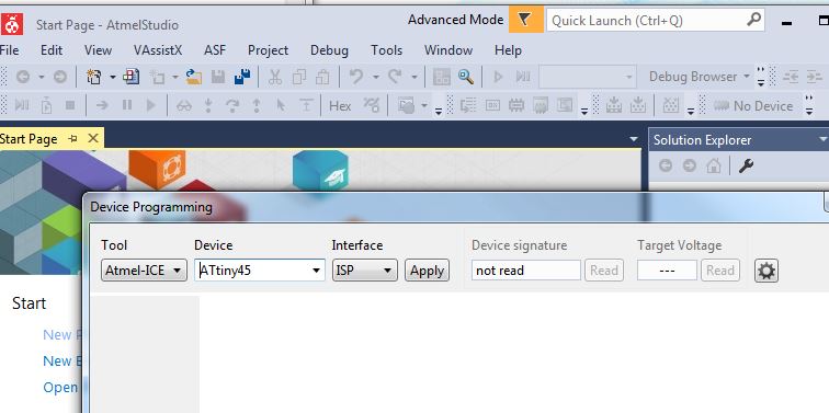
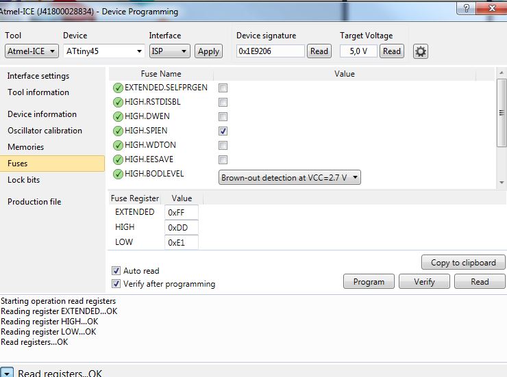
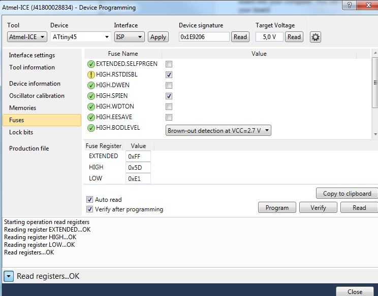
the USB port. I started Atmel Studio 7 and selected Tools >
Device Programming. I found Atmel ICE there, selected ATtiny45 as
device and ISP as interface.
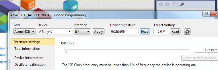
Then, I checked the target voltage and the device signature. ISP
clock setting was default 125 kHz.
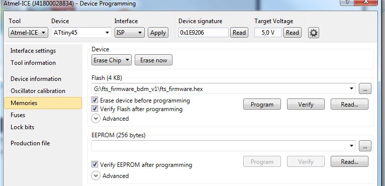
Further, I erased the chip, loaded my fts_firmware.hex
file and programmed it.
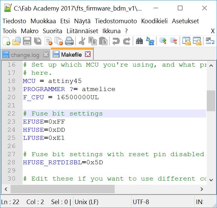
Next step was the fuses. I read the correct values from makefile
and set them to the fuse register.
Then, I unplugged programmer and my TinyISP card. And, plugged my
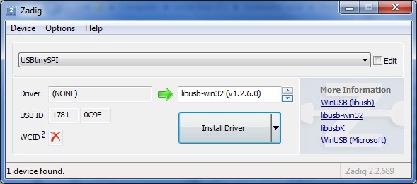
card alone to the USB port. My computer recognized it, but driver
was missing. I used Zadig program and installed libusb-win32 driver
for it.
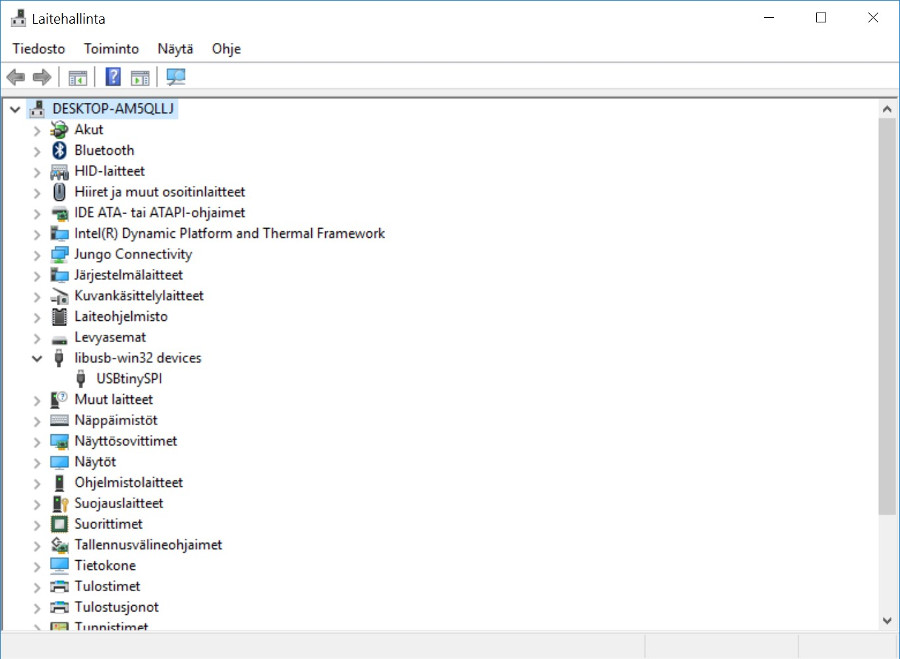
Device manager of my laptop shows my programmer as USBtinySPI under
libusb-win32 devices now. I have still problems with Atmel ICE. It
should exist under Atmel devices, when I use Atmel Studio 7.
However, AVR Dragon exists under Jungo devices as supposed.
Final work was the reset-pin setting as fuse and de-soldering
of J1 jumper.
Also, averdude works now with my FAB TinyISP.
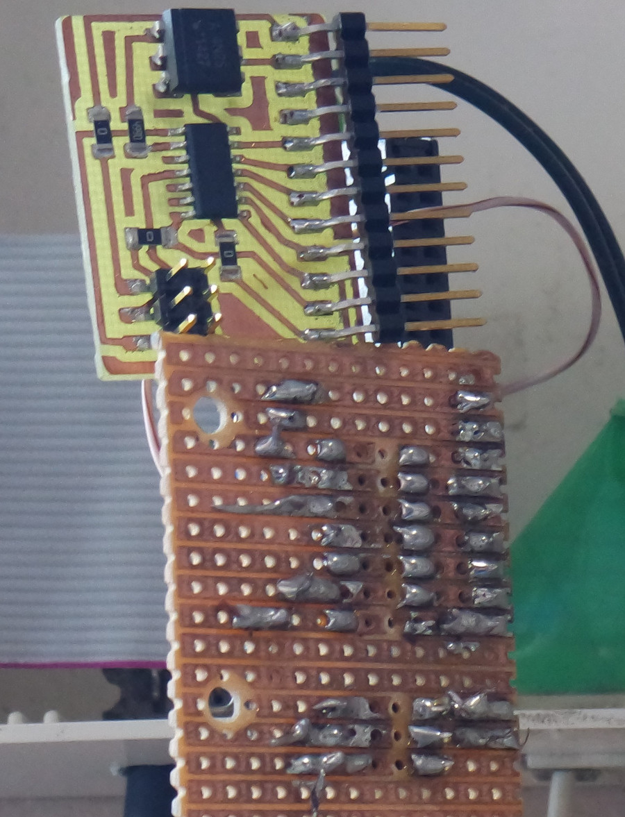
My FAB TinyISP is working now. Only minor damage existed. I placed
LEDs in wrong order. Jani predicted me that the red LED in wrong
place may damage later, because they use different dropping
resistors, red 1kΩ and green 499Ω. Red LED has 2.0 V forward voltage
and green has 3.2 V. However, I tested them and they are still
working.
Original milling files are here: fts_mini_traces.rml
and fts_mini_cut.rml .