This idea comes from my final project. I needed
communication between two microcontrollers. The first one measures
inside temperature and operate as user interface. The second one
measures battery voltage and controls motors. I needed very simple
communication between units and with minimal wires. Communication
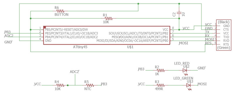
speed is low and amount of data also low. I designed new node
board which includes temperature measurement function as I
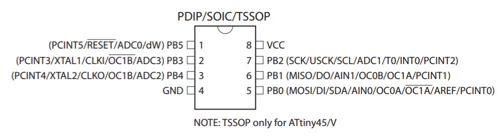
studied in Assignment 13. Here I used Attiny45 microcontroller. It
uses internal 8 MHz clock as default. I didn't change any fuse
bits.
Also, I minimized size of the board using the same connector for
programming and serial communication. TX pin serves also as SCK
pin and RX pin as MISO pin. I designed similar connection order,
VCC, GND, TX and RX, as my old board from Assignment 10. Further,
pin PB3 control both the RED led and ADC measurement. When it is
1, led lights, and when it is 0, temperature measurement circuit
grounds via PB3. Green led is controlled by pin PB0. I added also
a button to test RESET pin feature.
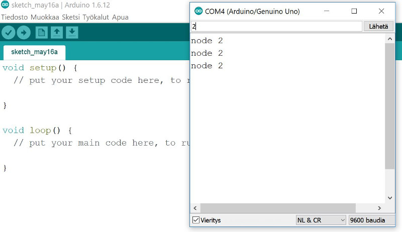
Communication is treated by serial connection via TX and RX pins
and with 9600 baud rate. The communication code originates from Neil's
hello.bus.45.c code from Fabacademy 2017 pages. I studied
the original code and made some minor changes. I set clock speed
as 8 MHz, added definition for RED led and increased the led delay
to 1 sec.
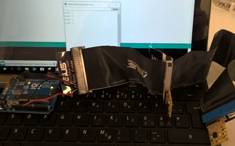
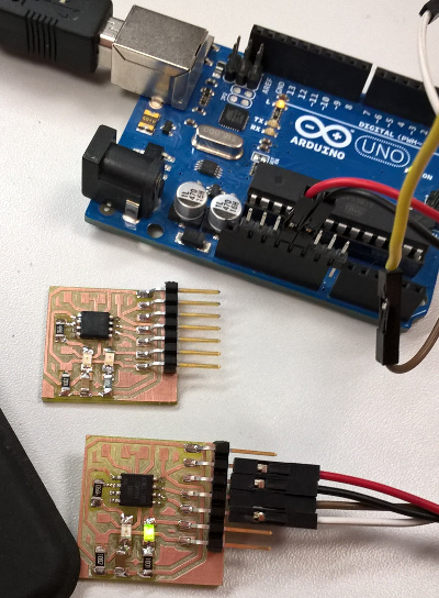 I milled and soldered by hands two node
boards, programmed them via Atmel studio 7 as earlier assignments
advised and used my Arduino for test purposes. Empty Arduino sketch
can be used as serial communication link to boards.
I milled and soldered by hands two node
boards, programmed them via Atmel studio 7 as earlier assignments
advised and used my Arduino for test purposes. Empty Arduino sketch
can be used as serial communication link to boards.