- what will it do?
- who's done what beforehand?
- what materials and components will be required?
- where will they come from?
- how much will it cost?
- what parts and systems will be made?
- what processes will be used?
- what tasks need to be completed?
- what questions need to be answered?
- what is the schedule?
- how will it be evaluated?
Idea Development
Since my current PhD studies focus on Persuasive System Design and Behavior Change Support Systems in domain of sustainability, I wanted to relate my final project to these topics. The initial idea is to create a device that helps people be more sustainable, for example, how to save reduce water consumption while showering. In the final project, I will try using as many skills learned throught the course as possible. Here is how each week contributed to the final outcome.
Week 1: Principles and Practices, Project Management

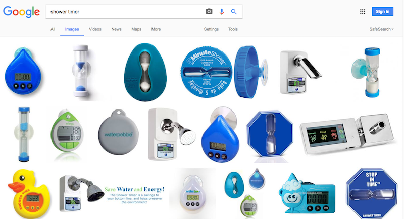
Having heard of exsisting the commercial equivalents of the shower timers, I decided to make an attempt to make my own.
In addition to formulating the idea of the final project, this week the website was built, where the project will be persented. Learning how to use the class archive and managing it with Git will helped keeping all relevant project files in one place.
Week 2: Computer-Aided Design
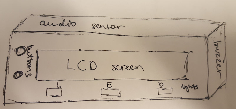
Learning about 2D and 3D softwares helped choosing tools for modelling parts of the final project, in particular the 'packaging' for the projects electronics. While familiarizing myself with computer-aided design techniques, I made several sketches of what the timer might look like. Although these designs were far from being similar to the actual outcome, this was a good excercise for developing a better understanding of what I am trying to achieve.
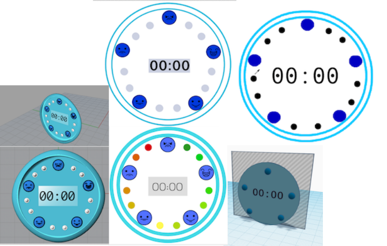
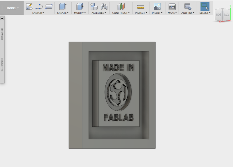
I ended up using Inkscape for 2D design of the box and creating a design for the sticker, and Fusion 360 for designing a model of the structure for attaching the timer onto something. I also used Fusion 360 for designing a 3D mold "Made in Fablab" which I could use to feature the origin of the product.

Week 3: Computer-Controlled Cutting
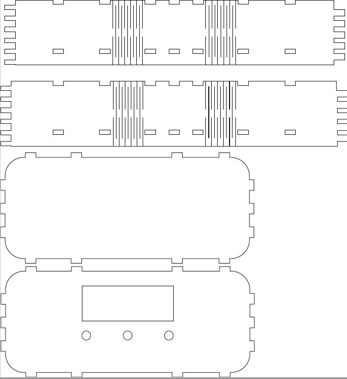
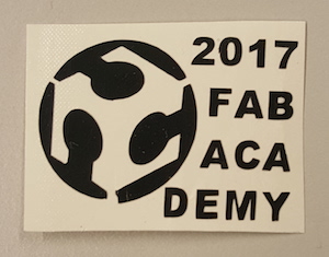
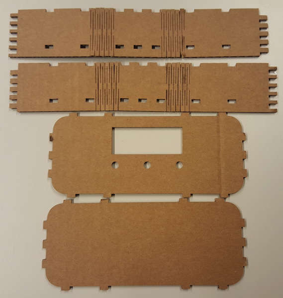
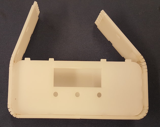
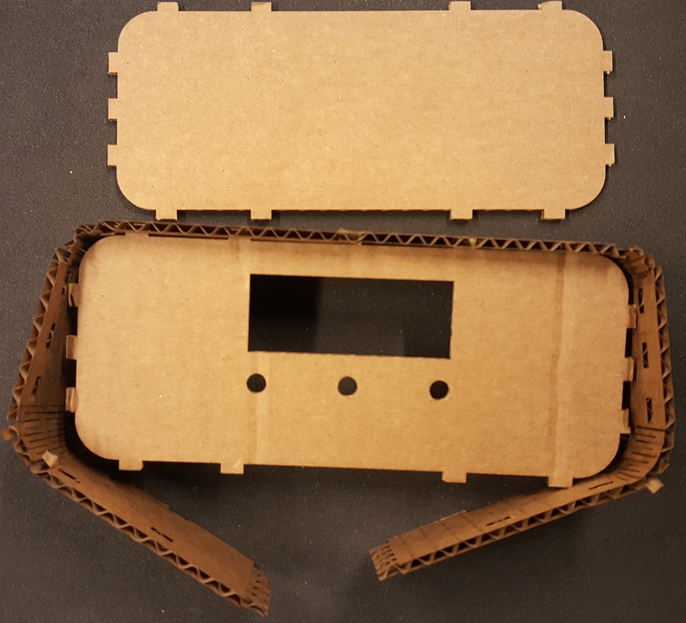
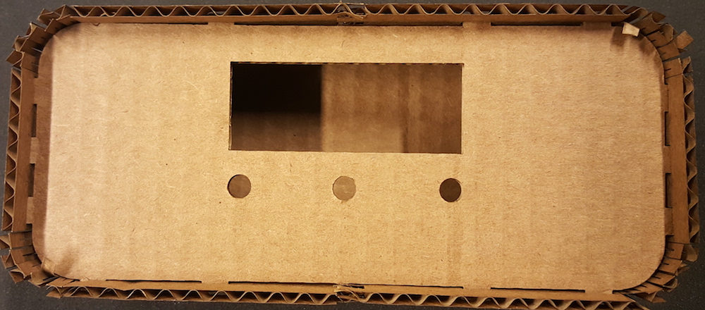
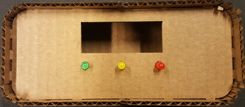
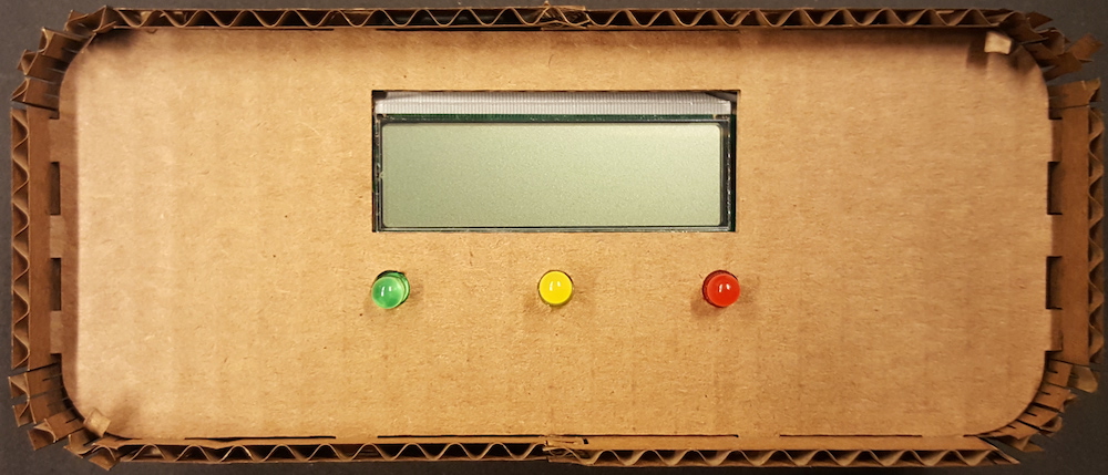
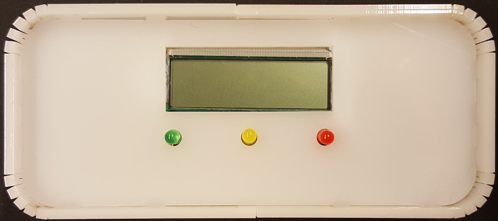
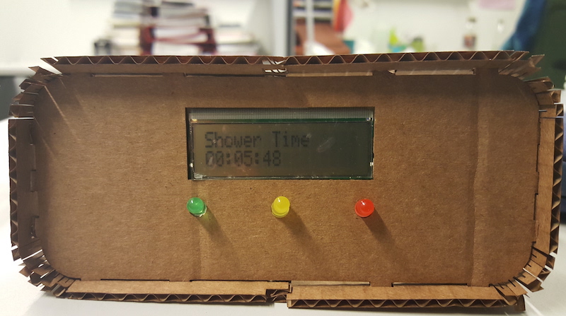
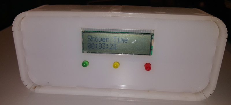
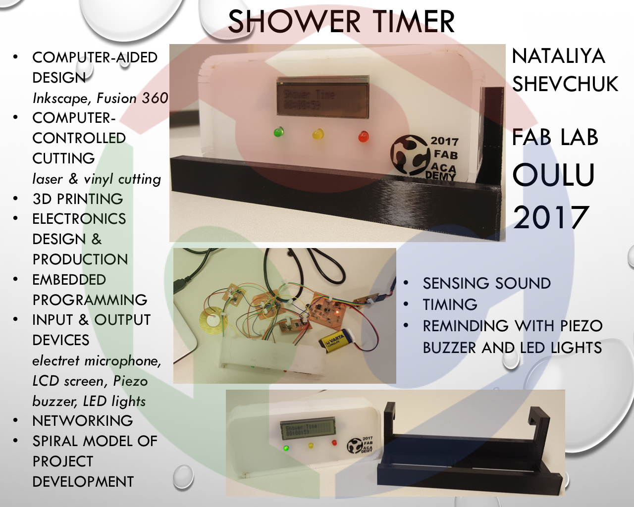
I used vinylcutting to make a sticker for the final project and a laser cutter to make the outer case for the timer. I lasercut the case both in cardboard (to test the design) and in acrylic plastic for the final version.
Week 4: Electronics Production
This week a programmer was made with which ALL of my boards made in this course were programmed. It was also a week of introduction to using fabmodules, milling and soldering.
Week 5: 3D Scanning and Printing
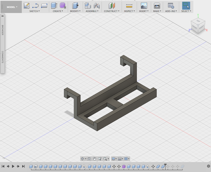
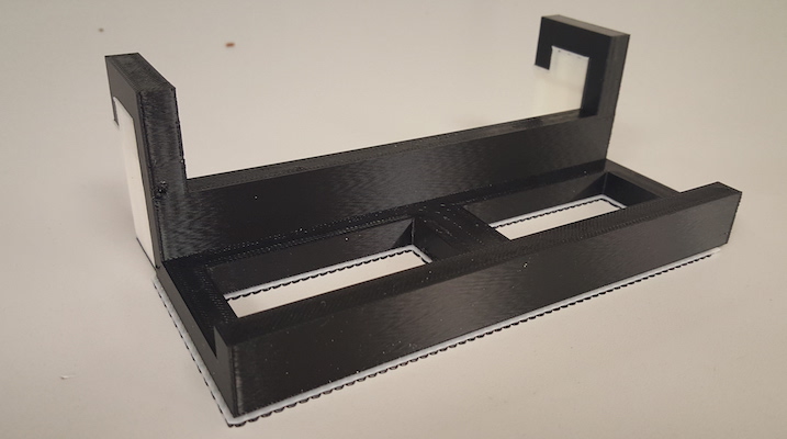
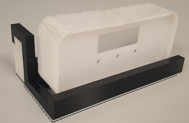
For the final project, I 3D prined a structure that would help hanging up a timer somewhere if needed. 3D scanning was fun to learn and the final project could be 3D scanned, but as there is no real need to and no extra time for that, I did not make 3D scans.
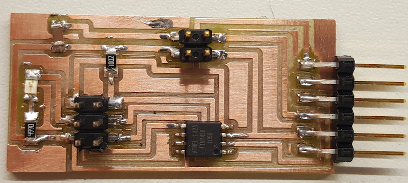
Week 6: Electronics Design
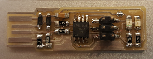
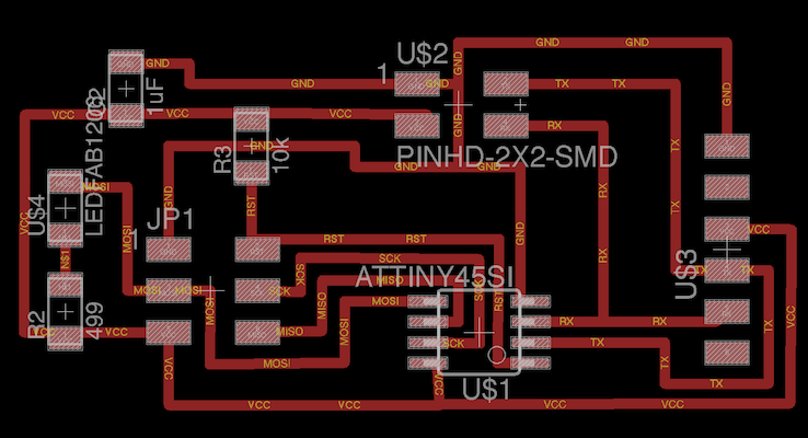
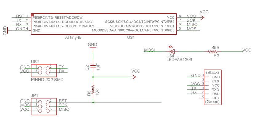
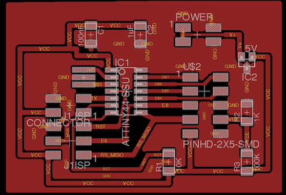
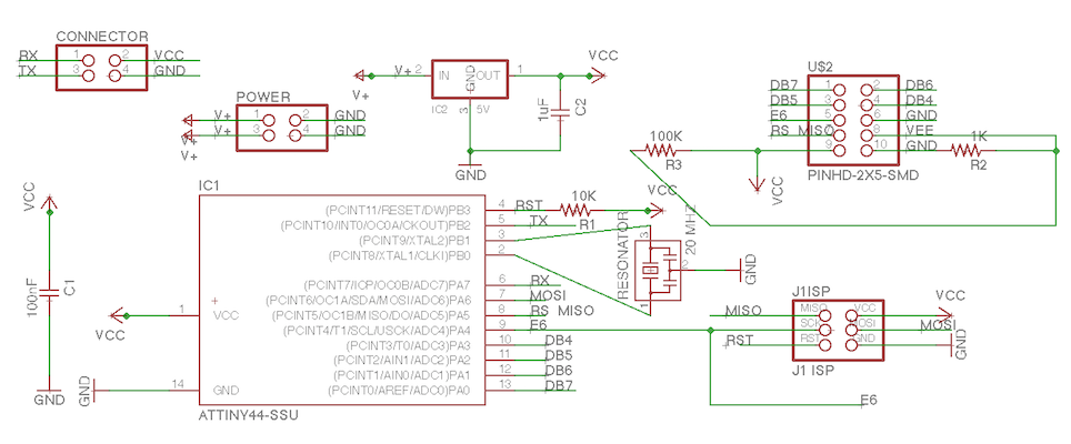
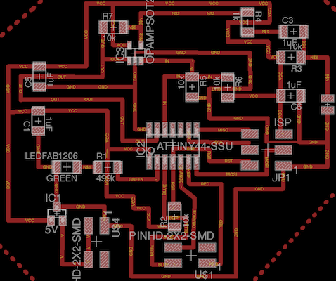
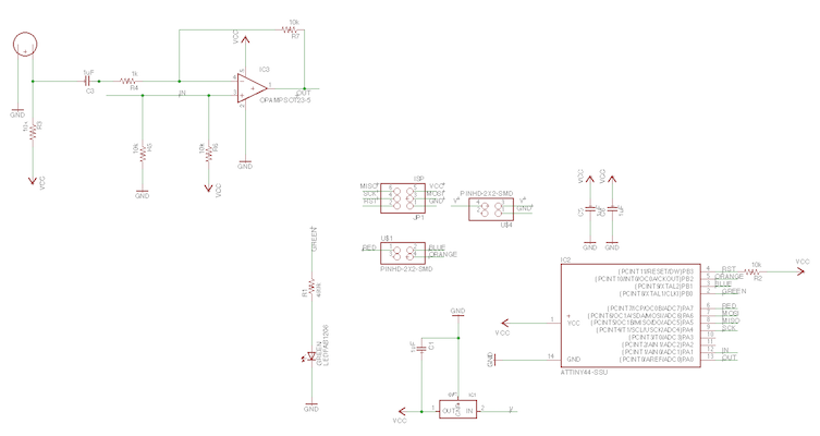
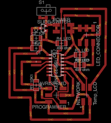
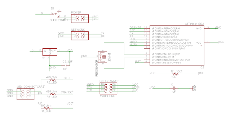
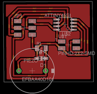
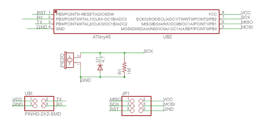
This week I learned the basics of using Eagle software, which I continued using for designing all of the boards made by me in this course. Below are schematic and board designs of the PCBs used in the final project
Week 7: Computer-Controlled Machining
A challenging week it was...In terms that it took some time to make the final assembly of the assignment. It was a good practice of making 3D designs in Fusion 360, which was used for the final project.
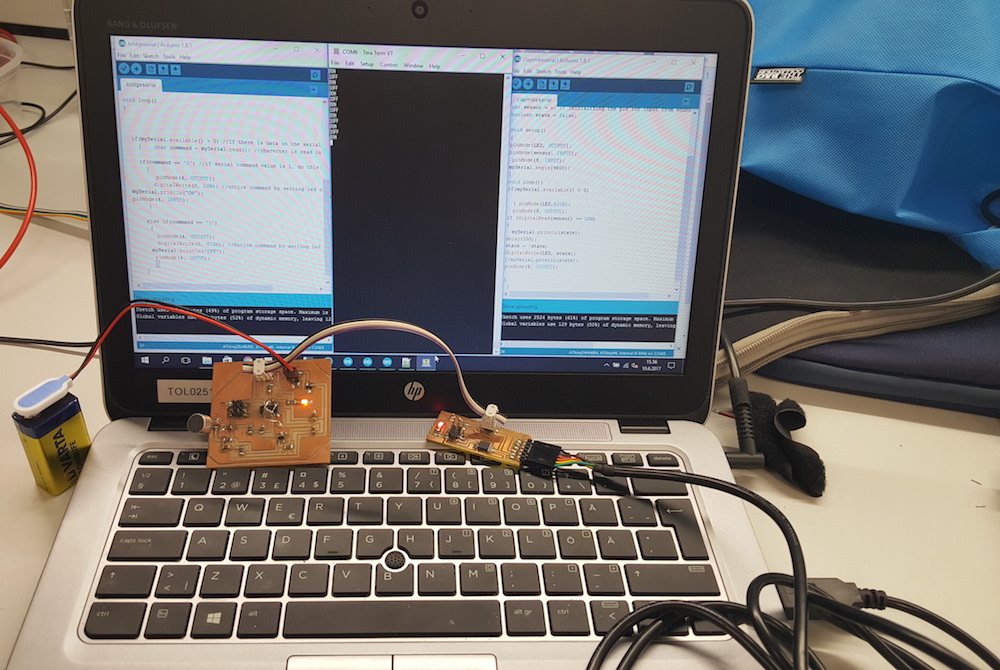
Week 8: Embedded Programming
This week involed in-depth learning of properties of microcontrollers. I focused on ATTiny44A and ATTiny45V which I ended up using in the final project. I also got acquainted with the IDE environments and decided that I will be using Arduino for the final programming.
Week 9: Mechanical Design
This week's skills helped me planning how to assemble my final project. Also based on the experiences of this week, I made a schedule for implementing the final project.
Week 10: Output Devices
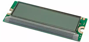
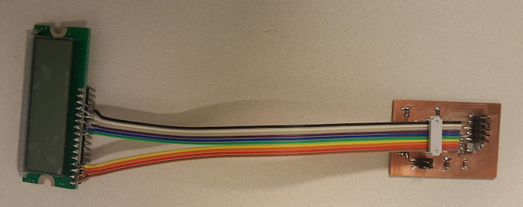
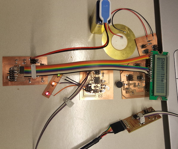
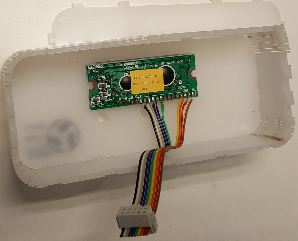
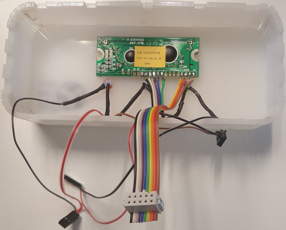
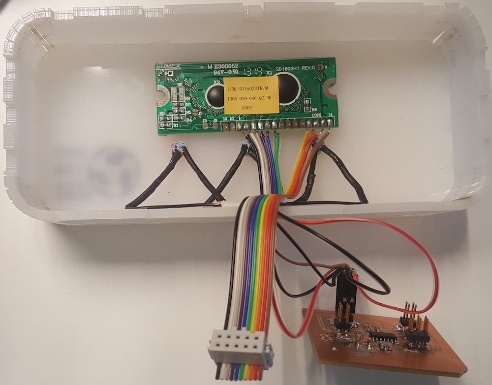
This week I practiced designing a board with the LCD screen.
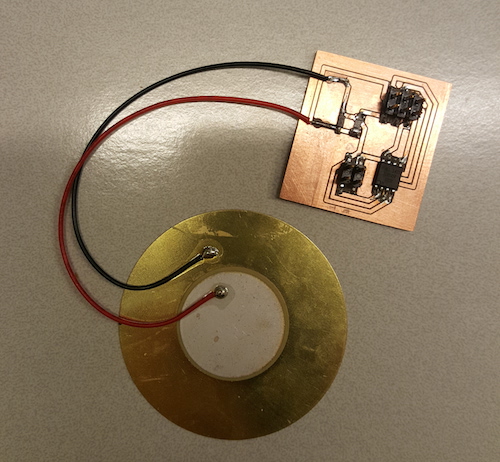
Later, I also designed a board with the piezo buzzer to be used in the final project.
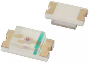
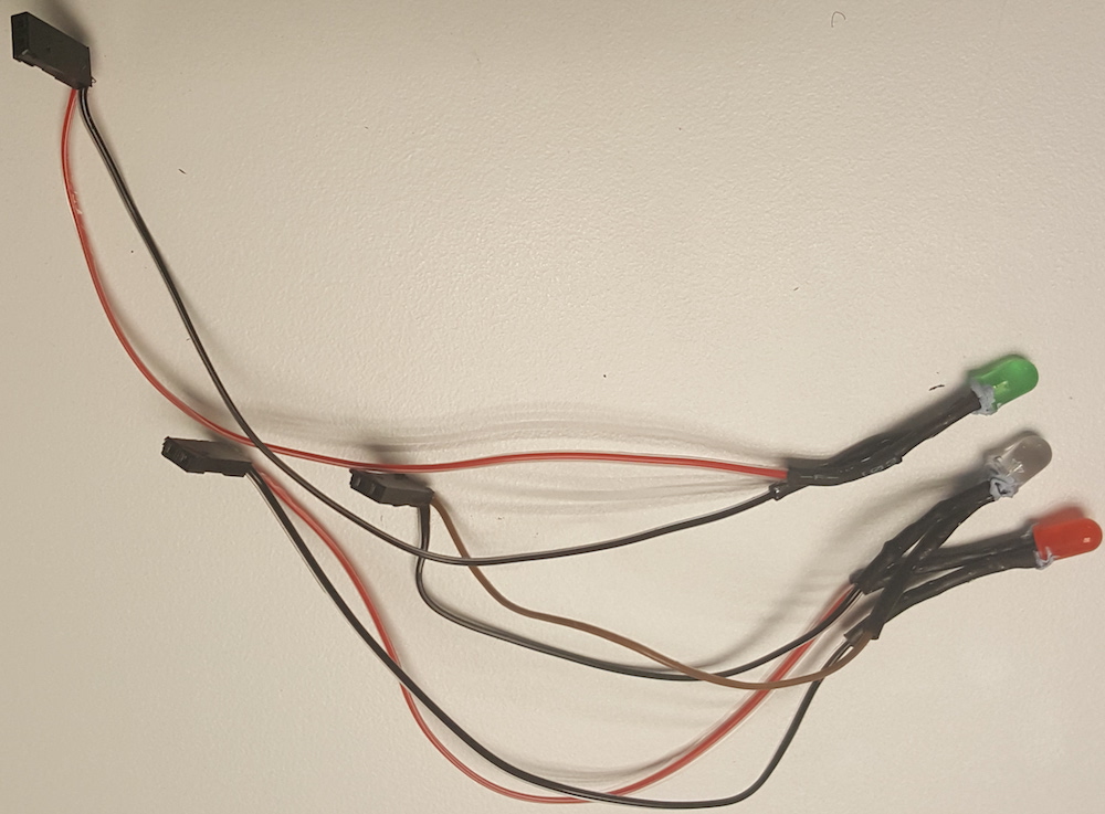
And I designed a board with the three LED lights. At the beginning I was using the SMD lights available in the Fab inventory (green, orange, and red).
I milled a small PCB to solder them onto and connect to the main board and use until I am able to refine the code for this board and ensure that the code works the way I want.

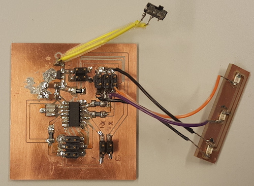
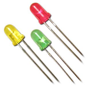
In the final design, I chose to replace them with the Arduino-type lights. Initially, I used green, yellow and red lights (thanks to Ivan for them), but eventually I had to replace the yellow one with the clear one, since the yellow stopped working and the only available I could find was a clear one. I also ended up not using the switch which I initially planned to have so I desoldered the one shown in the picture.
Week 11: Machine Design
As I was doing a major part of documentation and presentation for the group assignment, this week was a good practice for preparing materials for the final project presentation. It was also helpful to practice designing and building functional systems, recognizing opportunities for improvement and future iterations of the project idea.
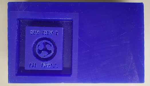
Week 12: Molding and Casting
I designed a "Made in Fablab" seal which could be used to identify items made in Fablabs. I had time to make a wax mold before the project presentation but the silicone mold and the actual cast will have to be placed on the "to-do" list for later.
Week 13: Input Devices
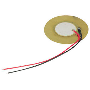
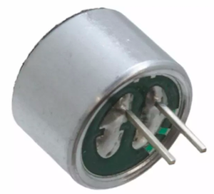
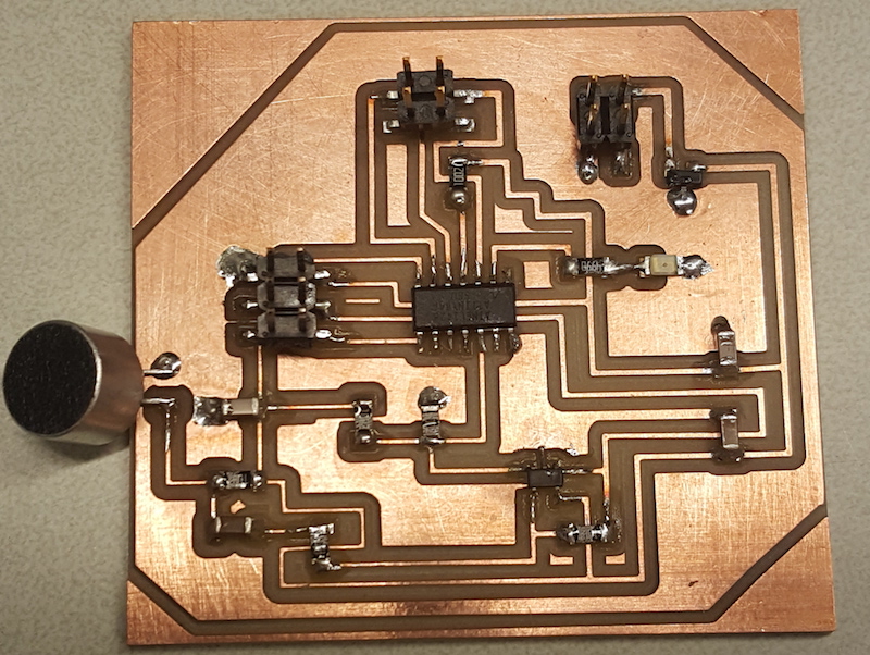
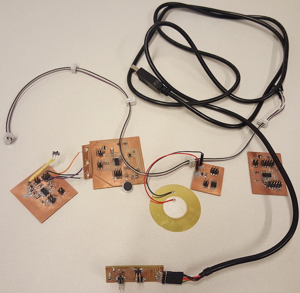
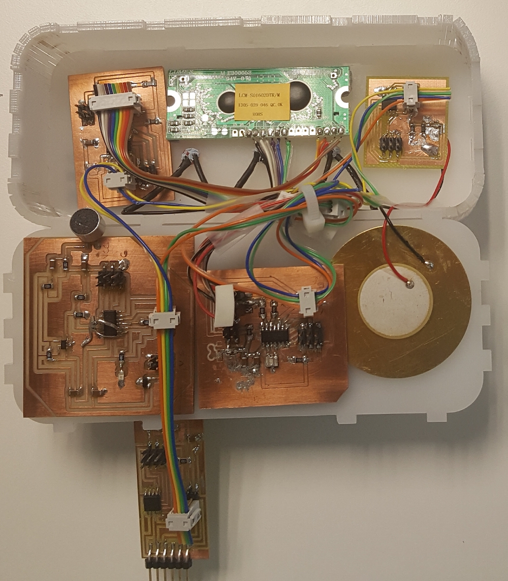
This week I designed a board with the electret microphone, which I will be a part of the final project.
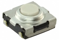
Initially, I was also planning on using buttons in the project, but ended up eliminating them from the final design.
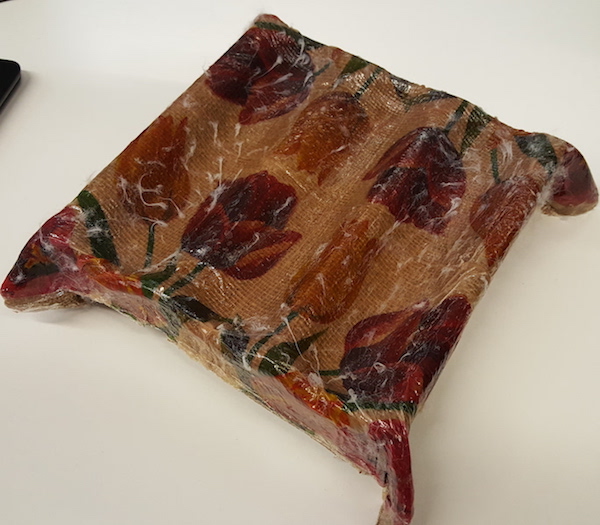
Week 14: Composites
I designed a multipurpose tray this week. Maybe I could display my final project on it? Other than that, I am not planning to make any other composites in the final assignment.
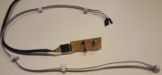
Week 15: Embedded Networking and Communication
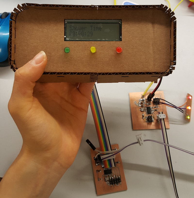
I will be using skills learned this week to establish connection among the boards from which the final assignment's systems consists. After reviewing and evaluating options, I chose to network the boards with serial bus asynchronous connection. This week, I also created the bridge board which I will need to create the connection among the boards. Next I managed to connect the sensor board with the bridge, then added the board with lights and I will be adding the LCD and the piezo board.
Week 16: Interface and Application Programming
This week helped acquire skills which I can use for the future development of the project. It would be indeed useful to implementing an app which can summarize and visualize the user data collected with the timer's sensor. Due to a tight schedule, I will not be making any applications for the final presentation of the project.
Week 17: Applications and Implications
This week provided time to summarize the final project, schedule project execution and answer crucial questions to help outline the scope of the project and develop a project plan. During this week I created a tentative bill of materials, which in the end had only minor changes. The differences between the two BOM are due to the change from teh SMD to Arduino type lights.
| Component | Quantity | Cost/Unit | Total |
|---|---|---|---|
| microcontroller ATTINY44A-SSU-ND | 3 | 1.18 | 3.54 |
| microcontroller ATTINY45V-10SU-ND | 2 | 1.23 | 2.46 |
| resonator 20.00MHZ SMD | 2 | 0.43 | 0.86 |
| zener diode 4.7 | 1 | 0.07 | 0.07 |
| electret microphone 668-1296-ND | 1 | 1.65 | 1.65 |
| op-amp AD8605ARTZREEL7CT-ND | 1 | 1.35 | 1.35 |
| regulator LM3480IM3-5.0/NOPBCT-ND | 2 | 0.32 | 0.64 |
| 1uF capacitor | 8 | 0.07 | 0.56 |
| 100nF capacitor | 1 | 0.12 | 0.12 |
| resistor 499 Ohm |
5 | 0.01 | 0.05 |
| resistor 10K Ohm | 9 | 0.01 | 0.09 |
| resistor 100K Ohm | 1 | 0.01 | 0.01 |
| resistor 1K Ohm | 2 | 0.01 | 0.02 |
| resistor 1M Ohm | 1 | 0.01 | 0.01 |
| LED Orange | 1 | 0.1 | 0.1 |
| Arduino 5mm basic LED Red | 1 | 0.13 | 0.13 |
| Arduino 5mm basic LED Green | 1 | 0.35 | 0.35 |
| Arduino 5mm basic LED Yellow | 1 | 0.35 | 0.35 |
| LCD 16X2 module | 1 | 7.06 | 7.06 |
| Piezo | 1 | 2.95 | 2.95 |
| 2X2 Pin Header | 7 | 0.66 | 4.62 |
| 2X3 Pin Header | 5 | 0.6 | 3 |
| 2X5 Pin Header | 2 | 0.67 | 1.34 |
| 9V battery | 1 | 4.88 | 4.88 |
| 9V battery snap with 2pc molded | 1 | 0.52 | 0.52 |
| 5V FTDI cable | 1 | 20 | 20 |
| 2X2 connector socket | 7 | 0.55 | 2.75 |
| 2X5 connector socket | 1 | 0.55 | 0.55 |
| Tin power socket crimp | 8 | 0.05 | 0.4 |
| Plastic crimp connectors | 8 | 0.05 | 0.4 |
| Other (acrylic plastic, material for 3D printing, PCB stock, solder, ribbon cable, heatshrink tubing for insulation) | n/a | n/a | n/a |
| Total | 61.05 USD | ||
Week 18: Invention, Intellectual Property and Business Models
This was another week, which provided additional time for finilazing the project idea as well as hypothesizing possible disseminating strategies of the final product. Getting familiar with the types of licences helped choosing a Creative Commons Attribution 4.0 International license for sharing materials related to the final project.
Week 19: Project Development
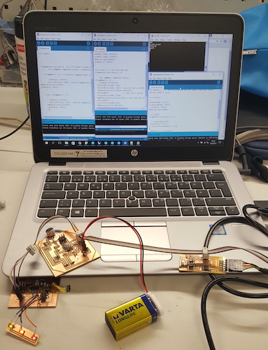
During this week I was refining coding, assembling the project and making the slide and the video presentations. Assembling the project was was not easy primarily because of the network wiring. I had to make a new connecting ribbon cable because I could not use the one I made during the networking week. I realized that that cable was not able to fit all of the boards because of the way I defined pins on them.
I started with fitting in the screen and the LEDs. Using connectors and ensulating tape, I made sure the are secure and they will not be short circuted.
After the screen and the lights were fitted in, I attached the boards to the box with the double-sided tape. It worked and the boards seems to be attached fine to the box. However, to ensure a more solid fit, I used hot glue to attach them to the box.
Final Presentation
Acknowledgements
Thanks to Neil Gershenfeld and everyone else involved in creating FABAcademy for coming up with this idea and developing it. I am sure it is an adeventure for many around the globe.
Thanks to the Faculty of Information Technologies and Electrical Engineering at the University of Oulu for providing means to participate in the course. Without FabAcademy, the semester would have been rather ordinary.
Thanks to the supervisor Harri Oinas-Kukkonen, and the Oulu Advanced Research on Service and Information Systems (OASIS) team for putting up with my constant involvement with the 'extracurricular project' which might have somewhat distracted my from my primary tasks :)
From where I started getting this far would not have been possible without help and support of the Fabulous peers and staff. Many thanks to Jari Pakarinen, Iván Sánchez Milara, Mikko Toivonen, Yrjö Louhisalmi, Eino Antikainen who went through the course with me and to Jani Ylioja, Juha-Pekka Mäkelä, Dorina Rajanen, Antti Mäntyniemi who guided us.
Thanks to Mother Nature giving us coffee and to plenty of sunlight in Finland in May: both helped keeping body and soul together during the last two weeks of project preparation.
Files:
Laser cut box original .svg design, .pdf used for cutting and .dxf designs, vinyl cut sticker .svg original design, .pdf used for cutting and .dxf designs, 3D printed support original Fusion .f3d and .stl design, mold original Fusion .f3d and .stl files, boards' files: .sch, .brd Eagle design files, .rml millig files, .ino Arduino code.