This would give enough movement so as to provide fluid movement with enough accuracy to create a simple text or graphic design. A basic diagram was established as a starting point.
A basic d
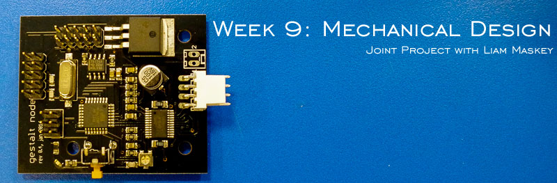
This week's assignment is a group assignment. The basic premise is to design a machine (mechanism+automation), including the end effector.
The stages are to:
1. Build the passive parts and operate it manually.
2. Document the group project and your individual contribution.
I will be completing the assignment with Liam Maskey.
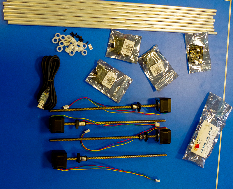
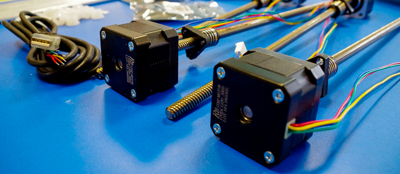
Given 4 stepper motors, and open access to an end effector of your own choice, the possibilities are bewildering. Just establishing exactly what you would like to build is a challenge in its own right. So a little judgment is needed, both in terms of finding something that will be interesting enough to build, but will also match the capabilities and size of the team.
We decided that something fun would be good, and in recognition of a well publicised human rights case here in Ireland in recent years, whereby someone was refused a cake by the vendor due to the nature of the message that they wanted printed thereon, it was decided that a cake decorating machine would be an interesting proposition.
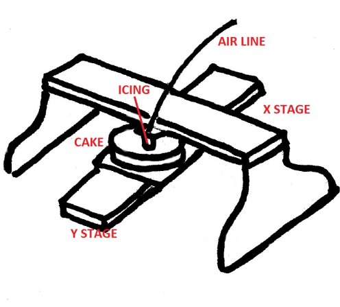
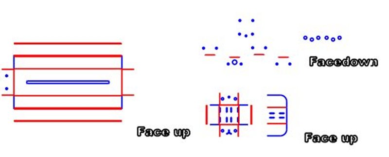
The basic concept for the machine was really quite simple. The icing would be contained within a syringe, which coule either the plunged via one of the stepper motors, of hydraulically via a pressurised system. The syringe would be mounted on a gantry, that could move from left to right via operation of stepper motor (x axis), and the cake itself could be transported forward and back on a ground stacked rail, driven by a second motor (y axis).
This would give enough movement so as to provide fluid movement with enough accuracy to create a simple text or graphic design. A basic diagram was established as a starting point.
A basic d
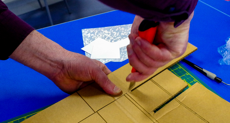
 During the research phase, Liam had identified a pre-existing file, comprised of folded cardboard which had the potential to act as the chasis for both axes.
Unitially we had a lot of issues with this file. It was downloaded as a .dxf, and on initial loading into Inkscape for preparation for laser cutting, the file was heavily corrupted. We then tried using FreeCad, LibreCad, Fusion360. All of which presented a few problems. Eventually, QCad seemed to open a true representation of the file. Subsequent to this, the file was saved as a .svg and opened within Inkscape.
Now the file could be prepared for Laser cutting, and sent to the Epilog Fusion for cutting.
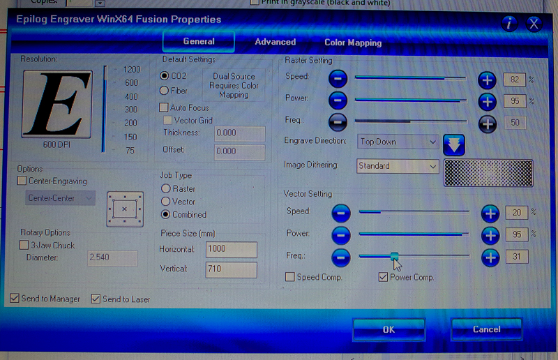
During this time, I prepared the files within Inkscape, cut them on the Laser Cutter whilst Liam assembled the cut parts.
 To be honest, Idid not really enjoy working with cardboard, and i have concerns over rigidity and future stability. So, after almost 1 full day of wrestling with the cardboard design, a decision was taken to abandon this, and adopt a strategy that involved drawing up a simple design from scratch that would be assembled from 3mm ply or mdf.
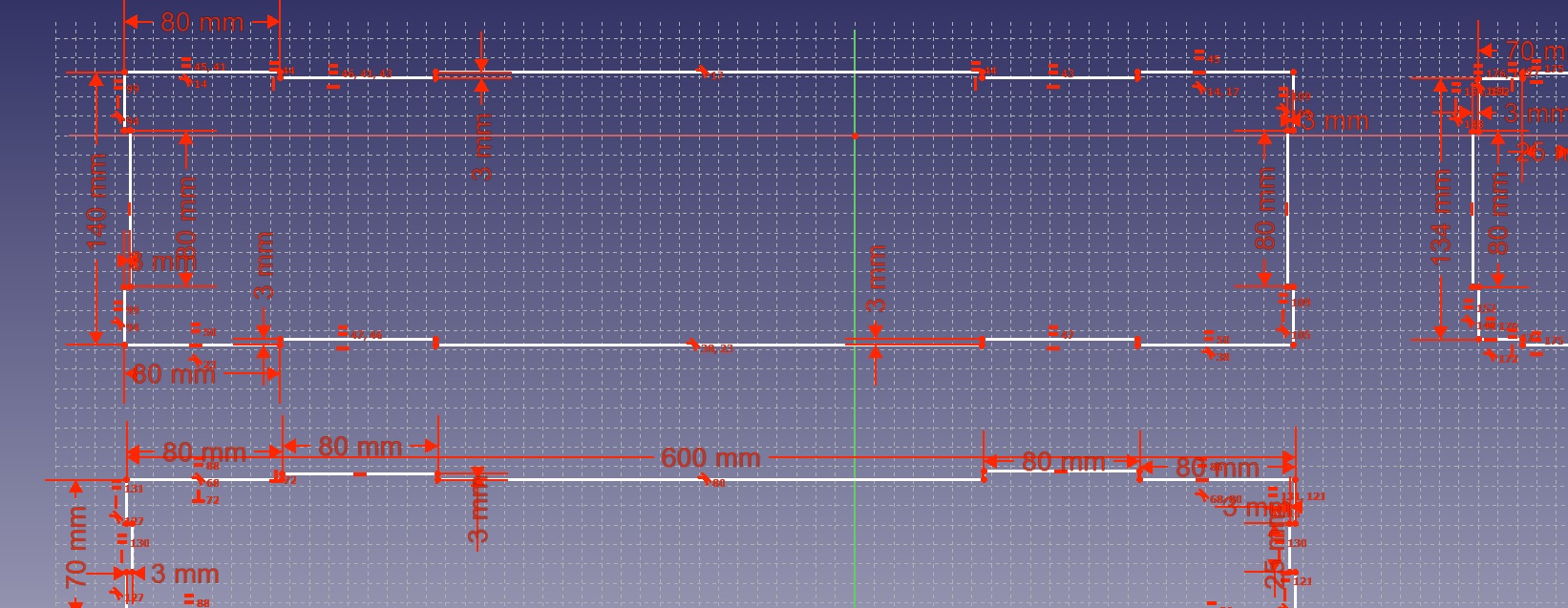
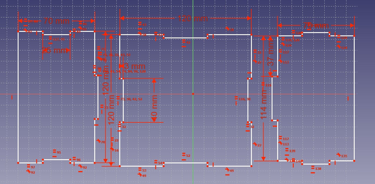
I created a file within FreeCad, and quickly drew out the components for an open on one side box. A few joints were included along the edges to give a more rigid structure. The design will be glued and clamped when cut.
The resultant file was loaded into Inkscape, and sent to the Fusion Laser cutter for cutting..
 The next step was to fabricate the base for both the cake and the syringe. These would form the basis for the moving parts of the machine.
A simple box structure was drawn in FreeCad, and sent for cutting. I used 4mm MDF, which is both freely available in most Labs, and also cheap.
The results are as follows:
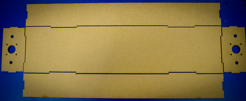
Once cut, the parts were assembled and glued / clamped until set.
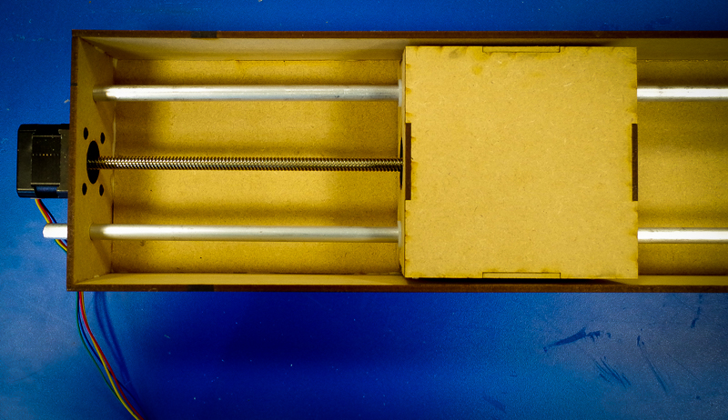
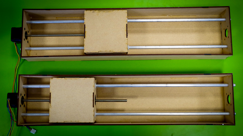
The design was very simple, with the stepper motors mounted outside the main box structure, with the smaller square box, that was to be the moving part running on the aluminuim rods.
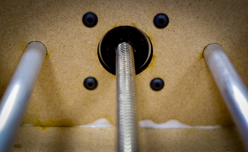
In order to ensure accurate mounting of the stepper motors, i carefully measured the distance between the threaded mounting holes, and fed the dimensional data into the FreeCad drawing. A hole was then cut to allow the raised centre section of the motor to fit through, giving a flush fit against the mdf frame.
Two identical stages were constructed to form the x and y axis for the cake icing machine.
The next step was to test the hydraulic line that would drive the syringe as it pushed out the icing.
The compressor from the laser cutter was connected to a flow control device, and then through to the syringe, We played about with the pressure until we got a smooth flow on the ram inside the syringe.