
This weeks assignment has a few facets, all of which can be realised on the vinyl cutter and laser cutter. The required steps were to
1. Design and make laser cutter test parts so as to evaluate kerf, and to establish cut settings for accurate press fit assemblies
2. Cut something on the vinyl cutter.
3. Design and cut a press fit kit of parts that can be assembled in various forms, utilising parametric control to allow for variance in kerf and sheet material variance from stated thickness.
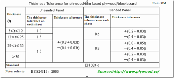
The majority of sheet materials have a specified tolerance. Kerf can also vary in relation to speed/power settings with each material, and also the current state of the optics. This variance, in a press fit construction, means that we cannot rely on the specified thickness as a guide for slots. There are however strategies to counter this. Firstly, we can test for kerf, and also we can also perform a slot test on our specified material. The results of these tests can then be fed into our parametric design so as to ensure optimum fit on our assemblies.
In order to establish kerf, i drew a simple 30mm square in inkscape. This design was then sent to one of our laser cutters. The resulting cut was measured both in terms of the width of the cut square, and the resultant hole in the sheet material. The measurement difference was divided by 2 to give the kerf.
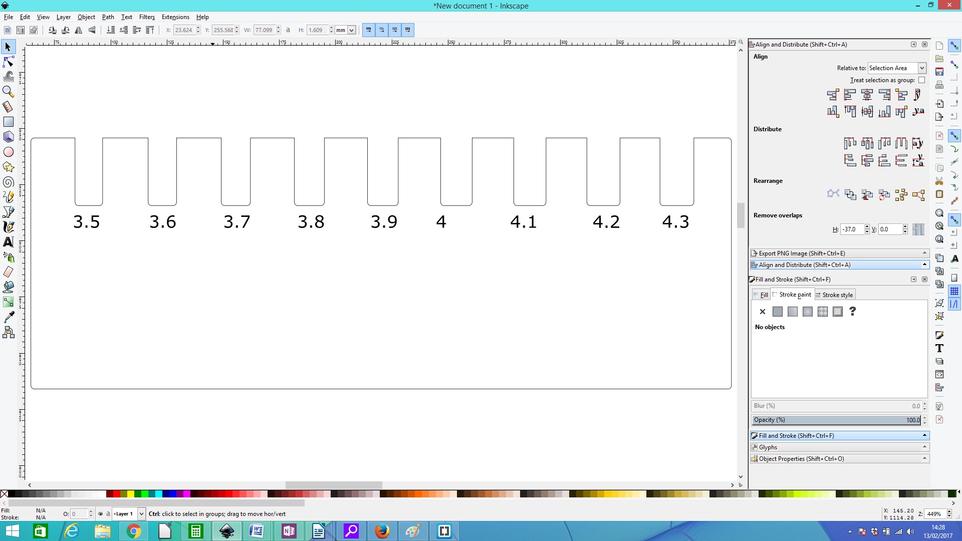
In order to ascertain the best slot size for a given material, a simple slot test can be run. This involves the creation of 2 identical parts containing a range of slots with widths that modulate around the stated material thickness. So, for this test, as I was utilising 3mm ply stock for my assembly, i selected slots ranging from 2.6 to 3.4mm. The 2 parts are then engaged at the different slots until you find the thickness that represents the best fit.
Design
Essentially a 2d medium, effective design for vinyl cutting can be achieved on any vector based software package. Inkscape was my package of choice due to its versatility, speed of use and clear, uncomplicated interface. to be honest I was a bit disappointed at the exclusion of Inkscape from this weeks assignment, so i decided to make a t-shirt to show my support of this design package.
Like all other cnc machines within FabLab, the vinyl cutter requires vector based objects. There are 2 main options for the creation of vectors
1. Drawing from scratch
2. Extracting vectors from bitmaps
I decided to opt for option 2.
For the purposes of this assingment I decided to design and make a t-shirt design, and vinyl decals for my laptop.
T-Shirt design
In support of Inkscape, i thought it would be a good idea to make a t-shirt design expressing the message "draw freely."
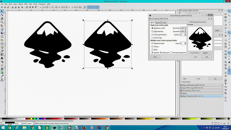
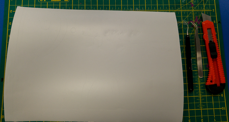
First off, I copied and pasted a bitmap of the Inkscape logo from google images into a new page within inkscape.
Then, using the "trace bitmap" option, i extracted vectors from this. The vector im age can then be moved to one side, and the original bitmap deleted.

The resultant vector can then simply be copied and pasted into Cut Studio, where it can be resized accordingly. Also, adding text is simpler if done directly within Cut Studio due to the fact that true type fonts will instantaneously creeate vectors within the design.
I added "Draw Freely", and also "Fab Academy 2017".
In order to make it a little easier to weed, a rectangulare box is drawn around the design.
Important: due to the nature of the garment transfer vinyl, it is essential that you mirror the design before going any further. Failure to do so will result in a complete failure of the assignment.
The design is now complete.
Cutting
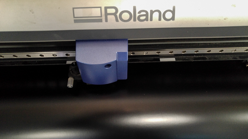
Now that the design is complete, it is time to start cutting. The garment vinyl is fed into the GX-24, and roll is selected as the type of media. The cut head is then sent to the bottom left corner, and this is set as the origin. The machine is now ready to accept a file for cutting. Appropriate speed and force settings for the media in use can be selected now, and it is also a good time to check how far the cutter is protruding from the holder. A handy test here is to remove the cutter from the machine, and set the blade to be just protruding from the base. Now manually see if the blade will cut through the vinyl. If it does not cut clean through, expose more of the blade, if it cuts through the backing substrate, retract the knife a little into the holder.
Now simply chose the cutting option from the drop down menu and select ok. The vinyl cutter will now follow the vectors, cutting your design.
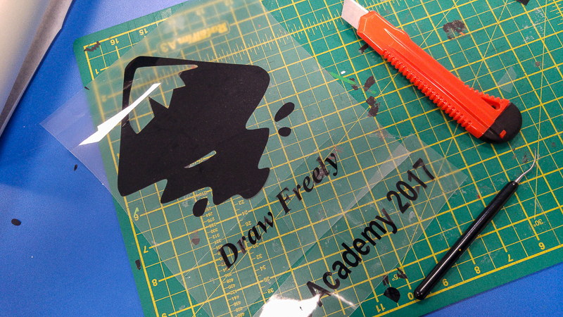
Weeding
The vinyl cutter does not remove the unwanted parts of vinyl from the meduim. This has to be done manually. The process is referred to as "weeding." Tweezers or a weeding tool are used to pick the vinyl from the backing, and the rest can be removed by hand. It is preferable to keep the material being removed as close to horizontal plane as possible in order to avoid the edges of the wanted design lifting off as you weed.
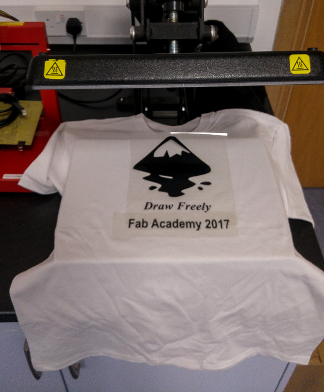
Heat Transfer
Now that weeding is finished, it is simply a matter of placing the t-shirt on the bed of the heat press, with the cut vinyl on top. The heat press it then closed for 15 seconds at 160 degrees so as to activate the adhesive.
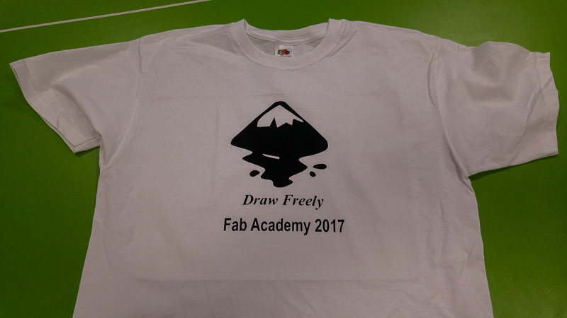
Once the time is up, you simply remove the backing and you are left with the finished t-shirt.
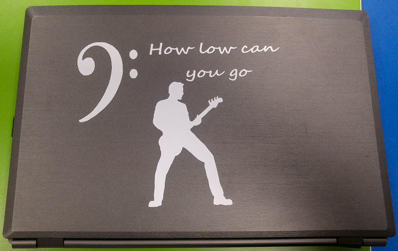
As an extra project, I decided to make some decals for the top of my laptop. As a long term bass player, I decided it would be good to have something to reference this.
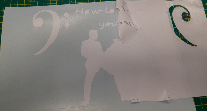
I followed the same procedure as before, only this time after weeding I had to urilise transfer tape to lift the completed design off the backing and onto the computer. The results can be seen below.
Problem: I work in the premier creative arts centre in the north of Ireland. There are many facets to this organisation, one of which is the performance space. The bar area in this space has just recently been renovated and extended to provide a small stage space for performers. Whilst the new area looks fine, the stage is a little too reverberant for comfortable foldback monitoring during louder performances. Although this is a small space, we may need to provide 4 or 5 disrete mixes back to the performers on stage, and the current ambience makes it hard to retain separation for the individual performers.
Solution: Design and install an acoustic panel absorber array above the performance space.
There are many types of acoustic treatment available commercially. These are expensive. Having a FabLab in the centre provides a perfect opportunity to extend the concept of digital personal fabrication into the very fabric of the building. The design will be very simple. A 3x3 array of 300mm square panels, cut from MDF, that will have rockwool RW3 as an absorbtive medium on the rear. The panels will have slots cut on the front. This will allow for both absorbtion and diffusion. The panels will be arranged in different heights, increasing the sense of the third dimension in the design. If the panels are successful, I will adapt the design for application on the walls of the same space. Once assempled, the panels will form a desinn like this:
The principal focus of this weeks assignment is the use of parametric control within software to enable precise press-fit construction techniques when using a laser cutter. I have used Inkscape before, and find the inbterface very intuitive, but the lack of true parameterised control rules this out. So, following on in the spirit of open source, i decided to give FreeCad a try.
To be honest up front, FreeCad is not anywhere as intuitive to use as a package like Inkscape, Corel Draw or Illustrator. the initial stages of the design take a little time to get established. The inclusion of constraints in some of the objects also leads to problems, and for this, i ended up mainly using polylines for the basis of the shapes.
However, the ability to strictly control slot widths and spacings is a very handy feature.
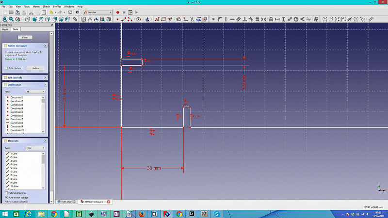
The first part of the design was getting the dimensions for the panel front correct. I decided on 295mm square as this leaves a little tolerance when cutting from the standard 600x300mm sheet. The slots for the joiners were set to be 30mm from each edge with a depth of 10mm. The initial width was set at 3mm, but this was adjusted to 3.2 after the slot test. having direct control of each slot width through adjustment of only 1 parameter made changing of the design to suit the stock very simple and quick.
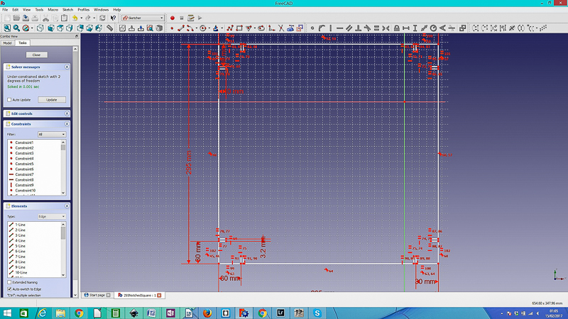
Next up was to create a small retainer for the acoustic material set to go on the rear of the part. Another square was drawn with similar dimensions, but this one was to only be a 20mm wide band that would go around the outside of the square. The files were saves as both freecad files and as .svg for transfer into Inkscape for further treatment and preparation for cutting.
With the main panel part complete, all that remained was to design the parts that would both hold both parts of the panel together, and also join the panels in an array. A simple rectangular part with notches was drawn up, again in FreeCad.
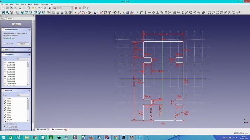
Three different lengths of joiner were designed, at 100mm, 200mmand 250mm. The idea being to be able to adjust the relative depth of each panel.
Once the main parts were completed, I saved the files in the .svg format and opened them within Inkscape. I am familiar with the workflow from Inkscape to Laser cutter, and also there were some remaining design steps needed that I felt would be easier achieved in this software.
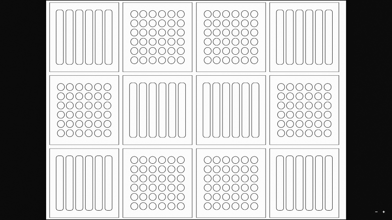
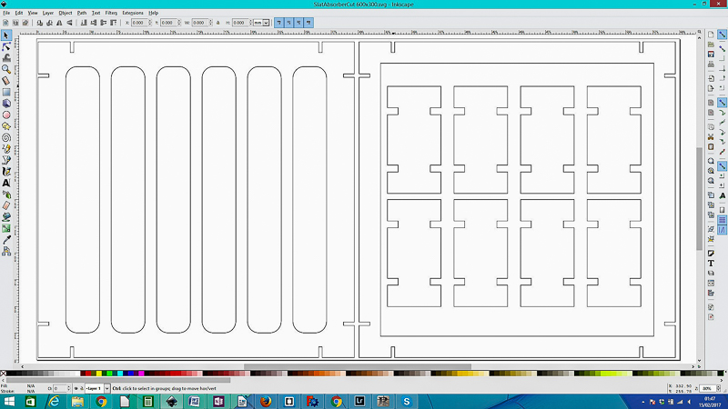
Slats and holes were incorporated into the design, and a document representing the bed size of the laser cutter was opened and populated with the design.
In order to save stock, some of the joiners were nested inside the design as appropriate. An example cut file can be seen below;
Now the stroke of the vectors can be set for operation of the laser. With Epilog lasers we need to set the stroke to .01mm, black with 100% opacity. Failure to establish these settings will lead to failure. Now it is just a matter of setting the spped and power parameters on the laser cutter, setting home, and then cut. It is essential at all times to use both air assist curtain and extraction when running the laser. Also, in case of fire, the machine nhas to be manned at all times when operational.
,