Input Devices
This week's assignment stated;
"Measure something: add a sensor to a microcontroller board that you have designed and read it"
I worked with an ultrasonic sensor as my input device.
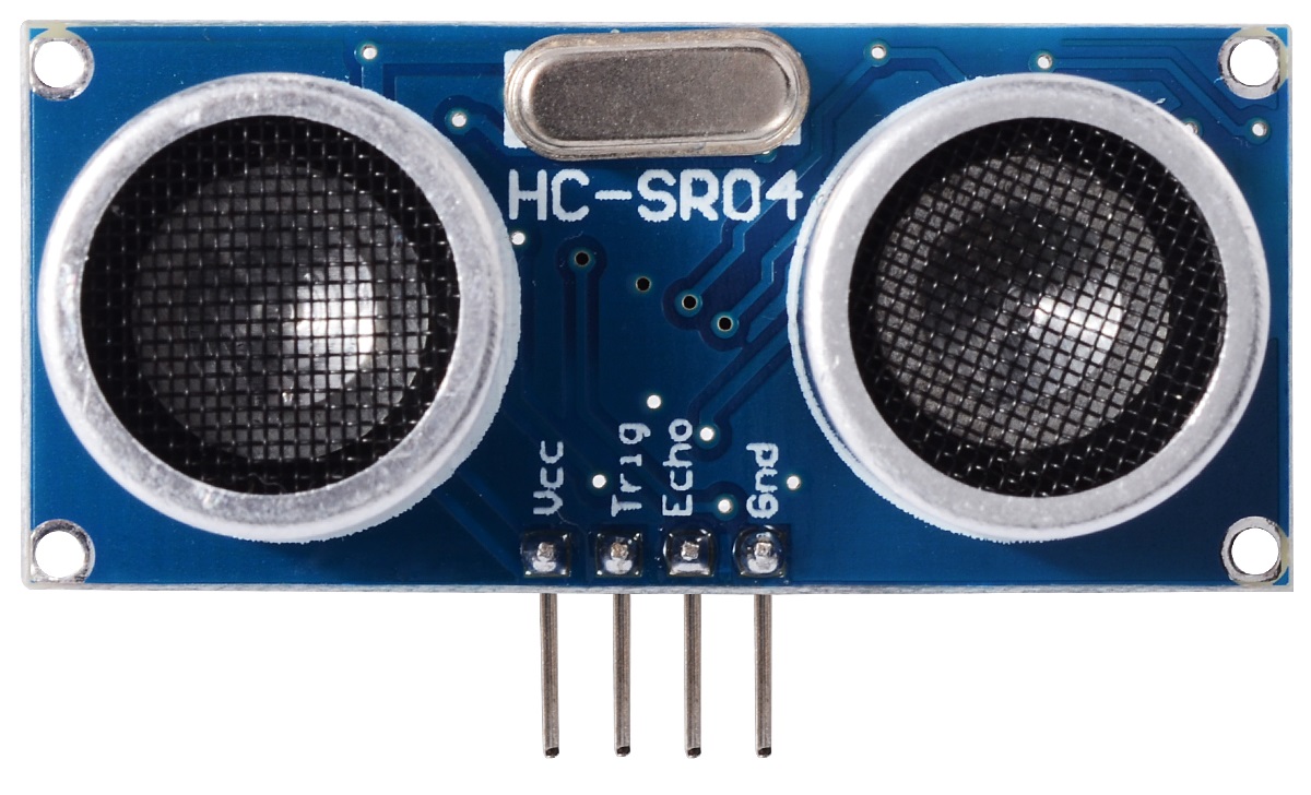
An ultrasonic sensor is a device that measures distance by sending out a sound wave at a specific frequency and listening for that sound wave to bounce back. The sensor includes an ultrasonic transmitter, a receiver and a control circuit. By recording the elapsed time between the sound wave being generated and the sound wave bouncing back, it is possible to calculate the distance between the sonar sensor and the object.
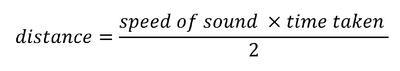
The product of Speed of sound by the time taken is divided by 2 because of the round-trip distance. Round trip means that the sound wave traveled twices the distance to the object before it was detected by the sensor; it includes the trip from the sonar sensor to the object and the trip from the object to the Ultrasonic sensor receiver.
The sensor has four pins only. VCC (Power), Trig (Trigger), Echo (Receive), and GND (Ground)
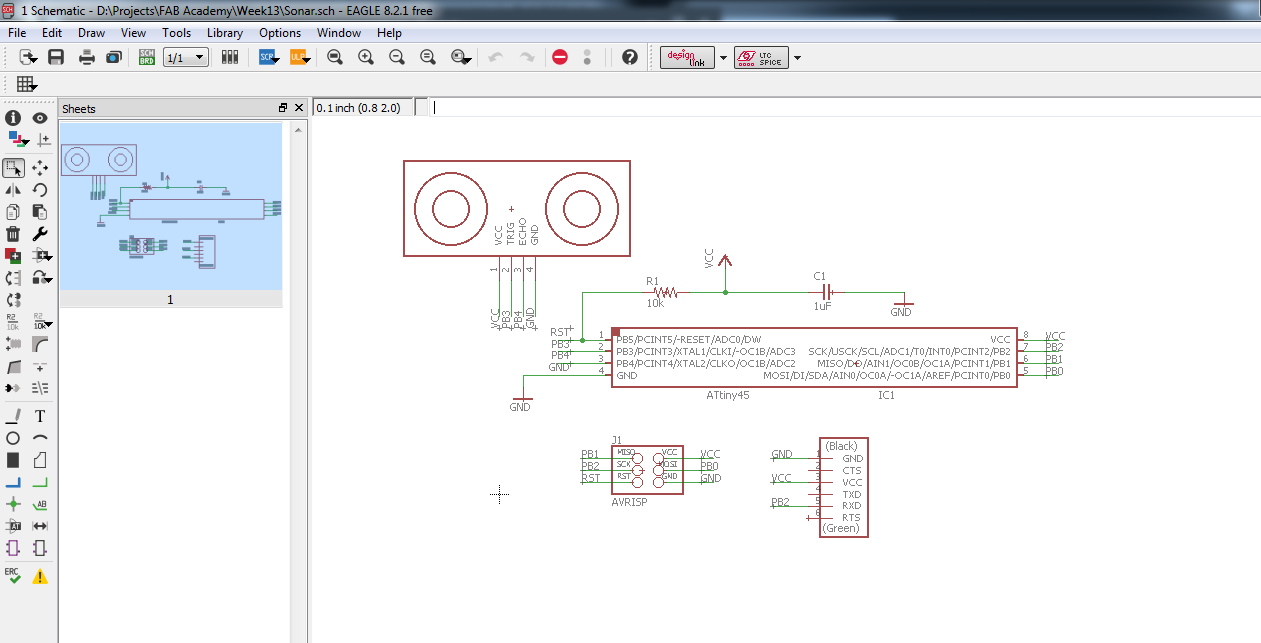
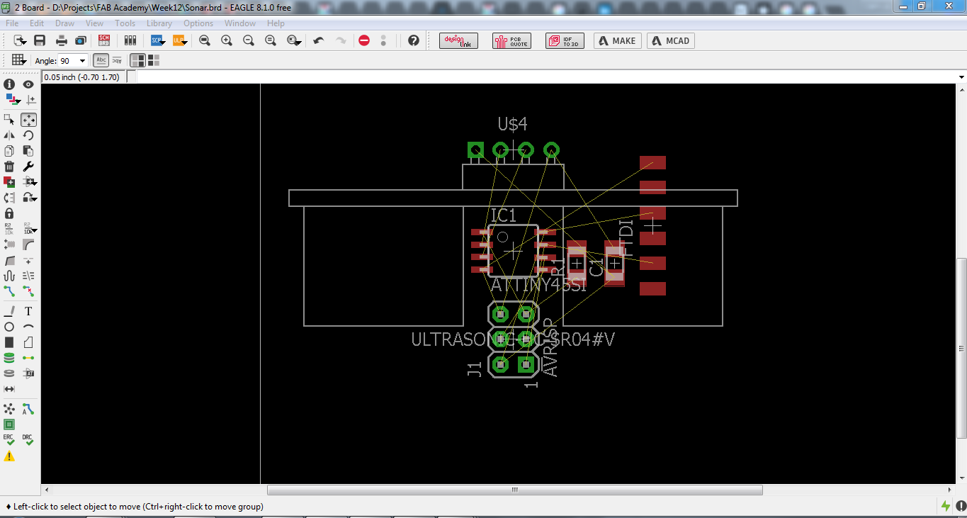
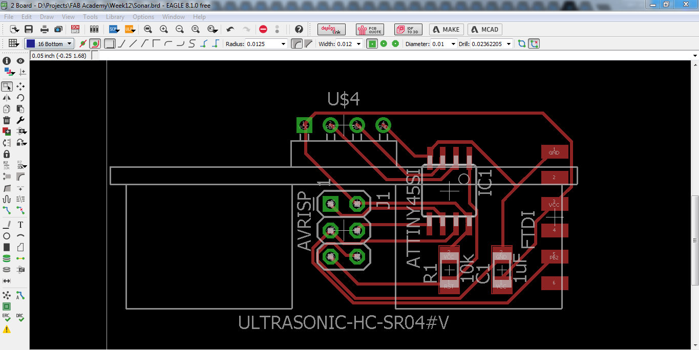
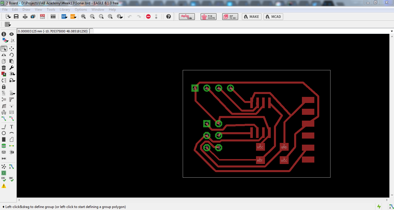
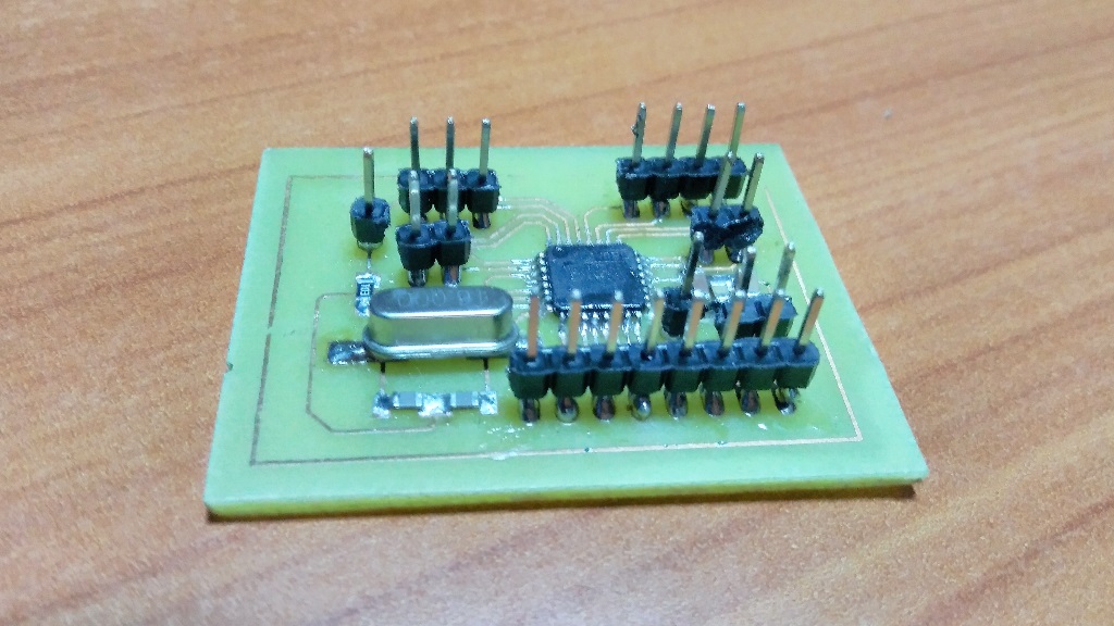
I started by designing the circuit board on eagle.Since we only had through-hole headers in the lab, I designed in anticipation for that.So I selected through-hole header packages from the components library. After placing all the necessary components I arranged and connected them together. The circuit was going to use an Attiny45 microcontroller
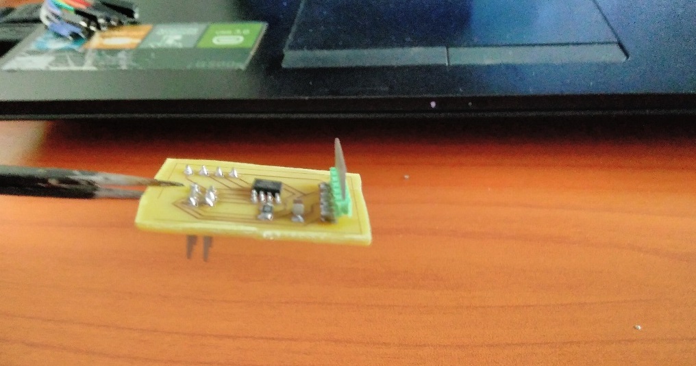
The last of 1/64" milling bit had broken so I went on to etch the board using hydrochloric acid (HCL)
I then drilled through the board for the through -hole components and soldered the components on the board
Programming
I downloaded the c code and make file here.
I was using an attiny25, so I editted the make file to read attiny25 and not attiny45.
Then I connected the board to FTDI and to the usbtiny ready for programming.
I ran the make file
sudo make -f hello.HC-SR04.make
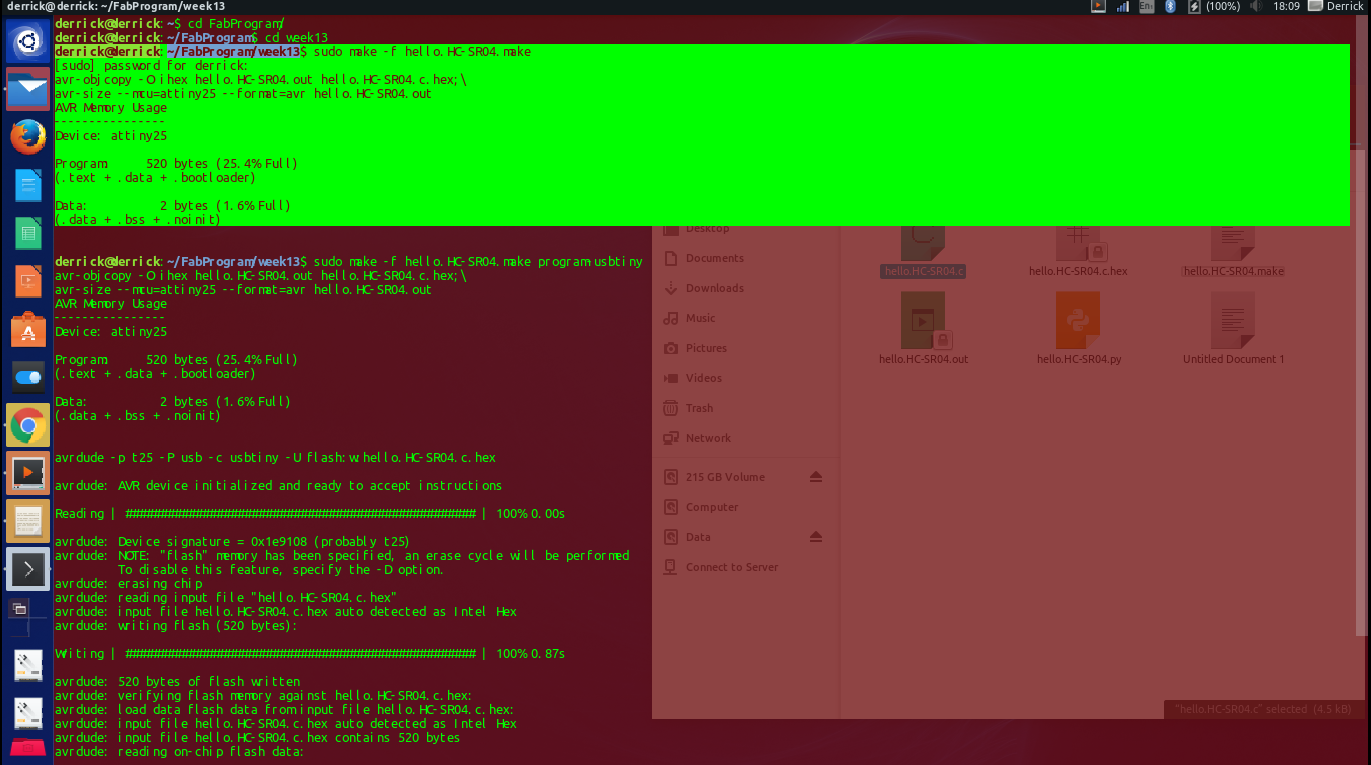
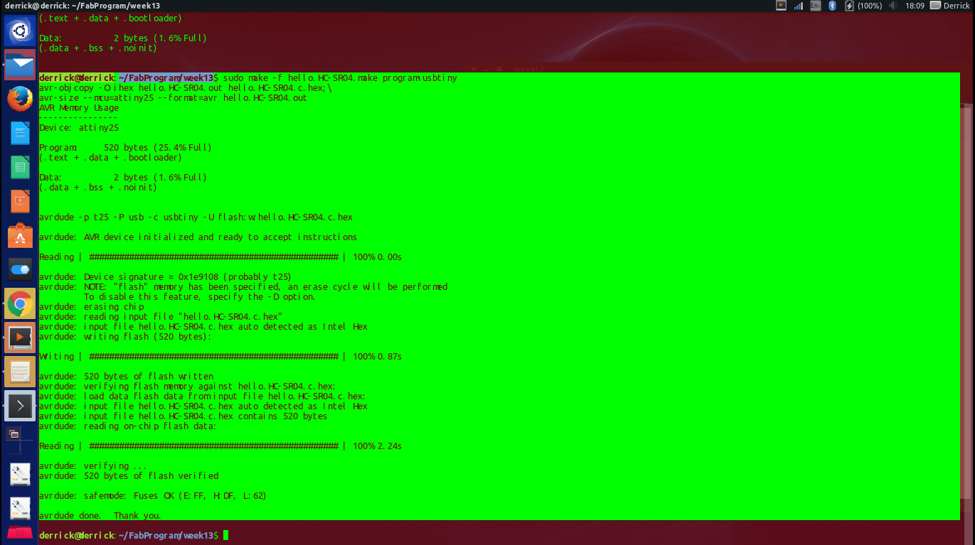
I finally programmed the chip 'sudo make -f hello.HC-SR04.make program-usbtiny'
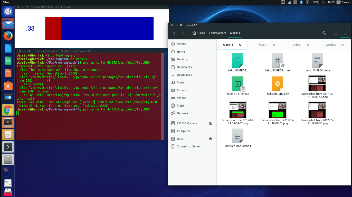
After this I ran Neil's python program in order to view the sensor's feedback on the desktop. I however got some errors while doing this
By the time I get to troubleshoot my board further, I did not have an FTDI cable anymore. So I had to seek other means of utilising the sonar sensor.
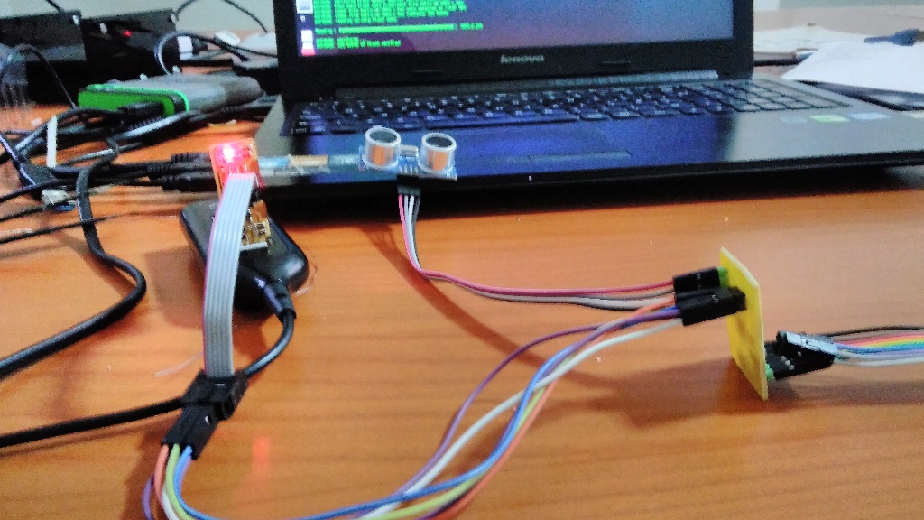
I did some reseach and learnt that I could use the arduino board as an FTDI cable for serial communication. Basically I will only need it to receive the data my device is transmitting and dispay it on the screen for me to read.
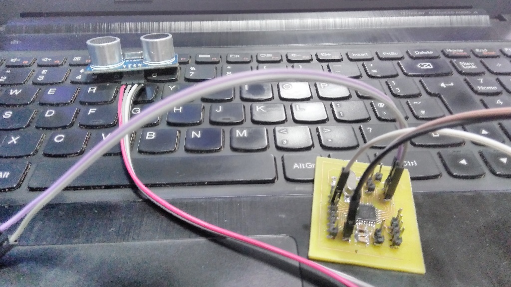
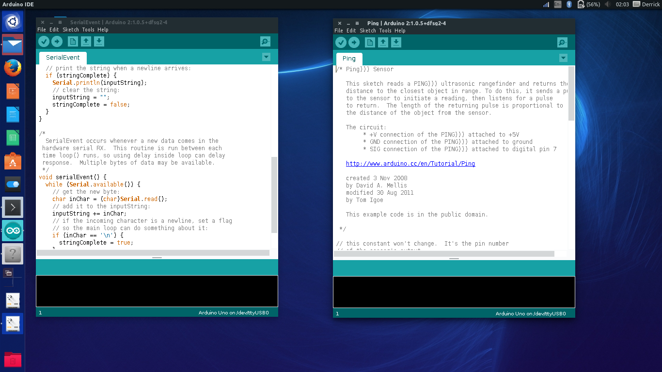
Earlier on I had designed a satshakit as part of my preparation for the final project. Its documentation will be found on my final project page as planned. I took the satshakit micro board and uploaded the code'ping' from arduino IDE to it and uploaded the code 'serialEvent@ to an arduino board. I then connected the board with SerialEvent to the computer and the satshakit pin 1 to the pin 0 of the arduino board. Pin 1 of the satshakit is a transmitter and pin 0 of the arduino is a receiver, so that right there was all I needed :)
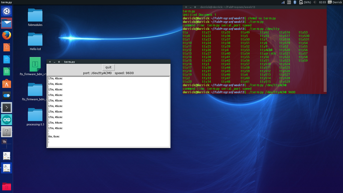
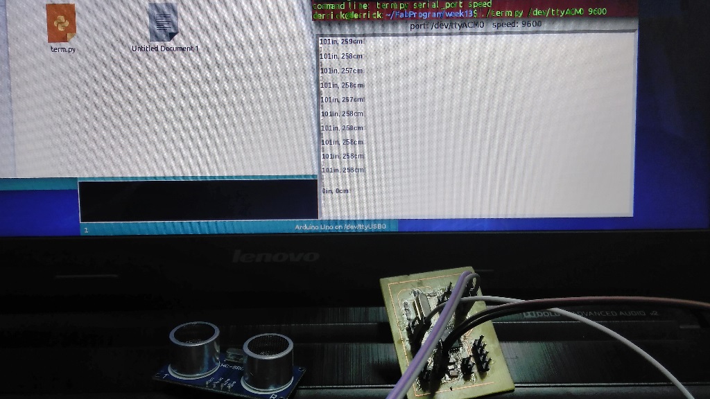
I then downloaded term.py from communication and ran it through terminal. This is what I observed
Download files:
Sonar.sch
Sonar.brd
hello.HC-SR04.c
hello.HC-SR04.make