*EIGHTH*WEEK: Embedded Programming
Assignment
1. Individual assignment:
- Documented what you learned from reading a microcontroller datasheet.
- What questions do you have? what would you like to learn more about?.
- Programmed your board.
- Described the programming process you used.
- Incluided your code.
Individual assignment
ATTINY 44 DATA SHEET:
Below I will describe the most important parts of the datasheet of Attiny 44 microcontroler.
1. Pin configurations
 This image show the pin configuration of Attiny 44 with the number of pins that we use in arduino, but some pins can have more configuration, such as:
PB0: CLKI
PB3: dW
PB2: CKOUT
PA3: T0
PA4: T1
PA5: DO
PA6: DI
PA7: ICP
The pins we can divide these into different parts:
1. VCC: supply voltage
2. GND
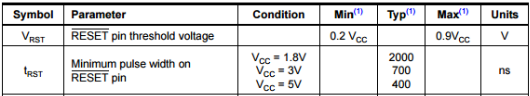
3. PORTB and RESET: It has 4 pins (PB0-PB3) and these are characterized by being a 4 bit bidirectional in/out port with pull-up resistors. PB3 has the RESET capability, A low level on this pin for longer than necessary activates the reset. You have to considere the minimum pulse length and the clock to do a reset.
 4. PORTA: It has 8 pins (PB0-PB7) and these are characterized by being a 8 bit bidirectional in/out port with pull-up resistors. The port A pins are tri-state when RESET becomes active. You can see in pin configurations image that the port A has the functions of ADC (analog digital converter).
2. Memories
registers
SRAM
EEPROM
FLASH
3. Peripheral features
- RegistersOne 8-bit and One 16-bit Timer/Counter with Two PWM (pulse-width modulation)Channels, Each
- 10-bit ADC
- Programmable Watchdog Timer with Separate On-chip Oscillator
- On-chip Analog Comparator
- Universal Serial Interface
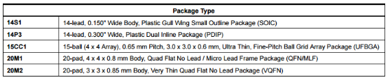
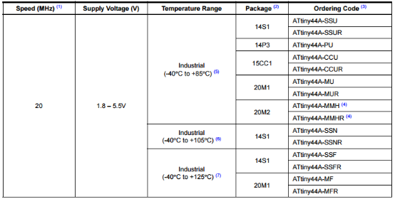
4. Packages
The expecific packages of attyni44.
 5. clocks
Attyni44 has different clocks, for example:
1. internal 8 MHz oscillator
2. internal 128 kHz oscillator
3. Crystal oscillator / ceramic resonator.
Also Attyni44 has a clock subsistems such as:
- CPU Clock
- I/O Clock
- Flash clock
- ADC clock
This datasheet I used in previous weeks, in less depth to understand mainly what were their pins and what were their port input and output.
- In exercise03 to Know the pins.
- In exercise05 to Know the inputs and outputs ports.
- And others datasheets in exercise09
- And others datasheets in exercise12
PROGRAM MY BOARD: I had to learn with differents tutorials and read the references about parts of the arduino programming. I did tutorial about how to turn on a led and use a button to change the status of the led. I used the oficial web to read the reference.
https://www.arduino.cc/en/Reference/HomePage
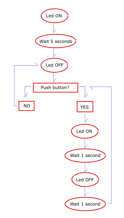
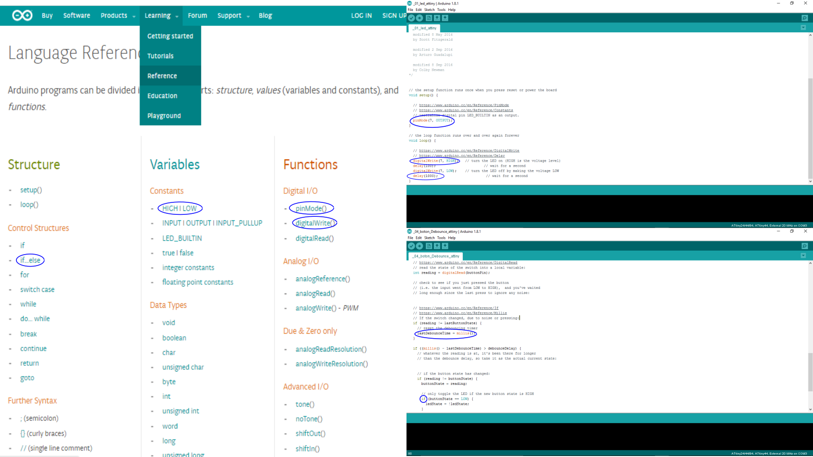 After I did the tutorials, I designed a schematic about void loop of my board.
 To write my arduino programming I needed to Know several concepts, such as:
1 . Variables: is a place to store a piece of data. First I have to declare the variable, before "void setup" to encompass all programming. The parts of variable are: the type ( int, long, unsigned long ....), the name that has to be different from the arduino predefined expressions (pin, buttonState ...) and a value that doesn't have to be defined in the declared variable (a constants or a number).
My variables were copied from other examples and I used "unsigned long" for the value of time.
2 . Void setup: Here you define the pins and its status. You can use "pinMode" function, where you put between parentheses the pin (in number or in variable) and the state (INPUT, OUTPUT or INPUT_PULLUP).
I had to change the constants in "void loop" because when you use the internal PULL-UP resistor does when the input is HIGH, the onboard LED attached to pin will turn on; when LOW, the LED will turn off.
3 . Void loop: Here the board operation is defined and looped. I used control structures like if...else, operator like = (assignment and not equal), == (equal to)..., function like: delay to stop the program in milliseconds but this has problem with sensors readings (like a button), also I used millis() to calculate the time since the programe start to run.
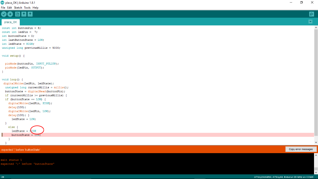
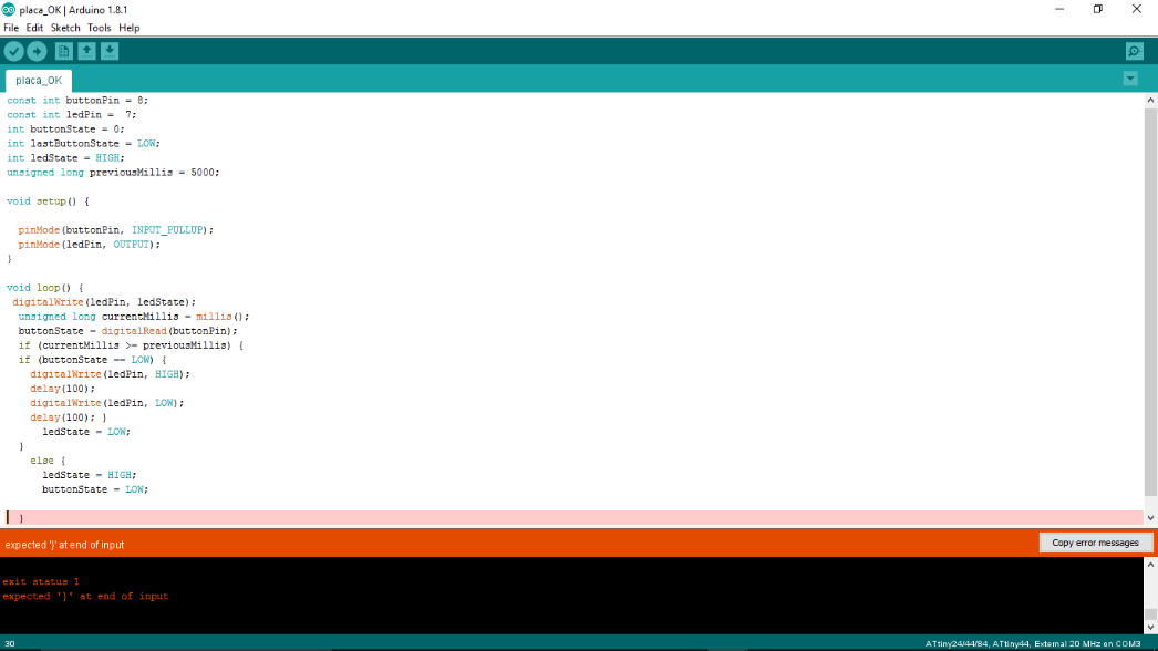
Finally I had a littel problem with ; becuse I didn't know that all variables and functions have to have a semicolon at the end.
 First I wrote the part of the state of Led, and second I added the botton.
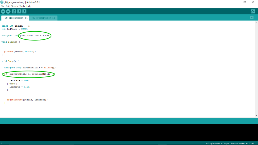
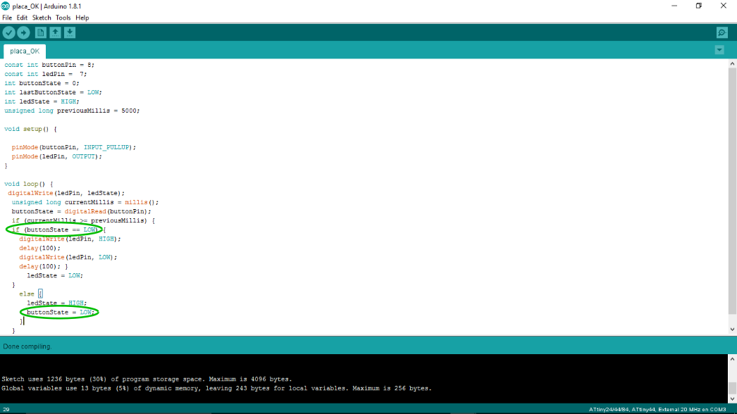
  const int buttonPin = 8;
const int ledPin =  7;
int buttonState = 0;
int lastButtonState = LOW;
int ledState = HIGH;
unsigned long previousMillis = 5000;

void setup() {

  pinMode(buttonPin, INPUT_PULLUP);
  pinMode(ledPin, OUTPUT);
}

void loop() {

  unsigned long currentMillis = millis();
  buttonState = digitalRead(buttonPin);
  if (currentMillis >= previousMillis) {
  if (buttonState == LOW) {
    digitalWrite(ledPin, HIGH);
    delay(100);
    digitalWrite(ledPin, LOW);
    delay(100); }
      ledState = LOW;

  }
    else {
      ledState = HIGH;
      buttonState = LOW;
    }

    digitalWrite(ledPin, ledState);
  }
The part that I found very interesting and perhaps more complex is that of memories. It gives me the feeling of not understanding this concept well but I would like to get to understand how to store information in a pin and then get it back after a while. Where do I store those bytes of information? How do I retrieve that information from a particular byte?
FILES:
- Code