Fabacademy 2017
Third Week
Index
Third lesson
Computer-Controlled Cutting
Following last week format we went through a wide range of software tools and techniques. First fabrication tools were introduced, the vinyl cutter –which we don't have yet at our fab lab and based on Neil high praises about it, it's now first in our priority list– and the laser cutter, we have some experience with this tool as we build a lasersaur ourselves four years ago.
Lasersaur (open source laser cutter) assembly time-lapse. Fab Lab Limerick.
Fablight was a great finding as I thought that similar technologies were much more expensive. Automated metal-cutting (and welding) is something we have been really interested about since we started our Fab Lab as digitally fabricated architecture is one of our main areas of research.
Third assignment A
Parametric press-fit construction kit
Last week I started using Freecad for the second exercise. To be honest, I am still finding Freecad's UI a bit buggy and not very intuitive so this week I planned to try out some other parametric tools such as Solidworks and Inventor.
Fusion360
I primarily work on a Mac so I installed both of them on a virtual machine but after doing some research it felt to me that Fusion360 –a freemium, cloud based, multi platform and fabrication oriented parametric software from Autodesk– may be a great way to get started in parametric modeling.
| Inventor | Fusion 360 | |
|---|---|---|
| General | Large feature set that requires some training, more expensive | Easy to learn, less expensive |
| Industry Focus | Aimed at large assemblies | Aimed at smaller assemblies (less than 1000-2000 parts, for example) |
| Modeling | Robust parametric tools | Freeform models |
| Add-ins | Numerous add-ins, including sheet metal, injection molds, chains, frame design | Not available |
| Work Environment | Local or network-based files | Cloud-based files |
| Usage Example | Designing complex assemblies such as conveyor lines or plant layouts | Designing less complex products that require both mechanical and freeform shapes, such as a vacuum cleaner or a leaf blower |
| Computer | Runs natively on Windows | Runs natively on both Windows and Mac |
| For More Information | Inventor product page | Fusion 360 features page |
I started with a simple tutorial in Hackaday for building a parametric box.
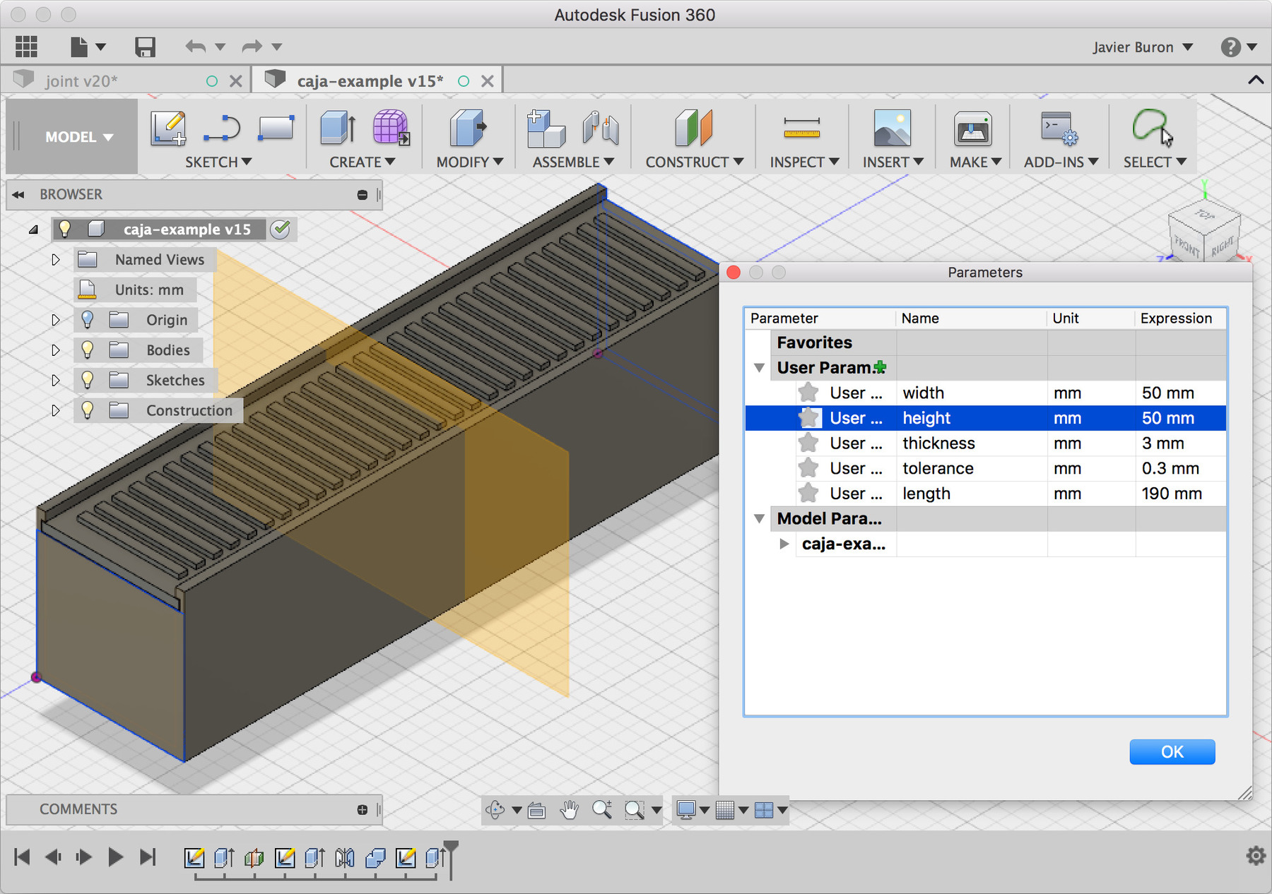
Sketches, constraints and variables are concepts used in most parametric design tools. As it was explained in the second class, using some sort of parametric design tool is a real necessity when working with digital fabrication tools. A parametric model allows the almost inevitable adjustments when fabrication happens, tolerance, kerf and real material thickness should be parameters in every design.
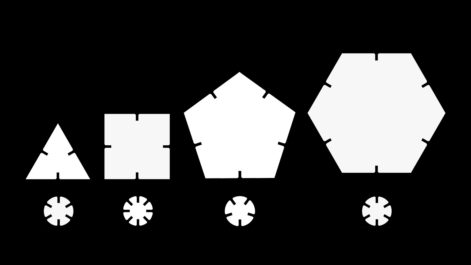
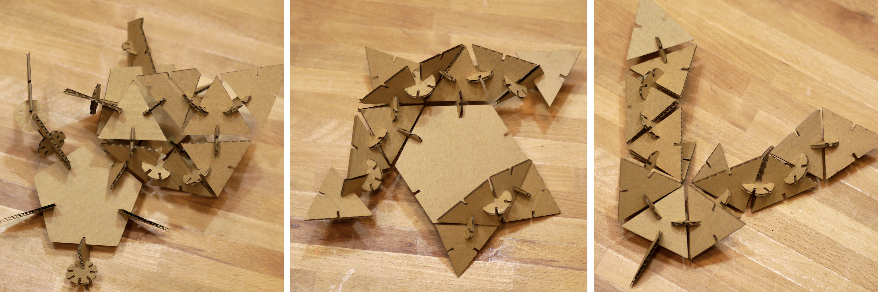
The press-fit design that I have been working on is quite simple and follows the same principles than GIK showed in class. Different angles are constructed by using pieces based on regular polygons with the same press fit joint so a triangle will allow 120º angles, a square 90º, a pentagon 72º and so on.
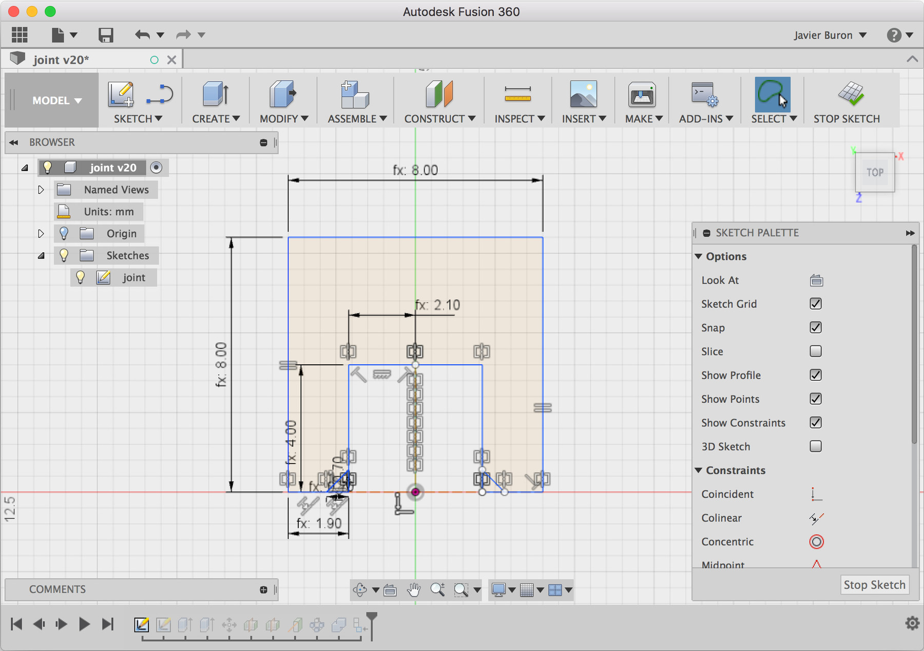
Instead of building each piece individually, I wanted to build a single parametric model that will produce all these variations. After a bit back and forth with the interface I managed to build a four side parametric piece that will constrain and resolve as planned.
I have to say that I was somewhat disappointed with the constrains feature to date. Building an intuitive GUI for these type of operations seems a quite difficult challenge in any case. I have plenty of experience with non-parametric design tools so this may be working against my learning process too.
Antimony
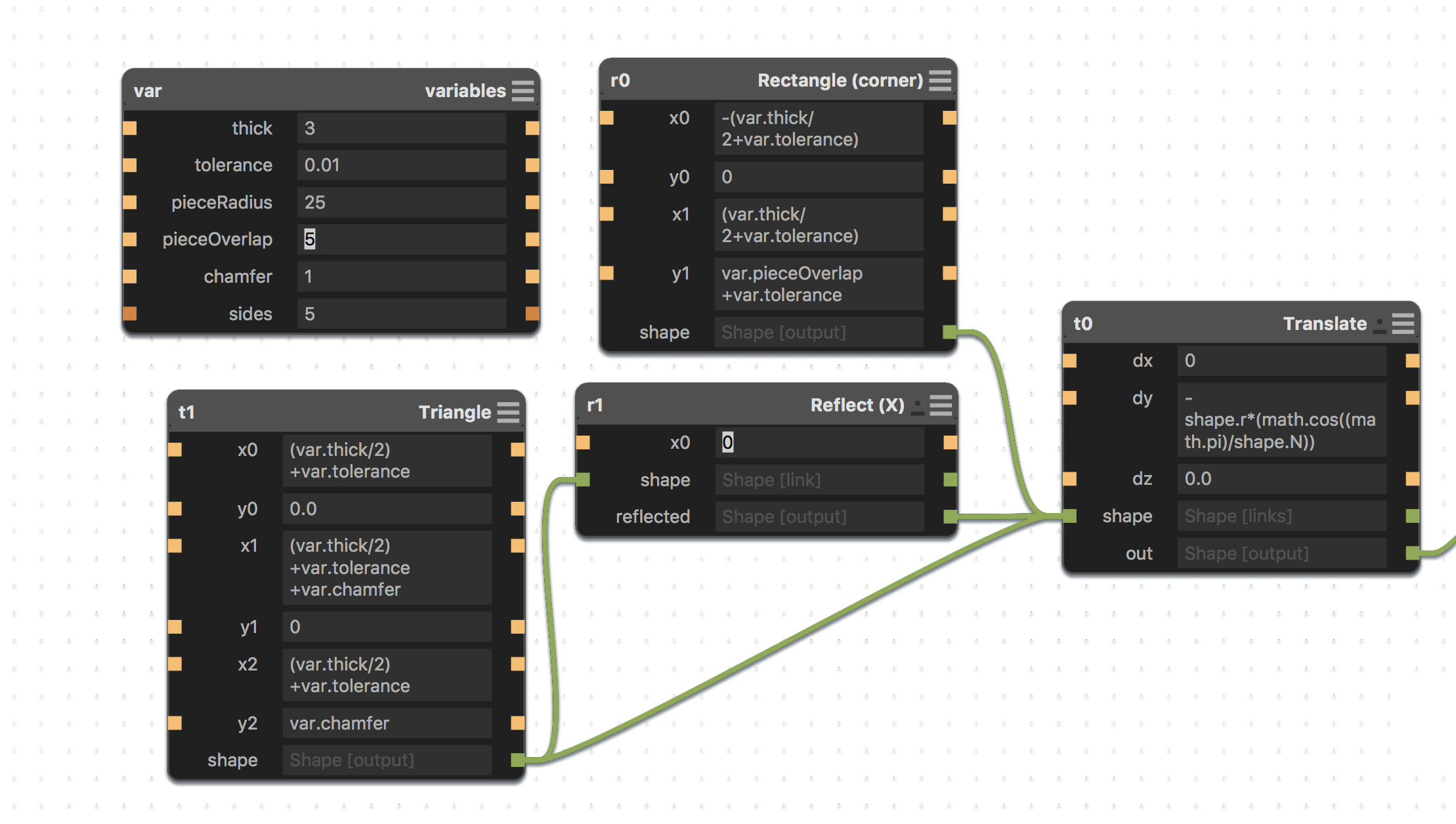
I realized that the proposed design could be defined mathematically quite simply with some basic trigonometry so I decided to give a try to Antimony.
So far I found it quite enjoyable, GUI is minimal and syntax is quite similar to other programming languages so calling out variables and parameters feels very intuitive.
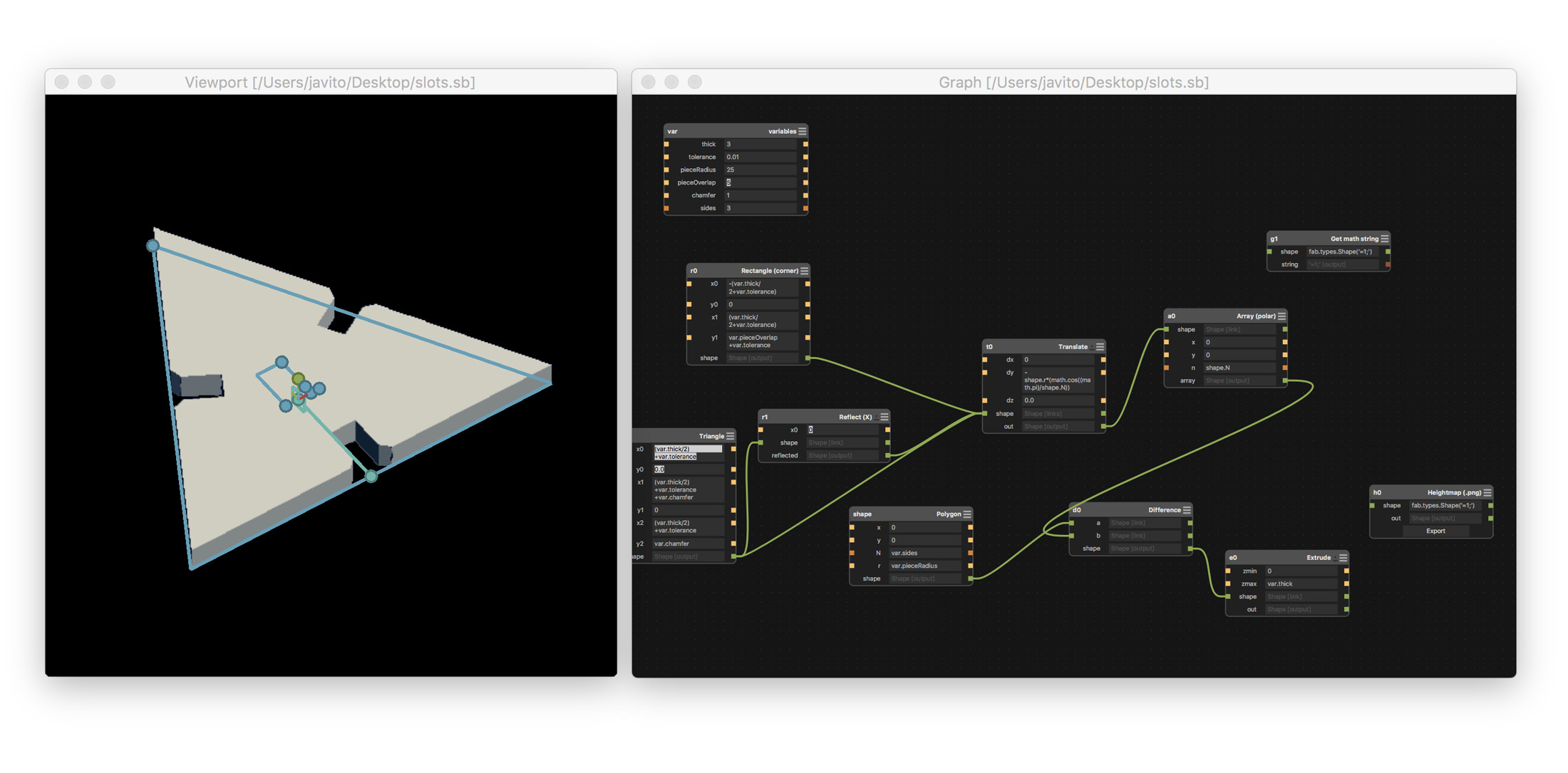
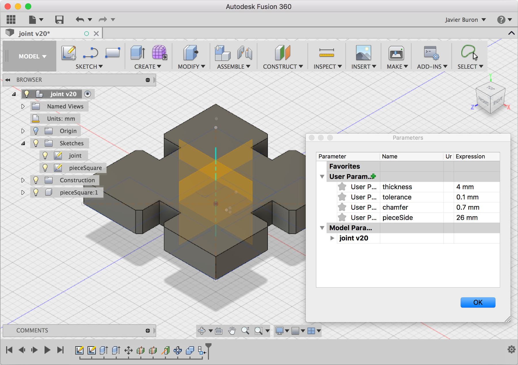
The current version uses the simplest joint that it was explained last week. I implemented a chamfer edge which can be adjusted easily in real units.
Sadly, I have a limited access to the laser and vinyl cutter this week as I have travelled from Córdoba to attend the Academy. I will be cutting the pieces this evening, hopefully it will work out!
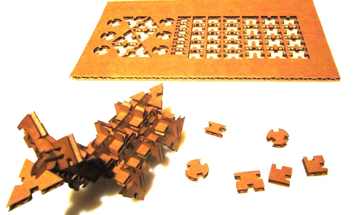
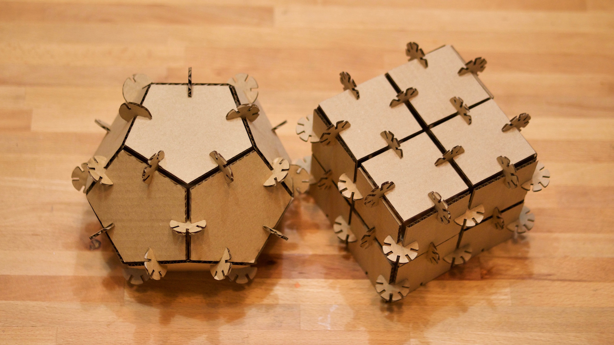
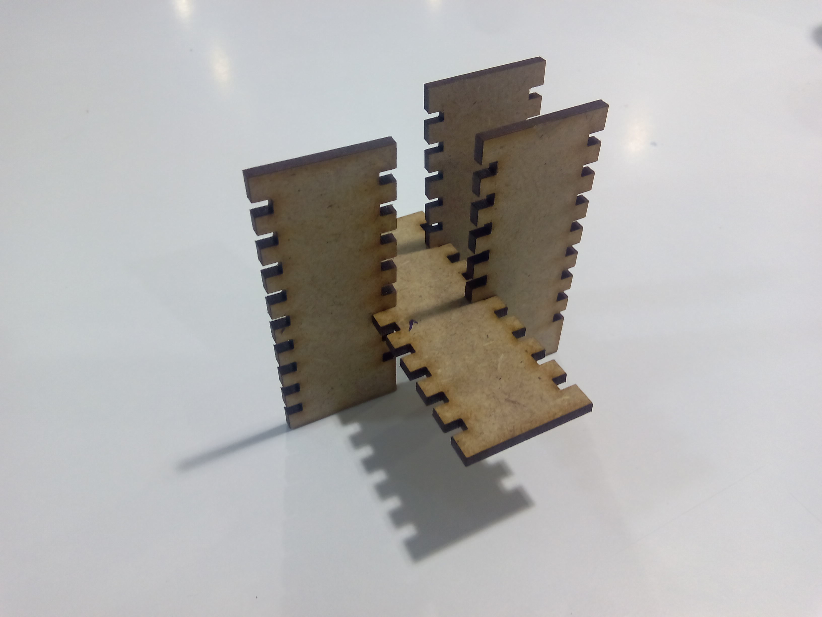
Update: The press fit design developed into two different set of pieces which allow more flexibility. First, a circular joint piece with equally distributed slots and a second polygonal piece with 3, 4, 5 and 6 sides instances.
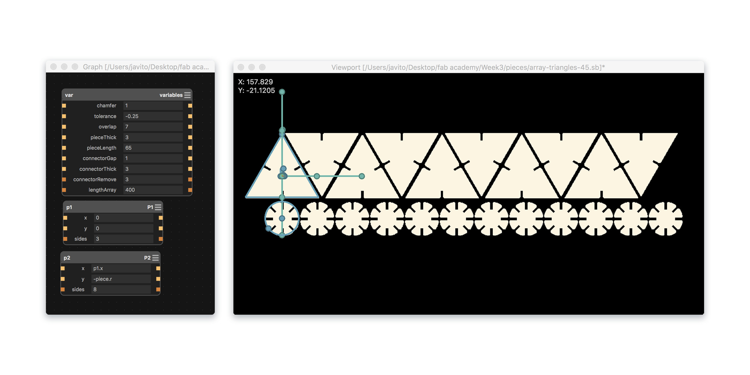
I added a number of extra parameters to optimize the design while laser cutting. Tolerance: an offset of the slot dimensions to compensate the laser kerf and adjust the how tight the connection is. PieceThick and ConnectorThick will help to adjust the design to the specific stock thickness. Overlap is the length of the connection between both pieces, which depending of the overall weight of the larger pieces might need to be increased. And finally, ConnectorGap which keeps pieces apart just enough to allow tight constructions specially for polyhedric shapes.
Fabrication
When using subtractive fabrication technologies you need to pay attention to cutting kerf, the width of material that is removed by a cutting process, this depend on the laser machine and the material so measuring the kerf is always neccesary. As a group task we experimented with different cutting parameters, materials and measured the cutting kerf of Fab Lab Madrid CEU laser cutters, results of this task are described in this page. I worked on the website and made adjustments to the parametric laser test file.
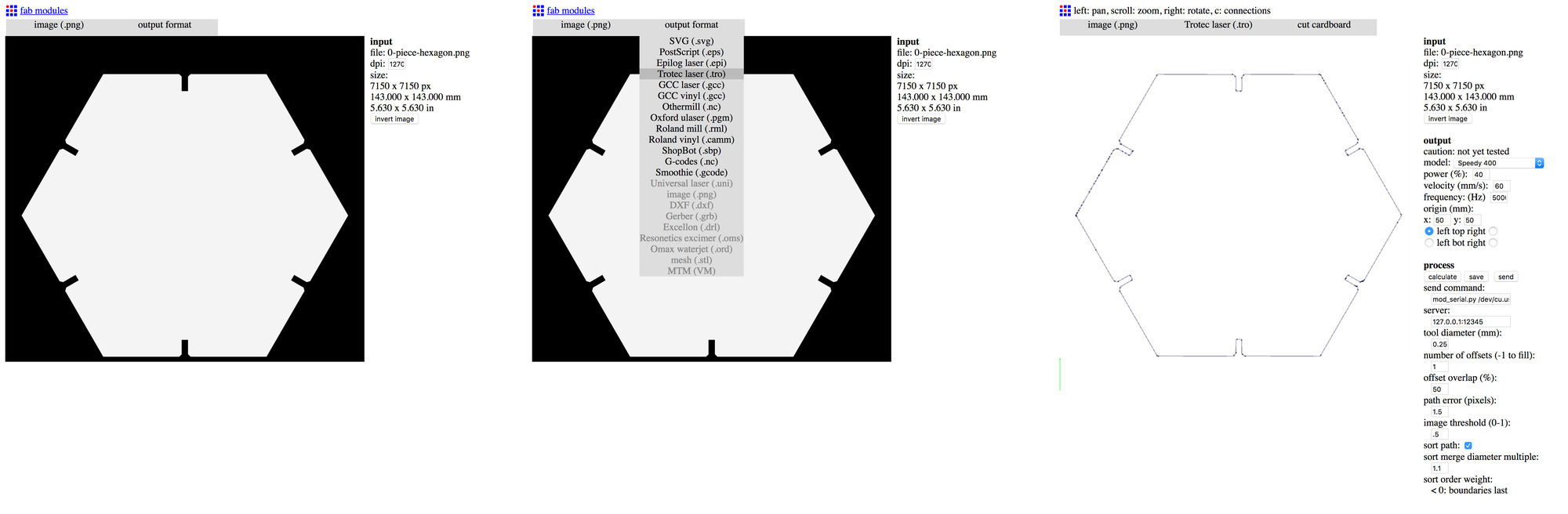
I have used before Trotec's Jobcontrol for controlling Fab Lab Limerick's Speedy 400 so I decided to give a try to Fab modules instead. First you need to install the software in your computer: git clone Fabmodules in your hardrive git clone https://github.com/FabModules/fabmodules-html5.git, then install the node.js dependencies npm install and finally start the server which lets webinterface communicate with hardware npm start.
Once the software is installed, connect your computer to the Trotec via USB and make sure that you write down the used USB address. Then browse to http://127.0.0.1:12345/ and follow the steps:
- Select your PNG image -I choose a 1270dpi, this gives 0.02mm per pixel, repeatability on laser cutters is around 0.015mm- It might be too much though as the resolution is bigger than this.
- Select the output format, in this case trotec laser .tro
- Select the process, in this case cut cardboard
- In the output section select the right model of your trotec machine
- Adjust power (%) and velocity (mm/s), 40 and 60 respectively worked well for me
- Specify the x and y coordinates and position of the relative origin of your image in relation with the absolute origin of the machine bed
- Make sure that
mod_serial.py /dev/xxxx 19200 xonxoffuses the right USB device name - Press the calculate button and wait
- Once the paths are calculated press the send button and laser cutter will start cutting
The fabrication process was straight forward. Testing and adjusting tolerance, overlap and connectorGap parameters until I was entirely happy with the snap-fit joint. The final values were:
- Tolerance= -0.25mm This value compensates the laser kerf and creates a very tight joint
- Overlap= 7mm I needed to increase this value from 5mm to 7mm so the bigger pieces would fit best.
- connectorGap= 1mm I had this originally at 3mm but 1mm worked best at the end.
- The kerf on our Speedy 400 and this type of cardboard was 0.12mm
Group task
On the group task we did cut a number of materials and tested the right speed and power settings although cutting kerf wasnt properly measured. My contribution of this group task was to code the website and adjust the parametric design made by Pilu. I managed to measure the cutting kerf on Fab Lab Limerick's Speedy 400 but only on the corrugated cardboard that it was used for the press fit design. Since then I have had a look at some gauge designs for our fab lab users so they can measure the kerf more easily.
The original test file was not designed parametrically so we decided to do a Antimony sketch with a simple parametric object of 2 by 5 cm with slots.
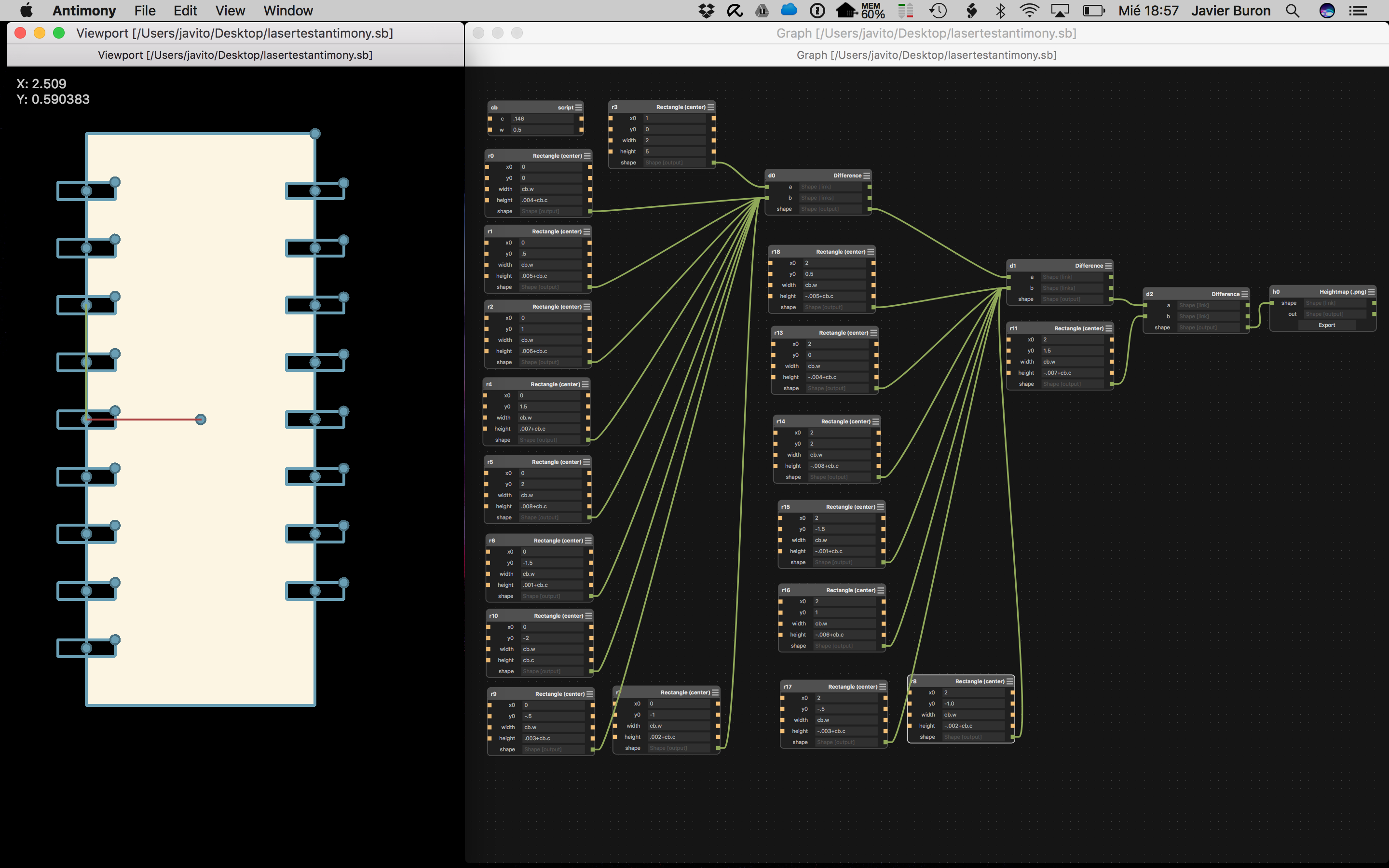
On the left side incrementing the width of the slot by 0,01mm from bottom to top and or the right side decreasing the width by 0,01mm. This would allow us to measure the kerf of the laser cutter and the right parameters for a snug press fit joint.
Third assignment B
Vinyl cutting
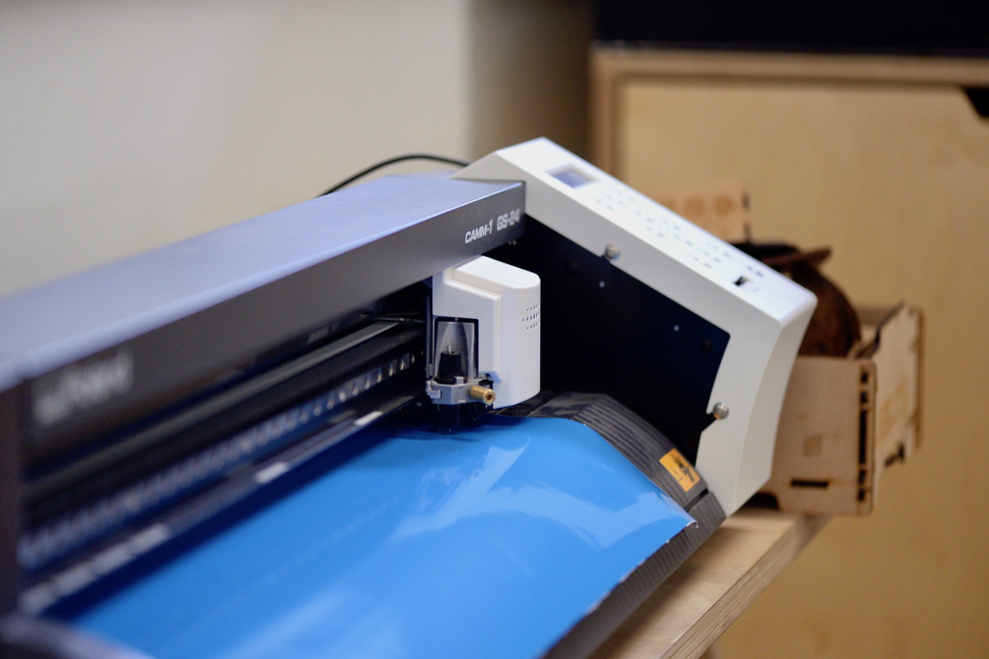
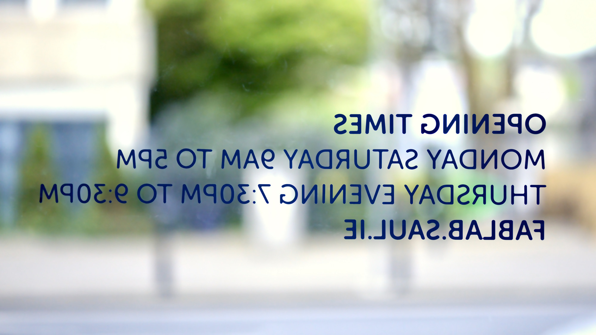
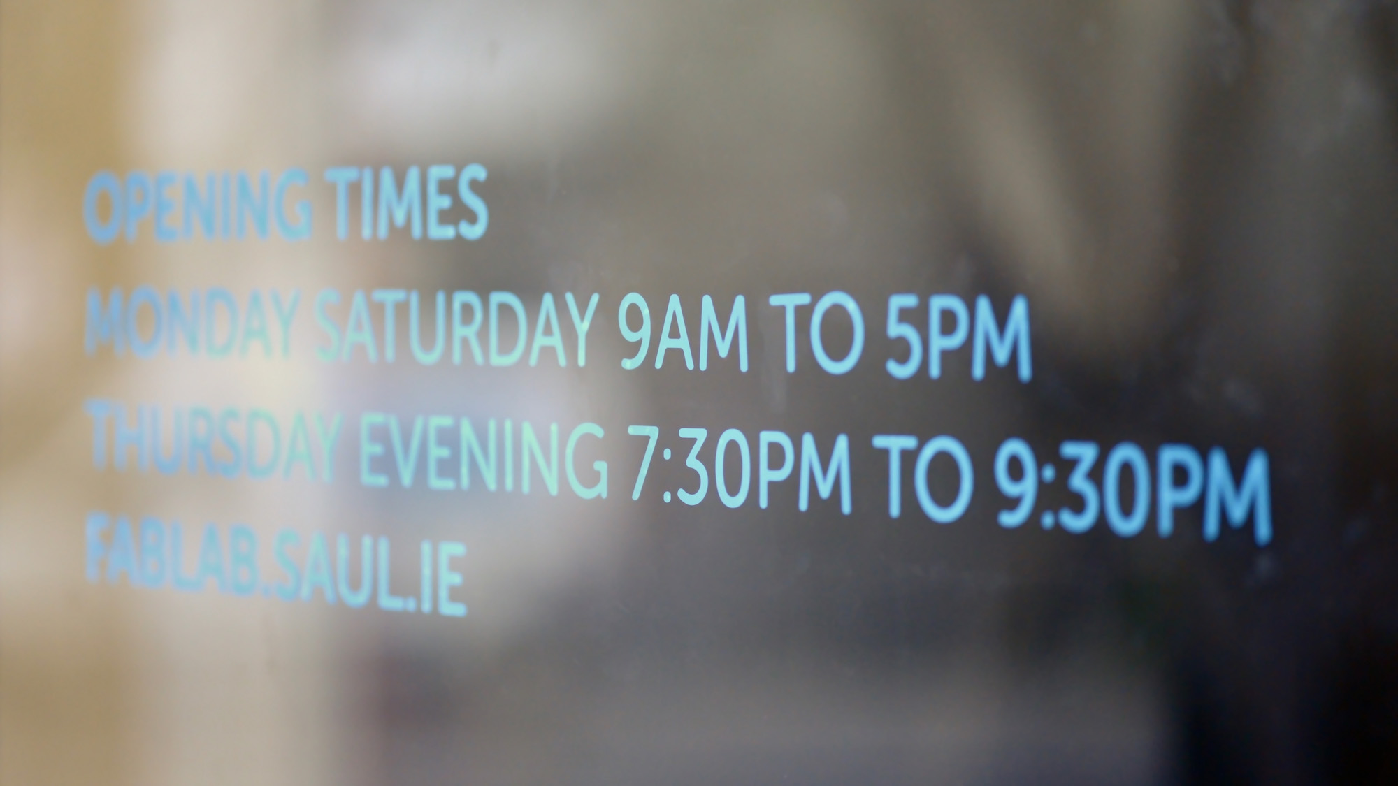
The second part of the assignment was to cut something with the vinyl cutter. I decided to cut Fab Lab Limerick opening hours for displaying at the lab's entrance.
Our vinyl cutter is a Roland GS-24 which unfortunately doesn't have good support for macs. I tried to use the vinyl cutter with fabmodules in my Mac without much luck. Problem seems to be related with the printer driver necessary to use LPR, in Linux a generic Raw printer driver installed using CUPS seems to do the trick but the same driver on a Mac does not work with fabmodules. I will try to do some research to solve this issue.
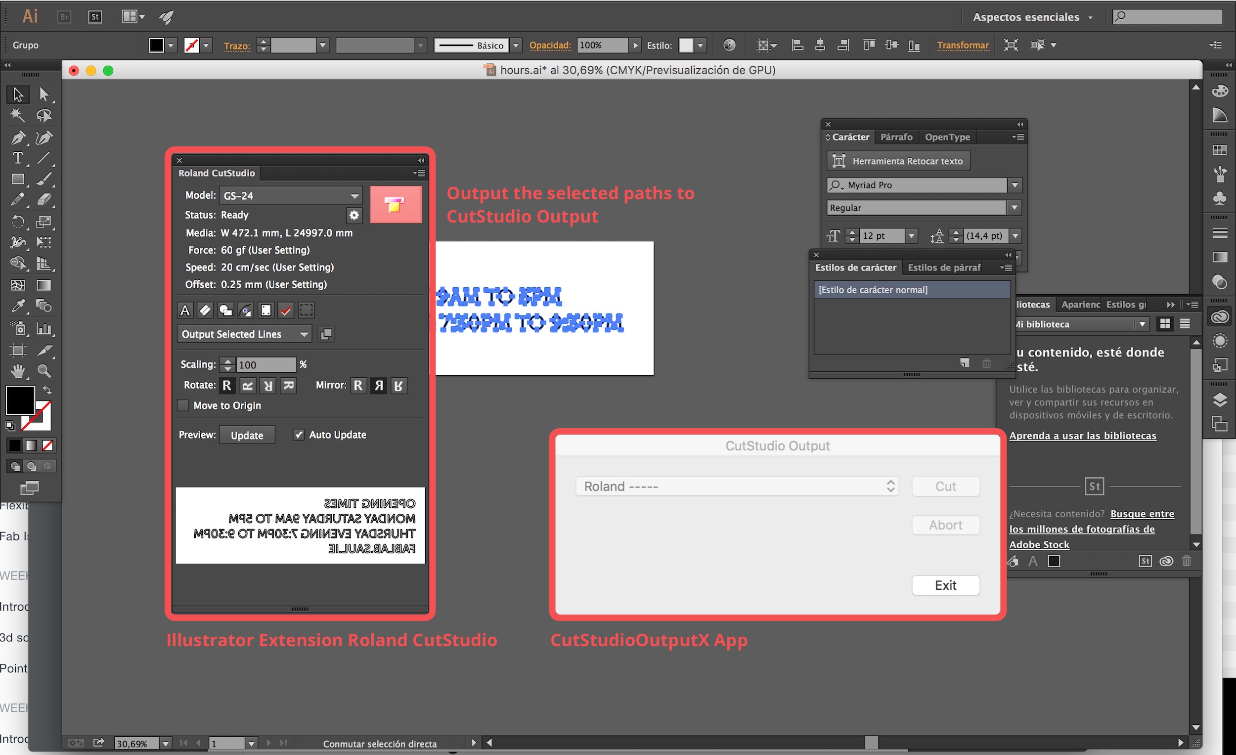
I was forced to use the awkward solution that Roland gives to Mac users which is an Illustrator extension together with a piece of software called CutStudioOutputX. Once everything is installed vinyl cutting with Illustrator and CutStudioOutputX is quite straight forward. Select the geometry, setting force (60gf) and speed (20cm/sec) –tried this settings first at the machine using the test buttom– settings and press the cut button, this will send the drawing to CutStudioOutputX and from there send to cutter again. Signage was cut in less than 5 minutes.
Once the cutter has done its job the next step would be to remove all the background vinyl leaving just the letters alone and peeling off all the excess vinyl. If the force and speed settings were correct it is time time-consuming but simple enough process, I had to use a blade on a couple sharp and small corners that were not cut properly.
After this, we need to transfer the vinyl to the transparent adhesive roll carefully unrolling the adhesive transfer on top of our vinyl, be carefull with air bubbles and wrinkles!
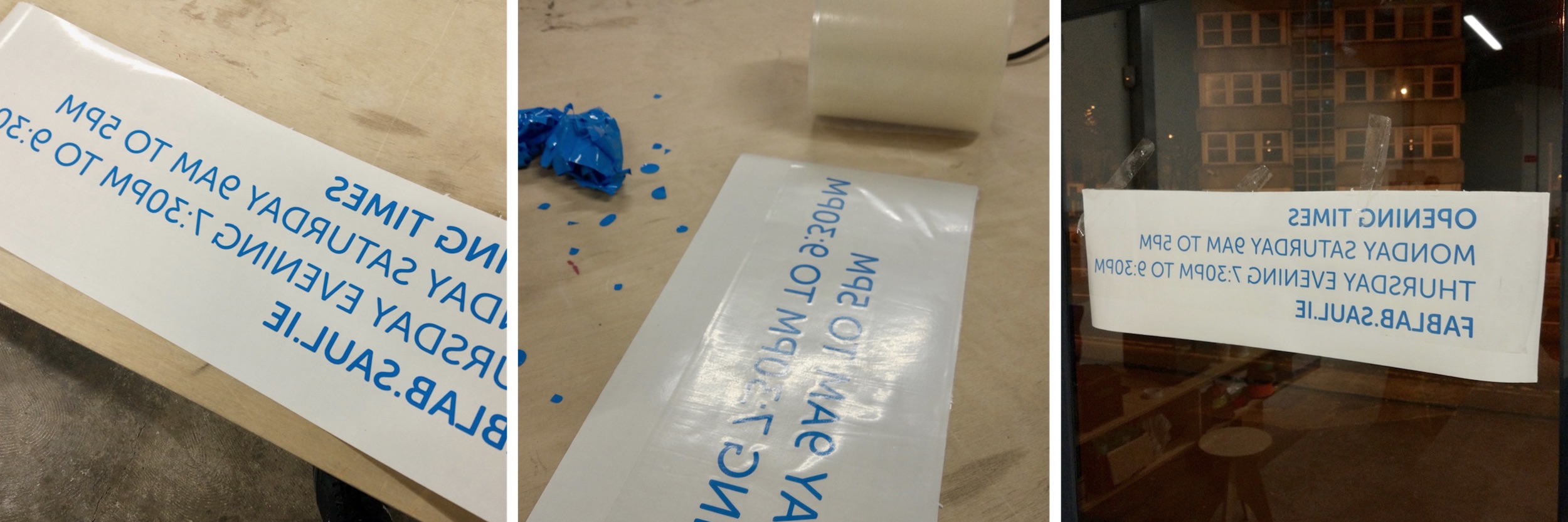
Finally we need to place the vinyl onto the desired position and carefully peel off the white back of the vinyl while we glue the letters on the glass surface. Take your time and do not rush when doing this process.
Avobe you can see the final piece, one of the M's fell down when peeling the transfer but it was easy enough to put it back in the right place. Can you figure out which one is it? 😉
Assigment files
Laser cutting
Antimony files:
- Joint modelled in Fusion360
- Triangular pieces and 45 degrees connectors Antimony
- Square pieces and 60 degrees connectors Antimony
- Pentagonal pieces and 72 degrees connectors Antimony
- Hexagonal pieces and 60 degrees connectors Antimony
Vinyl cutting
SVG file: