Composites
Read the material safety data sheet (MSDS) and technical data sheet (TDS) for the resins and hardener that you're using
Design and make a 3D mold (~ft2 /30x30cm), and produce a fiber composite part in it
Learning outcomes:
- Demonstrate workflows used in mold design and construction
- Select and apply suitable materials and processes to create a composite part
More Evidence:
- Shown how you made your mold and created the composite
- Described problems and how you fixed them
- Included your design files and ‘hero shot’ photos of the mold and the final part
- Read and linked to the material safety data sheet (MSDS) and technical data sheet (TDS) for the resins that you're using
Overview
Composites are an interesting area of construction. Something about putting epoxy on burlap feels almost antithetical to cutting-edge construction; however, it is clear why this method works. The lessons learned about tension and compression in tiny balsa wood bridges, from middle school shop classes, illuminates these ideas. Use the fibers for tension and the resin for compression. Extending this week’s work to some of the more advanced composite combinations, such as carbon fiber and hazardous resins, in large autoclaves feels more like advanced fabrication.
What to Make
For my work this week, I decided early on that I wanted to see two things: (1) the resolution limit of composites and (2) more experience with true 3D milling on the ShopBot. My final project does not really need any composites, or at least I could not conceptualize their use in the project before this week, so I had no intention to try to integrate this week into the final project. Instead, I decided to build something that is purely aesthetic: a composite model of Mount Adams, in Washington, USA. I climbed this mountain in 2014 and knew that its volcano shape meant that it should machine nicely and look striking, as in real life. Truth be told, I wanted to mill Mount Shuksan. However, I had some difficulty finding Shuksan’s 3D data for the processes this week. If I had a little more time, I would have explored getting elevation data from USGS into an STL file on my own. Instead, Mount Adams had STL models that were readily downloadable on Thingiverse that I could use for this project.
Choosing to mill a composite mountain would help me qualitatively determine the resolution I could resolve with composites, because the level of detail that they final product produced on the top and bottom layers could be compared to both the manufactured tooling and original data. Obviously, the detail of the tooling will play a large part in determining the detail of the composites, so the composite-tooling comparison is essential. Comparing the outcome to the original STL data will be more useful for establishing accuracy, rather than precision. All of this comparison is purely for my own curiosity and the knowledge base at my local lab. This will not be proper original research.
Building the tooling
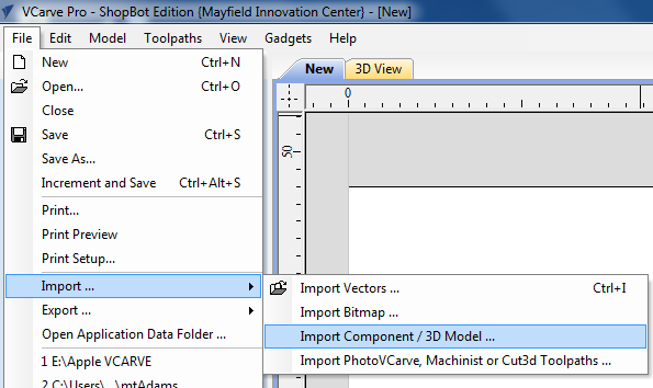
Once I had located an STL file that represented mount Adams in 3D, I could import it into vCarve for milling on the ShopBot. The file imports nicely, but was designed at life size, so it clearly needed scaled down. The limiting size here is primarily the height of the mountain, and only because of the height of the material I would be using for the tooling. Making or finding appropriately tall foam board turned out to be a struggle all on its own.

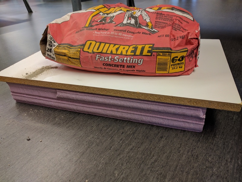
I had a large amount of 1.5 inch hard foam in my lab, so I had hoped to glue two pieces together to make a 3 inch tall piece of stock. That didn’t go well. I used wood glue, and it never properly stuck. I sat on the foam, put weights on the foam, and after several hours: it had simply not started to adhere. Perhaps another adhesive would work better, but I know that some adhesives will also eat through the material. Not knowing the secret trick to stick two sheets together; I went to Home Depot instead, and bought some 2 inch rigid foam. This would just fit my mountain, and leave a little bit of space at the top and bottom for extra material removed and left, respectively. If I had a taller stock, I could stretch the mountain STL vertically, but not with this material.
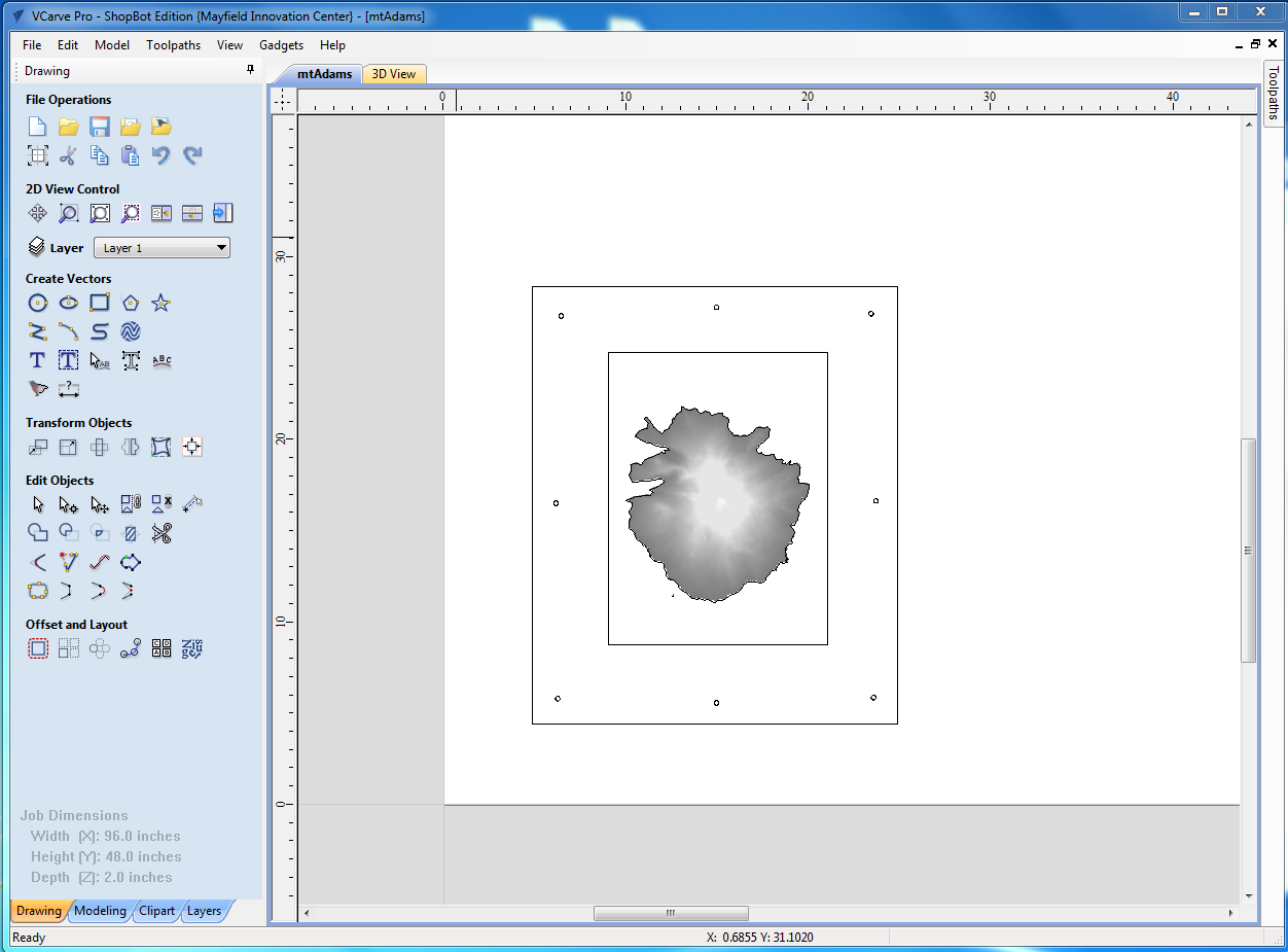
The transition from an STL to a set of toolpaths is critical as an element of the Fab Academy learning goals. In vCarve, I did a series of things so that I could get the tooling designed as I wanted it to be. The first step was to setup the material for the job and, in my case, this was the 2 inch tall stock as well as the 48x96 inch area of the bed. From there, I imported the STL of Mt. Adams. The mountain needed seriously scaled down, but that was a simple scaling. One interesting issue was fitting the mountain into my desired size for the composite part. I wanted to make the composite be able to fit into a 12x16 inch picture frame. This meant that I had to cut off the lower extremes of the mountain, so that I could get some appreciable height and not overfill the frame. (This cutoff ended up being at about the 5000ft of elevation line.) At this point, I had a properly trimmed STL in vCarve, that generally looked the way that I wanted it to. I set some simple boxes around the mountain, so that I could cut it out and see the general size of the piece I was working with.
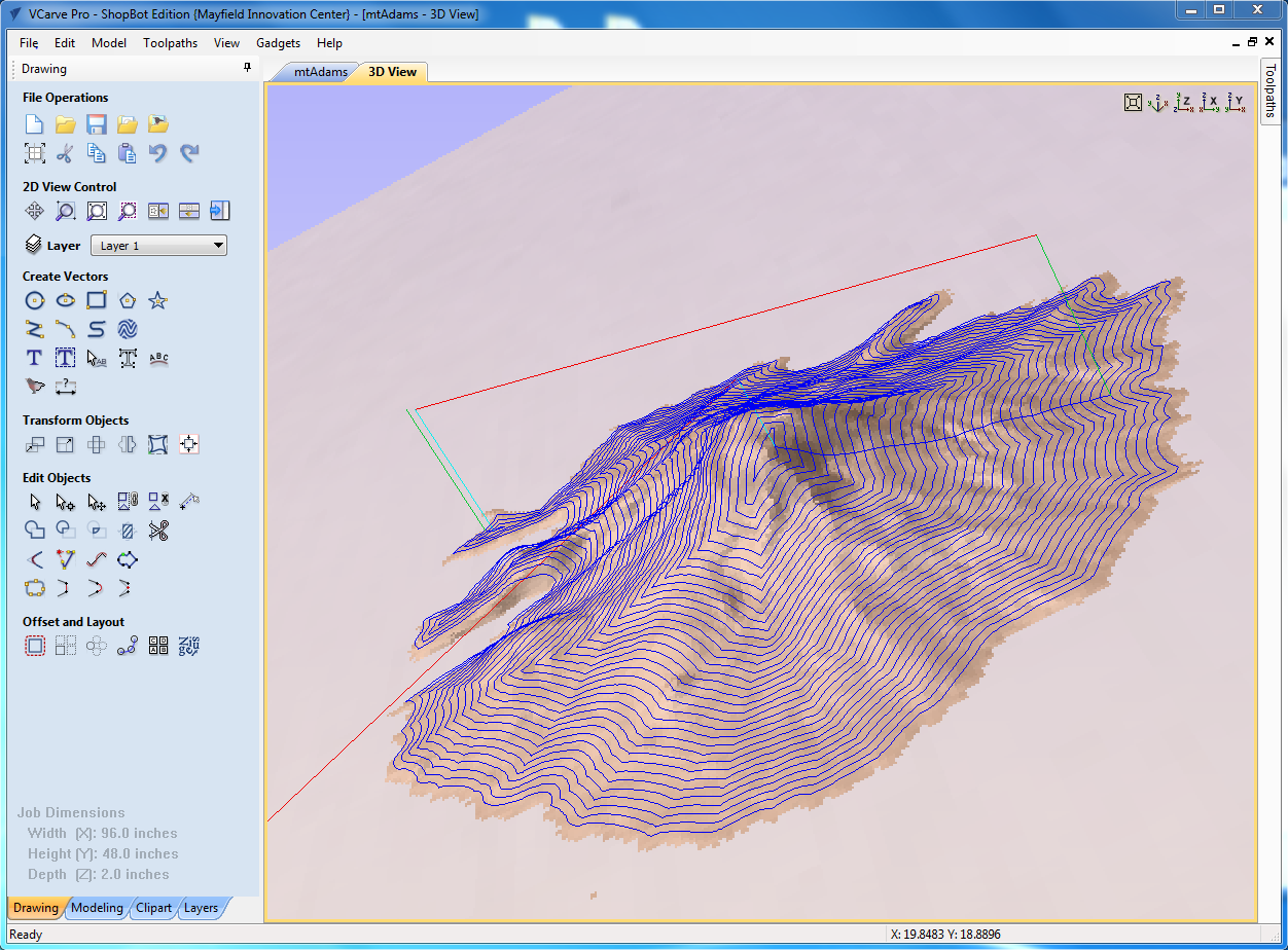
One step I had not anticipated before I started was what toolpaths I would need to generate. After a bit of playing around in vCarve, it became clear that I would need several toolpaths for different parts of this job. I started to explore the 3D milling process for over the mountain. vCarve has a rough cut and finish cut toolpath option for 3D milling. I generated both, and it was clear that they should work, based on the simulated toolpaths shown on screen. I used all of the standard speeds and feed in vCarve, since they had always worked well. It is possible I could have gained a little time by adjusting settings, but this didn't seem to be worth the risk of screwing anything up, for this week's work.
The following table can serve as a quick reference guide for the speeds and feeds that I used with the bits that were included in making this week's toolpaths. The 1/8" ballnose was run at 25% overlap between passes, and then 50% overlap between pases to get a nicer finished look on the mountain. a generally nice reference table is located HERE.
| Bit Used | Spindle Speed | Feed Rate | Pass Depth | Step Over |
|---|---|---|---|---|
| 1/4" downcut with two blades | 15000 RPM | 4 ips | 0.25" | 25% overlap in cut |
| 1/8" tapered ballnose | 15000 RPM | 2 ips | 0.125" | 25% overlap in cut |
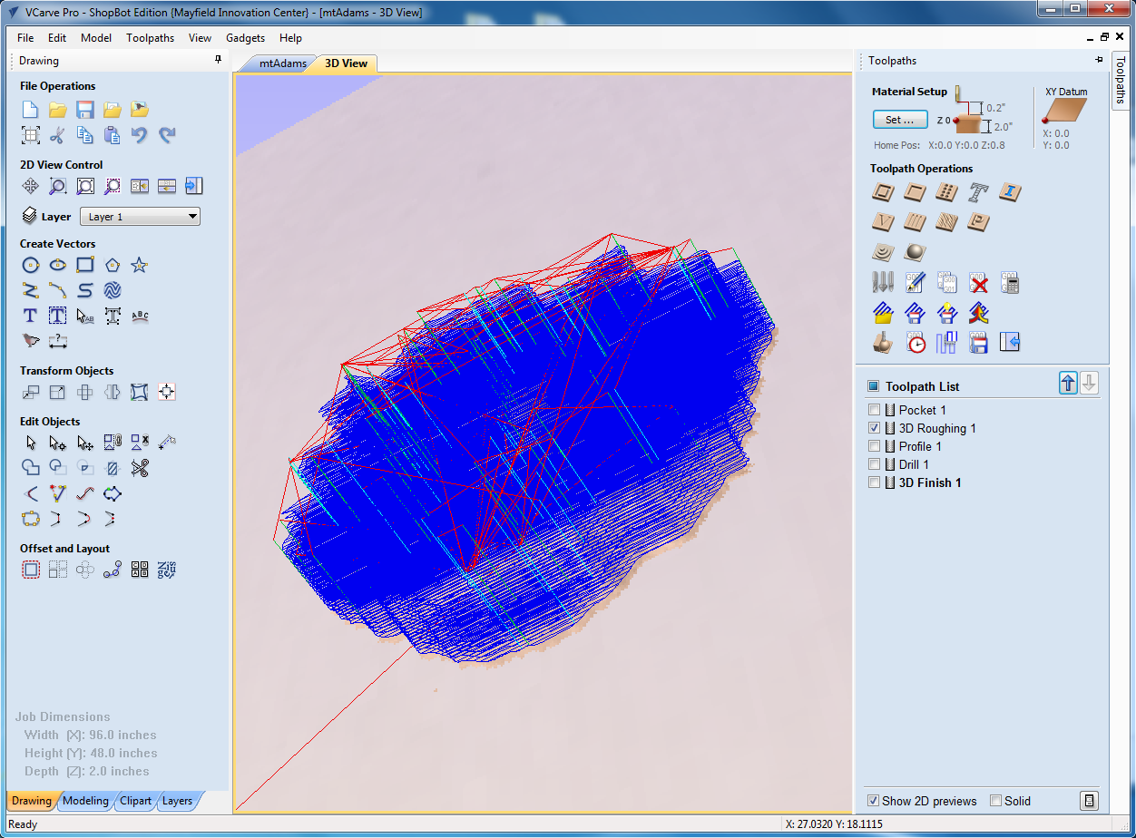
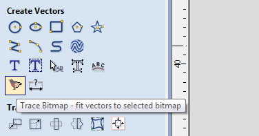
However, I needed a new trick to make sure the area around (and not directly over) the mountain was also cleared of material. The useful element here turned out to be the oddly depicted feature called ‘trace bitmap.’ It seems bizarre that the GUI symbol for this is a bird being outlined, but it is useful. I was able to select Mt. Adams and have this utility find the edges of the STL. From there I could make a simple pocket toolpath in the area bounded by the 12x16 inch box and the mountain’s edge. This ended up giving me a nice toolpath that would clear the area around the mountain and get things ready for the cutting of the mountain itself. I figured that it would be best to have this waste material out of the way before starting on the mountain.
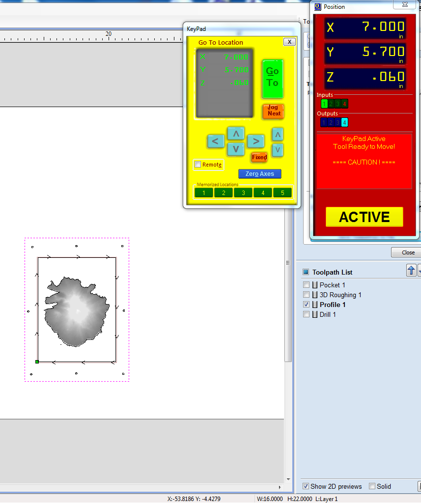
Another detail of setting this job up on the full area of the Shopbot, brings up one major positive and negative of the strategy. Positive: You can have the machine zero its own X and Y axis (which means you can’t loose these if the power dies). Negative: You have to align the toolpaths you generate with the piece of material that is actually placed on the ShopBot. This set-up can be done by giving yourself a feedback loop between the planning of your toolpaths in vCarve and the placement of the material in the ShopBot control software. This process is depicted to the right, and you can use the end mill and onscreen readouts to align the vCarve toolpaths to make things go well. Alternatively, you could design all of the toolpaths to be scaled to the material, and then zero your X, Y and Z all to the material on the ShopBot bed, but I’ve lost jobs to power failures or user errors in the middle of this process that disoriented my calibration.
To cut this on the ShopBot, I generated several independent toolpaths, with the two different end mills mentioned above. These toolpaths each had a purpose:
- preview the outline of the material (to confirm placement)
- show where I should sink screws into the material
- cut out a pocket area around the mountain with a large mill bit
- rough cut the shape of the mountain with a fine mill bit
- detail cut the shape of the mountain with a fine mill bit
- cut out the 12” by 16” area from the rest of the stock
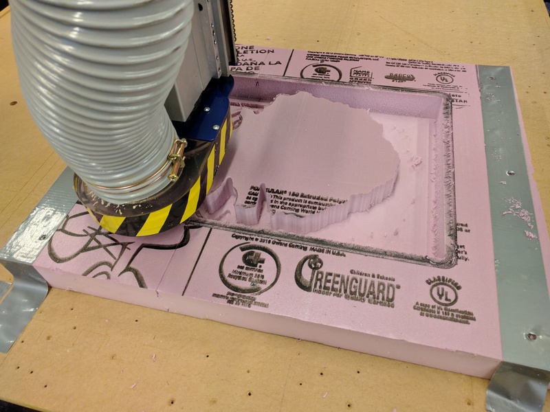
An important side note is the vacuum process for the ShopBot. When using this tool, and removing this much material through subtractive manufacturing, you need to get it out of the cutting area. For this, our shop has a large floor-standing vacuum hooked up to the ShopBot via a 4-inch hose. It may not be the most glamorous part of the job, but it is necessary.
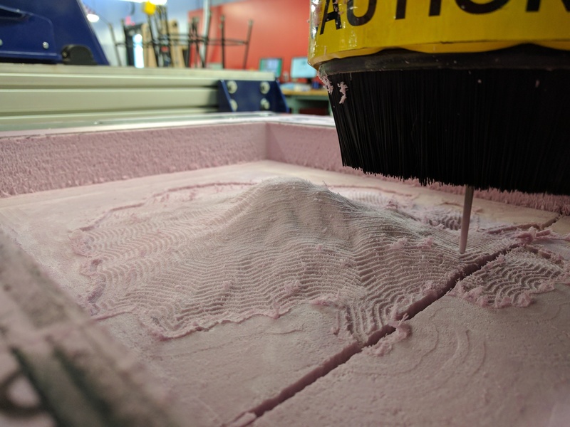
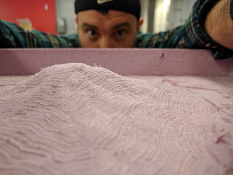
It turned out that I did not run all of those toolpaths as I had originally planned. Everything went according to plan until step 4 above. (It is worth noting here that rough cutting the mountain with a fine bit was a huge mistake. It took nearly three hours just to run that one toolpath. I should have stuck with the larger bit for the rough cut of the mountain.) After the detail cut of the mountain, there were several artifacts of the ball nose 1/8th inch mill bit leftover. To try and reduce this, I changed the step over in vCarve to 50% and ran the detail cut again. [step toolpath 5 above] After this, the mountain turned out much nicer and could possibly serve as a good piece of tooling to test for detail in the composites. I never can the fifth toolpath above.
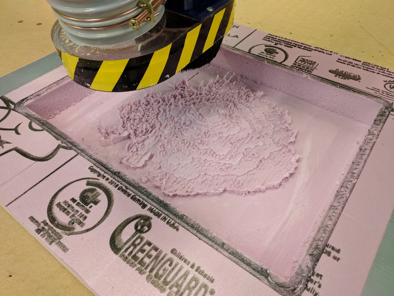
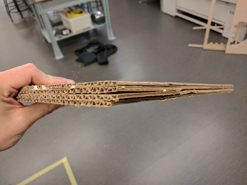
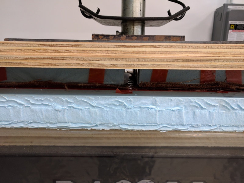
After finishing all detail cuts, everything looked good. Except for one problem: The milling had cut into the perforation that is a part of the rigid foam insulation. I essentially lost a stripe of my tooling as a result. To try and combat this, I did a few things. First, I made a backing for the tooling out of cardboard. This would help with tooling rigidity. The plan became making 4-ply cardboard backing, taking care to run the sheets perpendicular when I could. Alternating directions adds to the rigidity of this ply-cardboard and these sheets could be easily adhered. The four sheets went together nicely (after I screwed up once and did not alternate the ply directions). Cardboard’s porosity also meant that it worked well with wood glue. This panel was attached to the back of my tooling before removing it from the rest of the foam stock. The extra stock was all that held the tooling together until the cardboard backing was added. To finish the piece, I waited for the cardboard to adhere to the back of the tooling and then cut off the excess foam with a band saw.
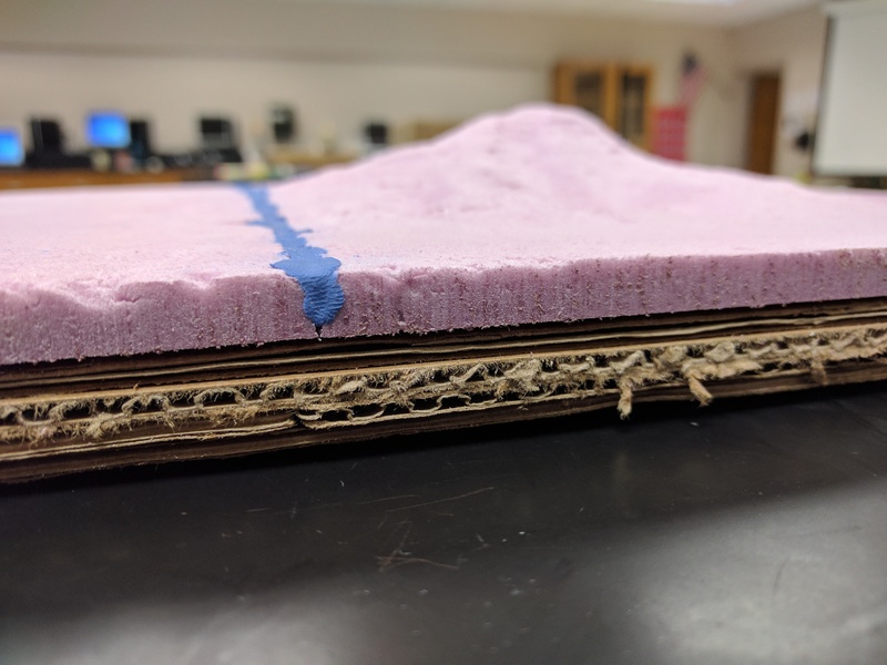
The large perforation running across the model also added another complication: I had a significant portion of my tooling that was missing. When my roommate saw this for the first time, he asked: “Is there an oddly straight river going through the Mount Adams?” An appropriate question given the look of the tooling, but a problem I would need to solve. At this point, I knew that I intended to vacuum bag my model. I needed to fill that void with something that could withstand 15PSI without deforming too much, and that could be easily molded into the needed form. Modeling clay seemed an obvious solution, and I just hoped that it would not deform too much in the vacuum bag. This seemed reasonable since the clay would not really have any place to move out of position when in the vacuum. [The modeling clay turned out to be a serviceable solution.]
Building the Composite
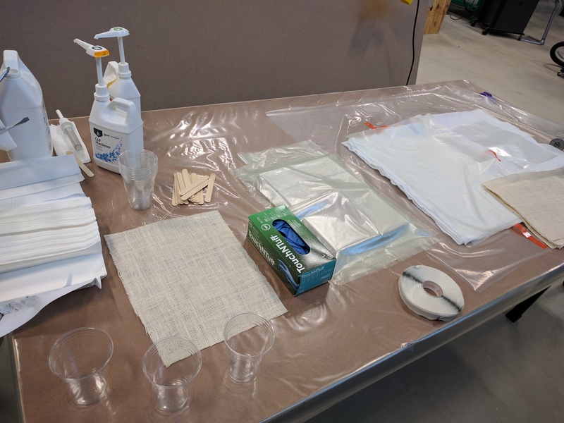
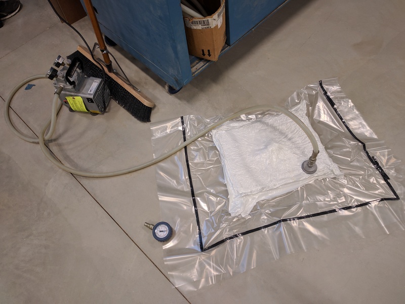
I obtained white burlap and muslin, on sale from Joann Fabrics. These two materials would be the tension members in my composite. Super Sap CLR epoxy resin would be the compression member, and my lab had the fast hardener to use with the resin. The burlap and muslin was laser cut so that it could fit the tooling closely. I cut out all of the needed layers of film, burlap, muslin, wicking, bleeder, masking, breather and vacuum bag material by hand. I arranged these on a 4’ by 8’ piece of plywood covered with plastic. Before any of the resin and hardener was mixed, I took care to lay things out in a sensible workflow. I prebuilt everything I could for the vacuum bag and laid out all of my layers so they could be quickly assembled. A little experience (outside composite work) has taught me that any construction job goes better if there can be a sensible flow to the work area.
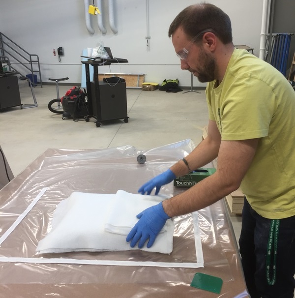
At this point, I mixed the resin and hardener. The volumetric press-pumps at LCCC were broken, so we mixed the resin and hardener by volume in the needed 2:1 ratio. Paul O’Niell mixed and dumped the epoxy onto the burlap, and I spread it out with the squeegee and placed it on the tooling. Once we had saturated all of the layers with epoxy and stacked them on the model, final alignments were made. The many layers needed for the vacuum bag could then be assembled and the vacuum pump turned on. Everything from the first epoxy mixing to the vacuum bag turning on took less than 20 minutes. Well within the pot-life of the epoxy we used.
The vacuum bag process was fascinating, in that it seemed thrown together. The ‘bag’ as really a plastic sheet I taped closed over itself. The vacuum process requires a vacuum pump, and specialized fitting that will hold on to some thick (but not rigid) plastic sheeting. This sheeting must be above and below the composite, and extend far beyond the part’s edges. While I was setting up the part and coating things with epoxy, all of this work was done on one half of the plastic, as though I were making a very large and unappetizing burrito. At the completion of the epoxy process, I simply laid down a strip of foam tape, and closed the plastic onto itself to make the bag. The vacuum was then applied to the system through the fitting and left overnight so the epoxy could set-up.
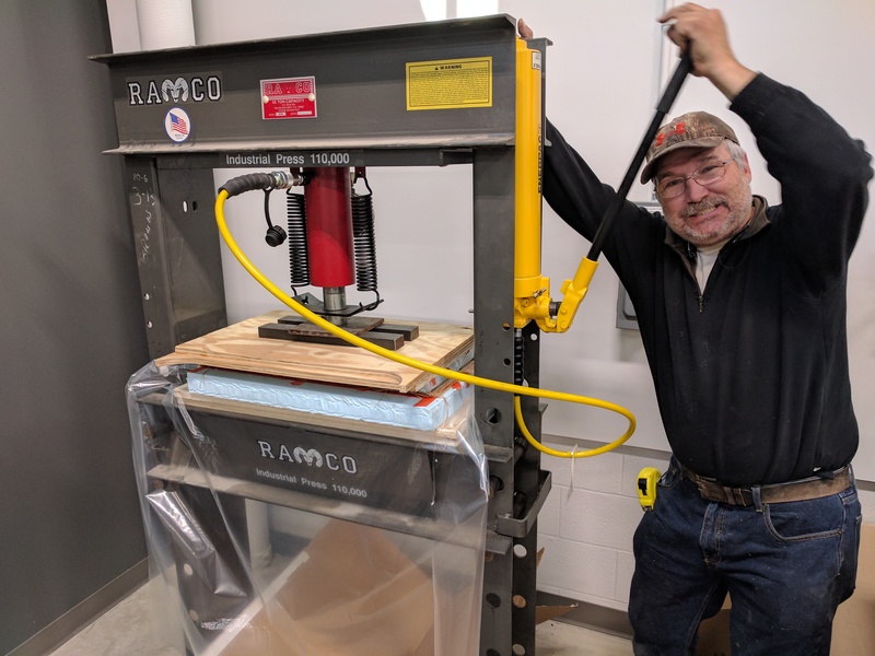
I also helped Paul with his epoxy process, which he followed by pressing together in a two-part mold. I was happy to get to see both processes used, as they are substantially different ways to apply pressure to the molds.
At the time of writing this, I have not seen the finished composite. It has cured for over 24 hours in the vacuum, but I have not been able to be back in the lab to see the result. I will update this page with the hero shot once it has been taken. Below is a Flicker album that will be more fully integrated into this page at a later time. (My high school students are all quickly approaching graduation – it is a very busy time for me outside of Fab Academy.)
======================= UPDATE ===============================
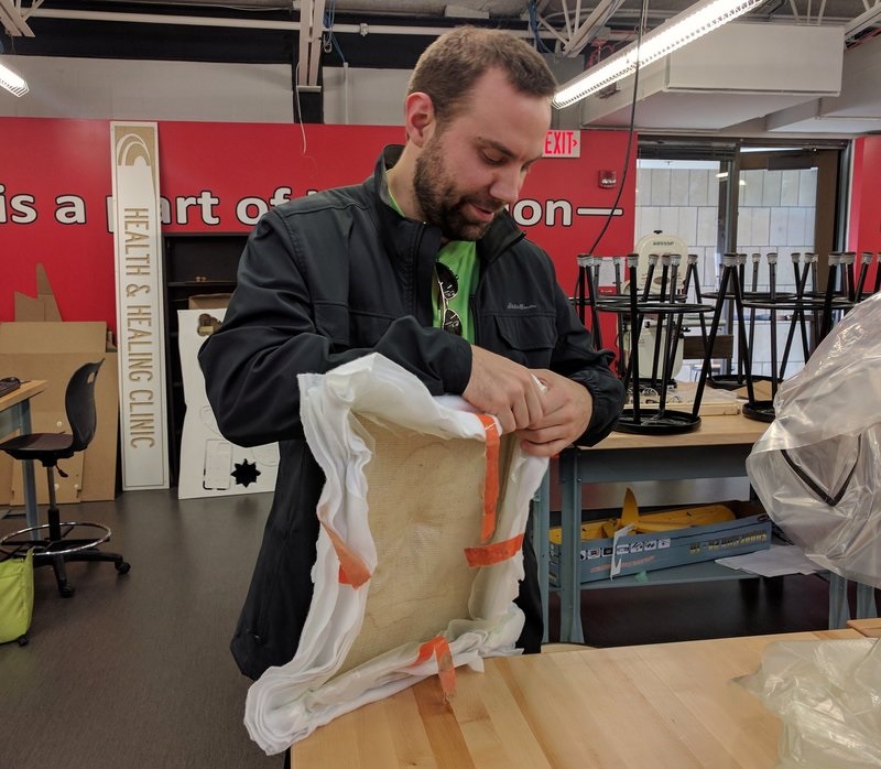
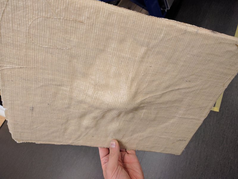
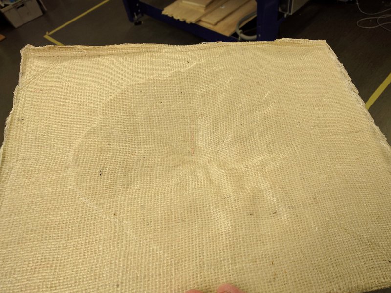
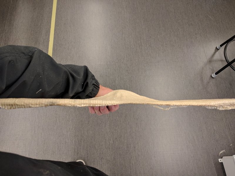
The final version of the composite turned out nicely. The shape of the mountain is clearly visible on both sides of the composite material, but there is more detail on what is the ‘underside’ of the mountain, rather than the top. Perhaps I should have made the negative of the mountain for my tooling and done the composite over that, to get more detail in the final product. Another artifact of the vacuum bag process and lacking a hard/ wood backing was that the entire piece warped a little bit. The edges all seemed to curl up a small, but noticeable amount. Also, extra material wrapped down around the tooling and made it difficult to demold. I ended up cutting off these edges with a band saw to try and clean up the edges. Once Fab Academy is over, in intend to paint and frame this piece as a map and piece of wall art – I want to map out the path I used to summit this mountain in 2014.
You can see all images (used and unused) from this week's work HERE.