The first idea that came up to my mind was having a robot assistant that would follow me around wherever I go and assist me in carrying stuff when needed and I was lazy of carrying my stuff around like in supermarkets and etc … So I had in mind of a robot that follows me and can be in the shape of a wagon , cart , giant truck , or even a small toy that small children could have fun playing with. Implementing this idea in our daily lives was my dream. So I started thinking of how would the robot follow you ? What’s so unique in a human that I can program the robot to follow ?
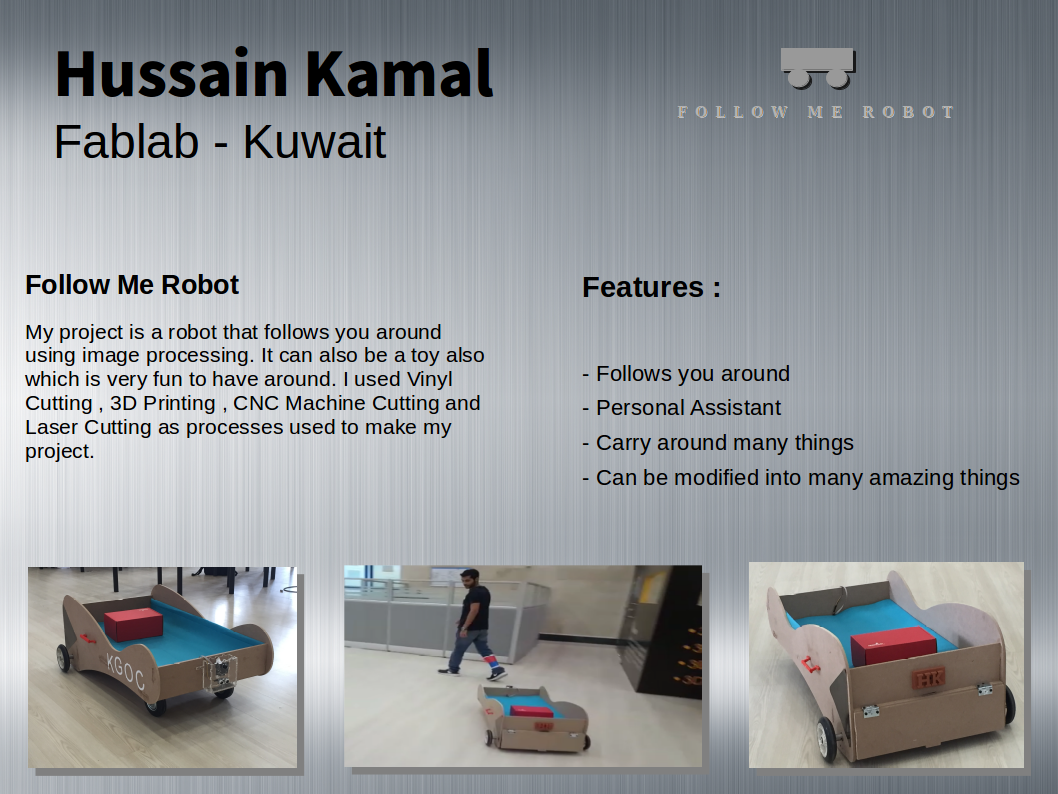
Features :
- Follows you around accurately
- Could be designed as small toy or even a giant wagon
- Carry many or heavy things for you without any effort
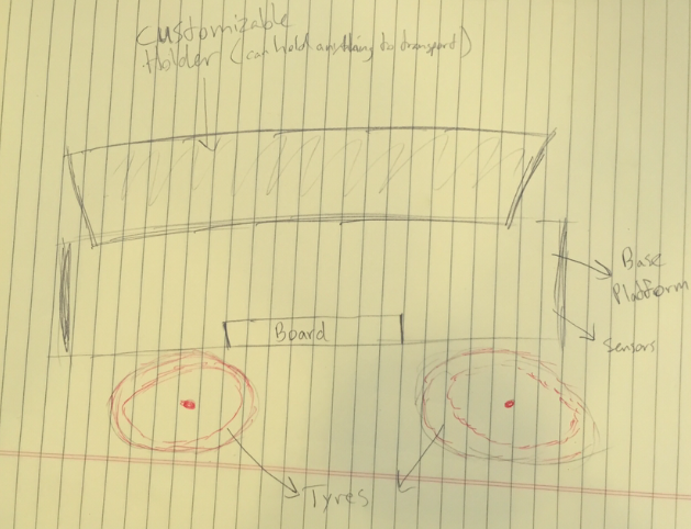
Sketch :
Below is primary rough sketch of my project that I drew in January when I first joined the Fablab.
Future Developments :
-Add GPS and internal GPS for supermarkets by defining the whole place and using the codes and programming to select any item with fixed ipad, and it will take you there.
- Add fire detector to follow fire and extinguish it.
- Add a toolbox and becomes a following tool box helpful for garages and labs.
- Modify it to become a boat to follow the the wagon when loading the boat from the water back to the wagon. Reduces accidents of loading boats.
- Add a baby cart so it becomes a following baby cart, very handy for parents while walking or jogging.
- Make a baterry place on the ground and program to go automatically back to recharge wireless when battery is low.
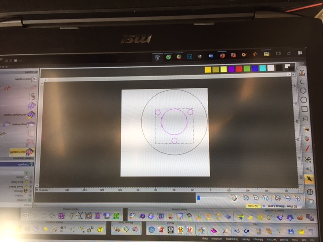
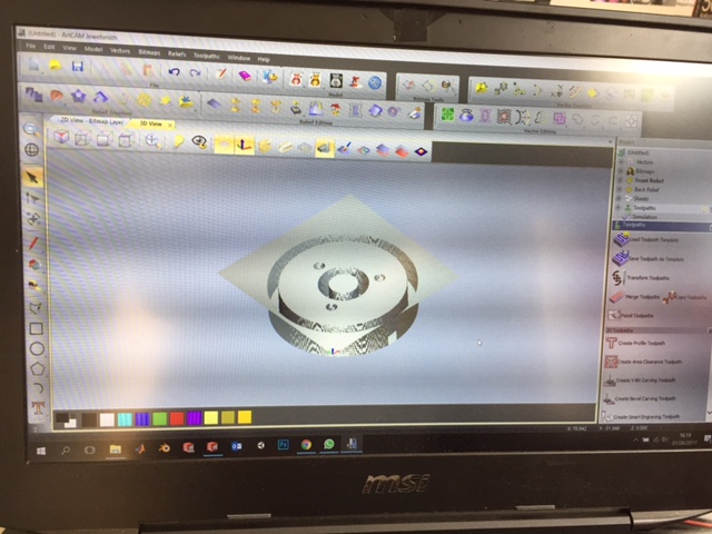
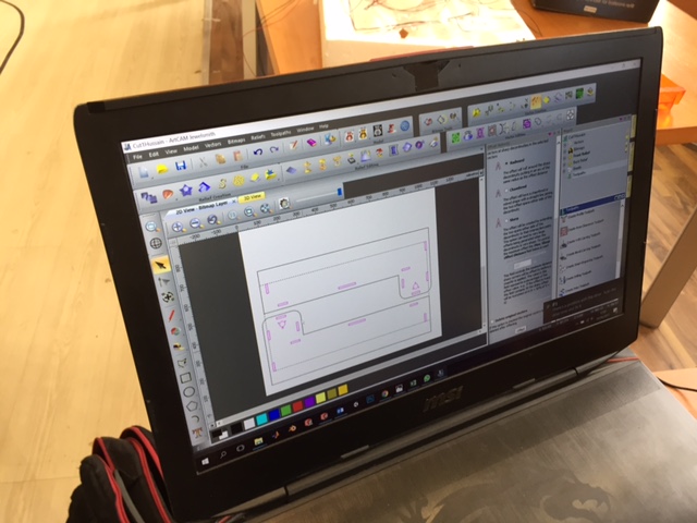
Then imported my design in ArtCam software to cut.
This is how it will look like in the wooden sheet.
CNC Cut :
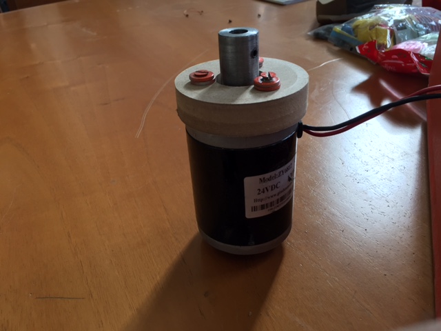
Then cut my design and fixed it on the DC motor which fitted exactly on the first attampt.
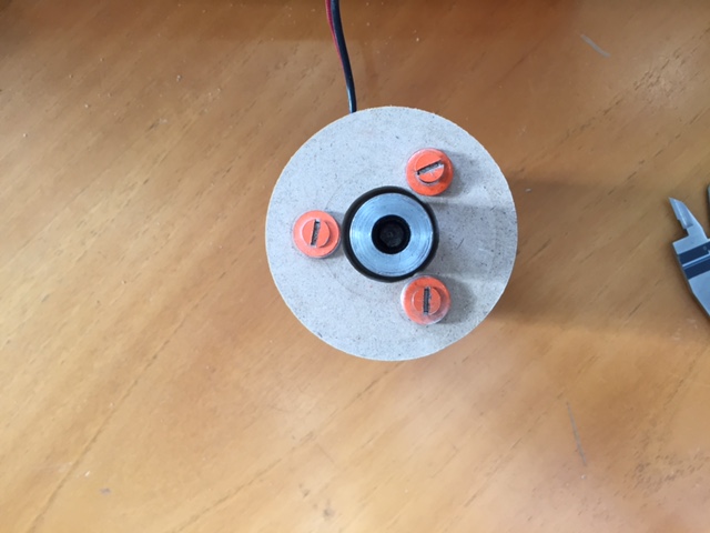
This is a view from top to show how accurate the measurements I took.
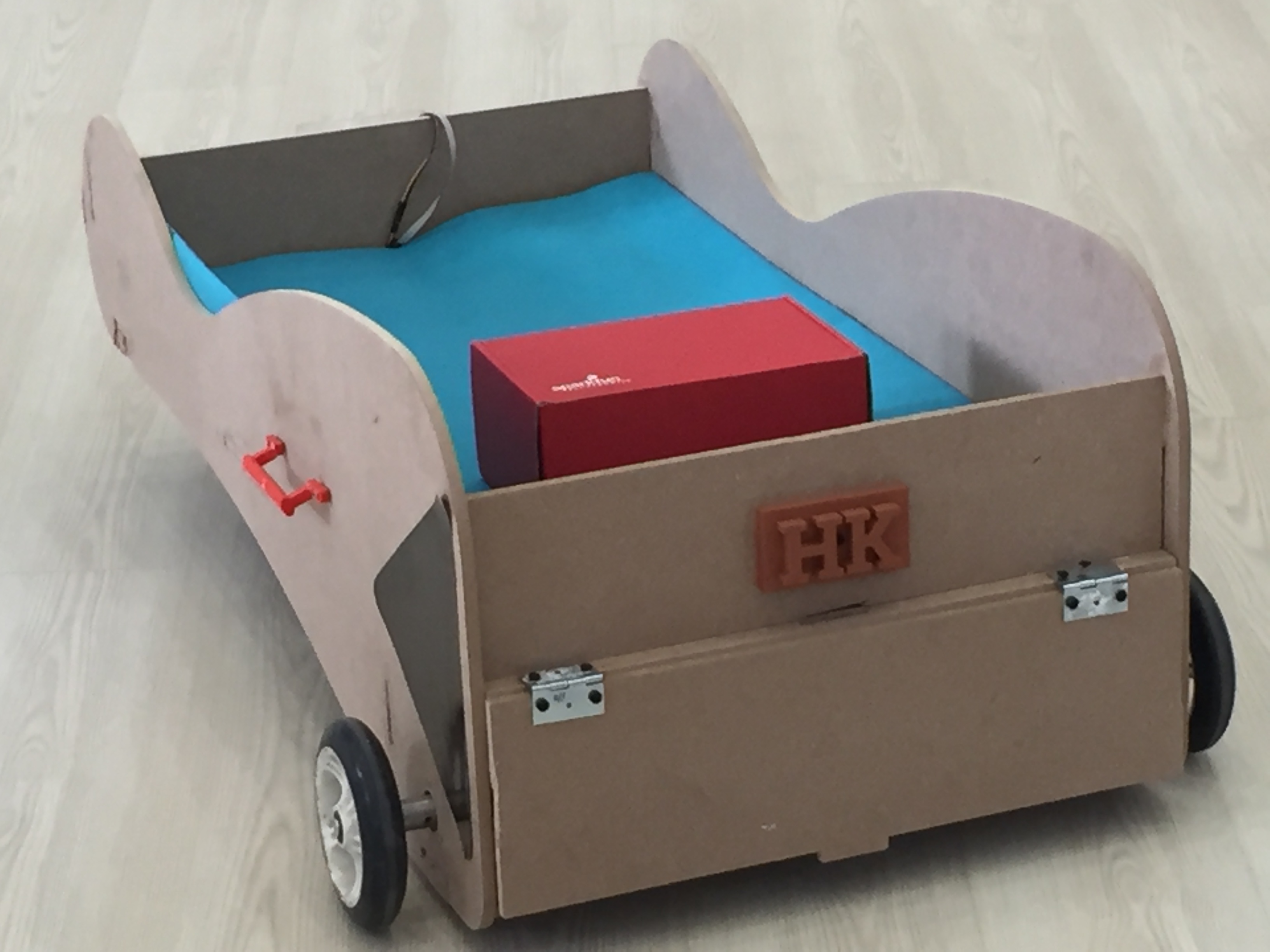
Final Project Structure :
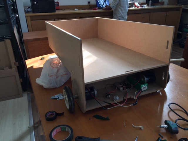
First Attempt :
This is a back view while fixingg the dc motors and checking the measurements to see if their is enough space.
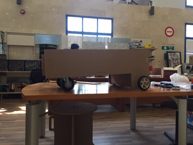
This is a side view showing my first design.
Final Attempt :
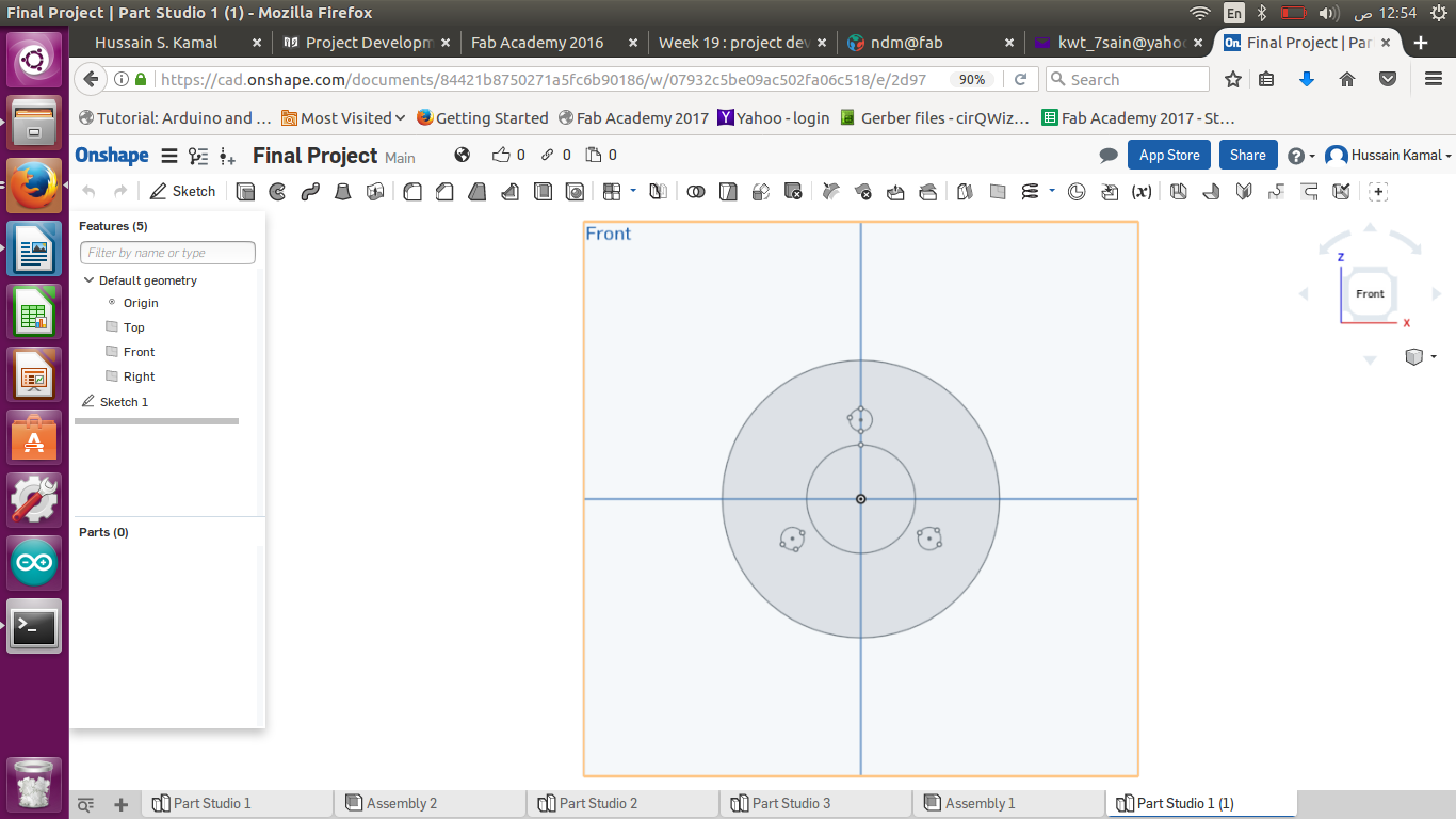
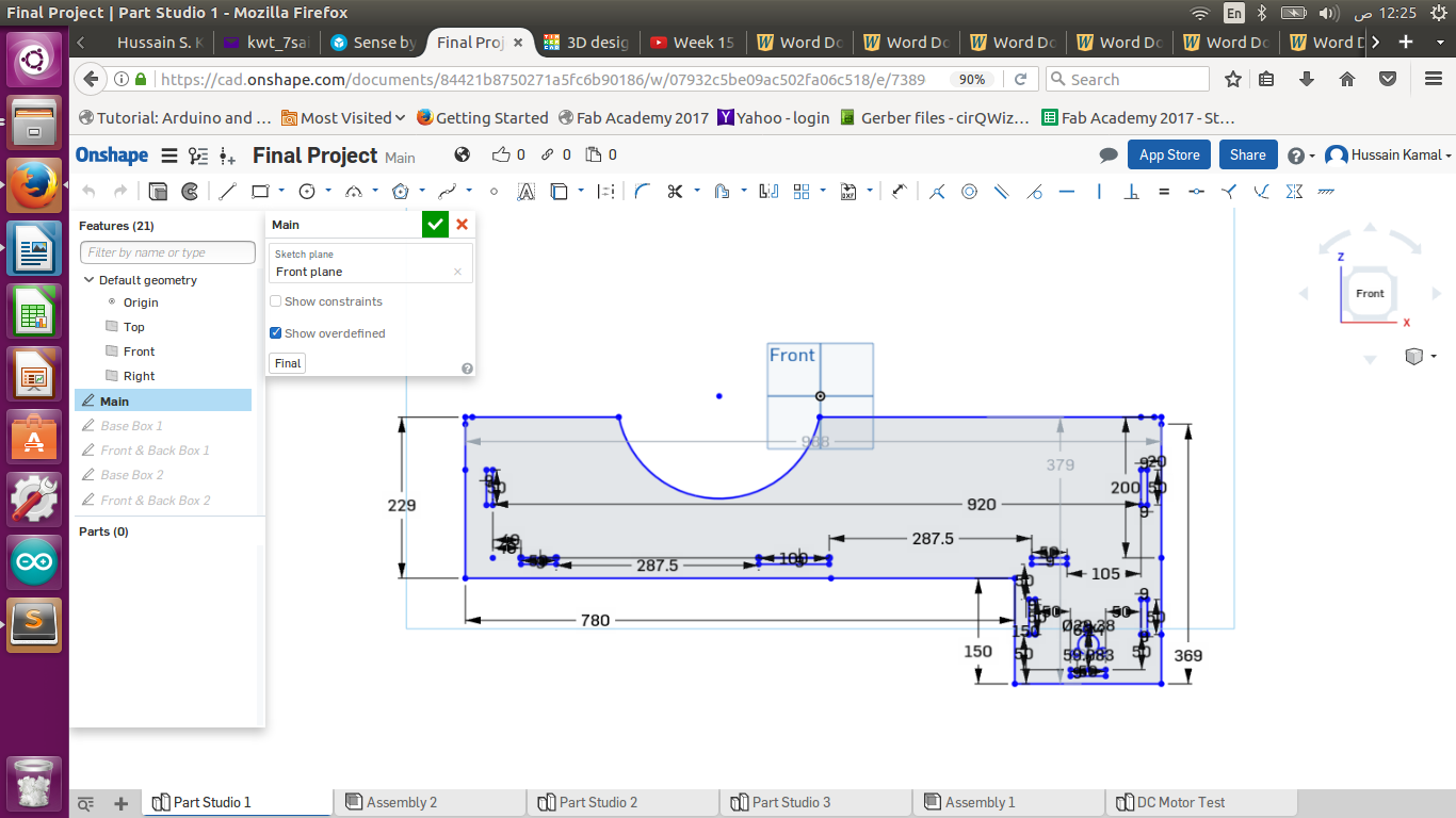
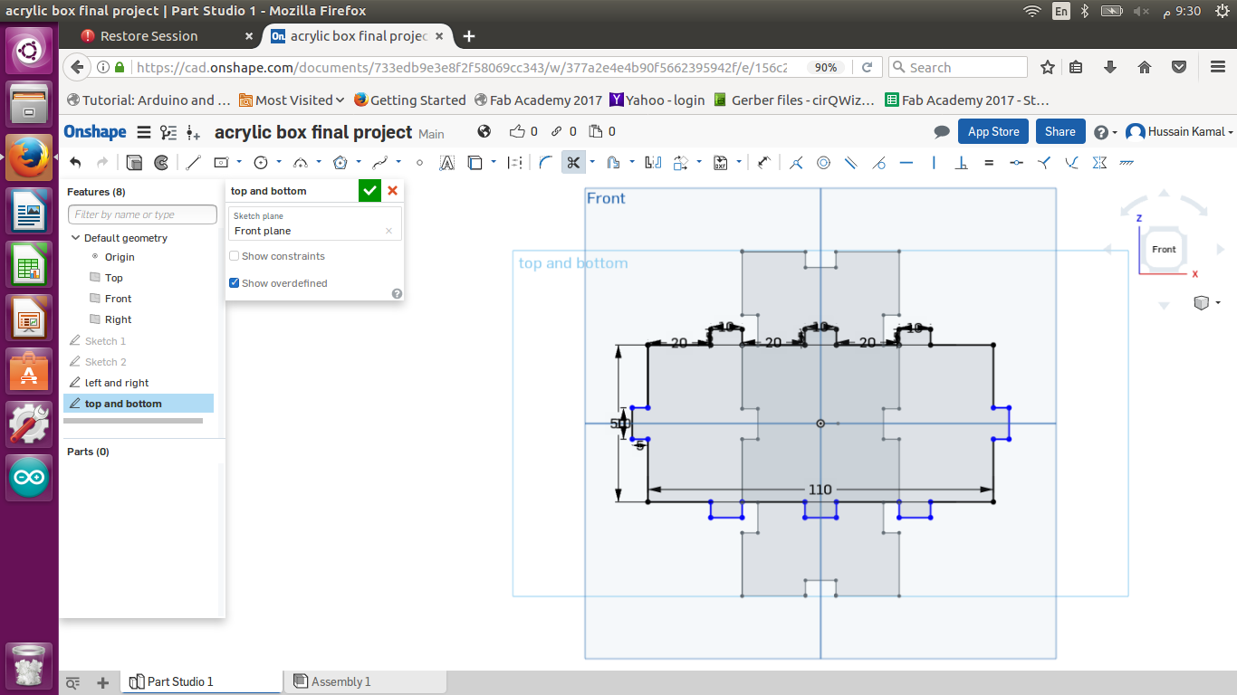
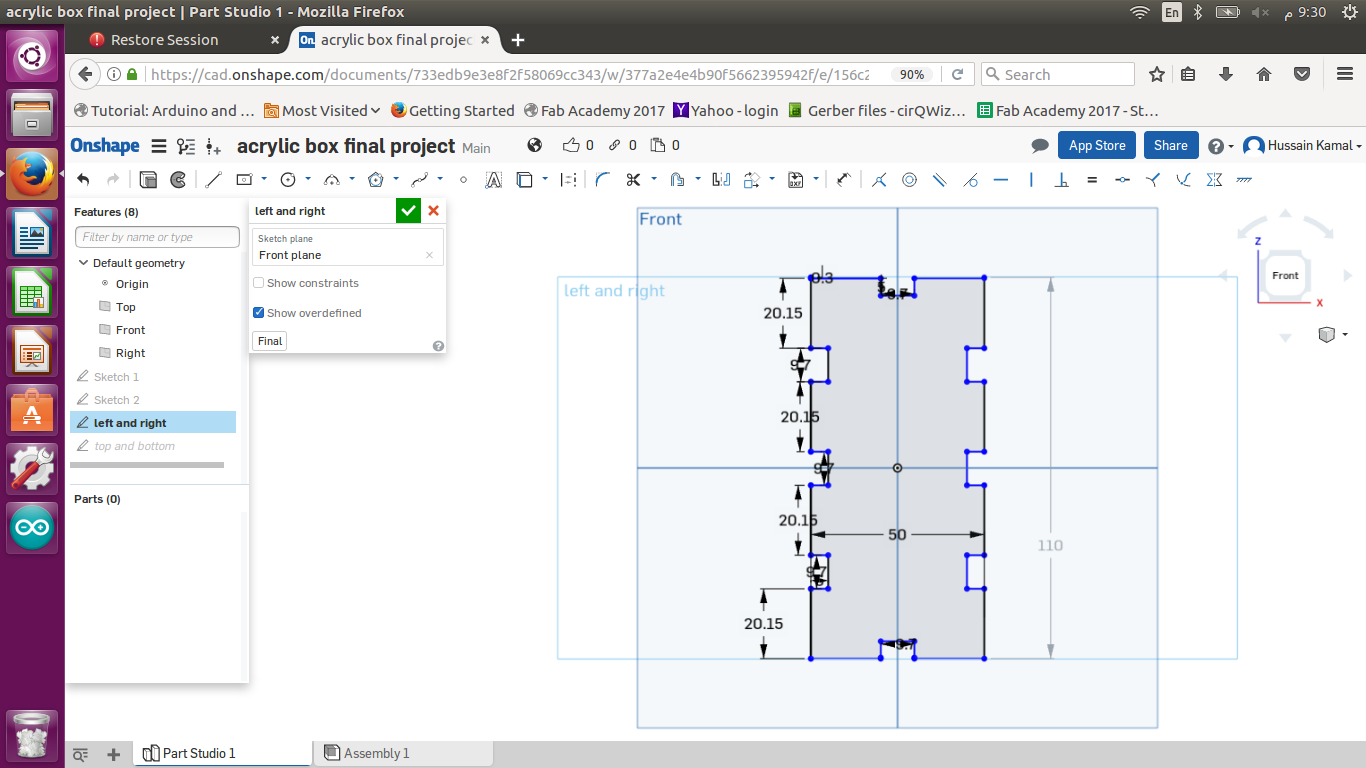
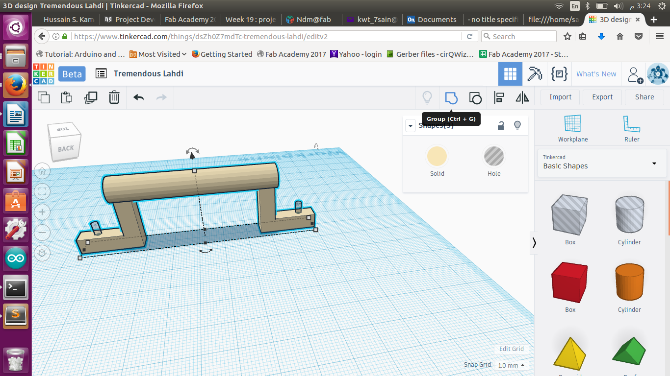
3D Design :
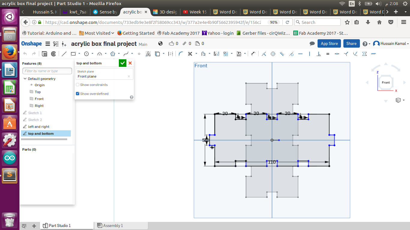
I only redesigned the side boards to cut again , while the inside boards dividing the cart into an upper basket and a lower box like shape for my electronics. I kept the sketch design exactly same as my first design but added a half circular cut as shown above.
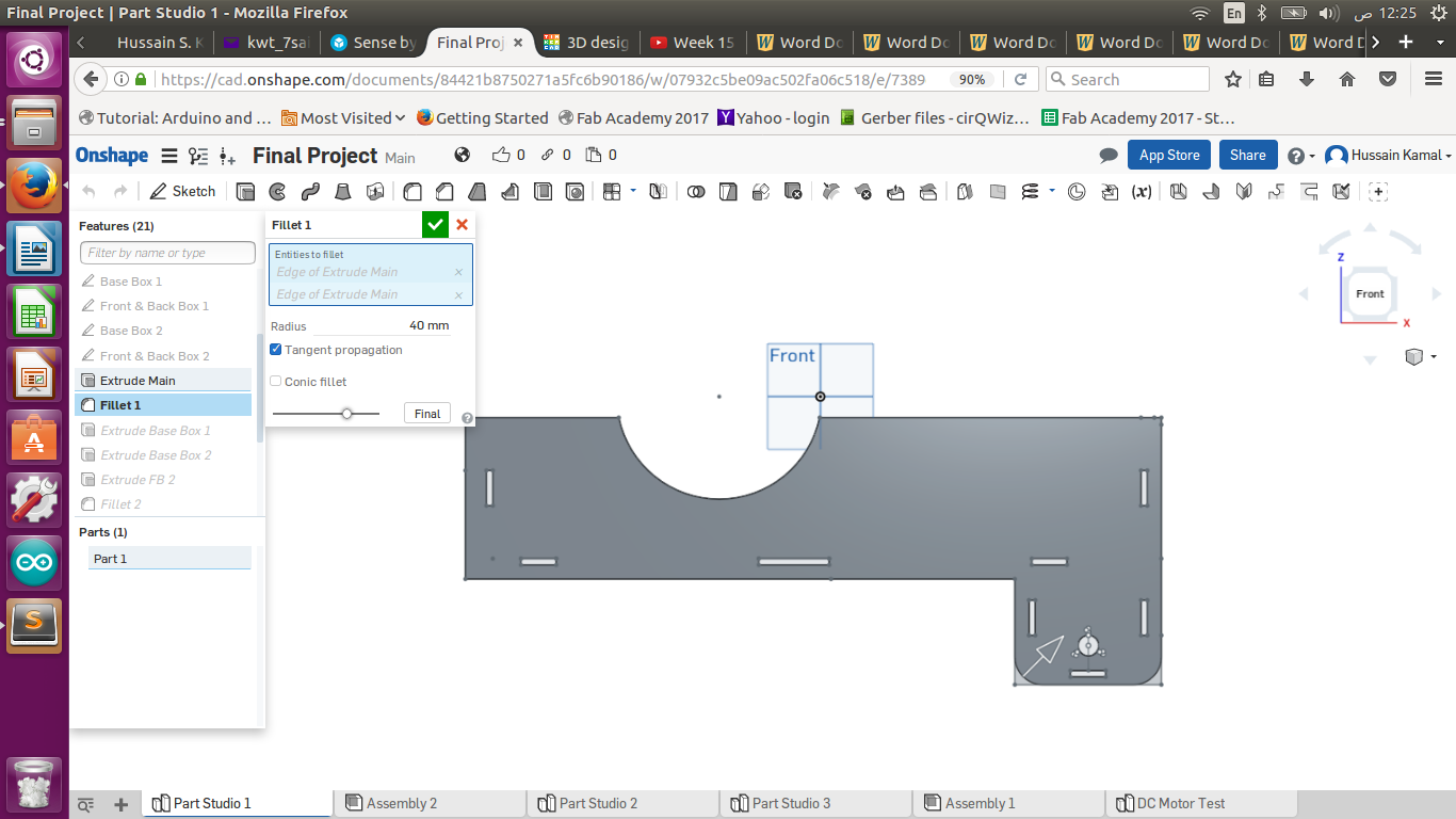
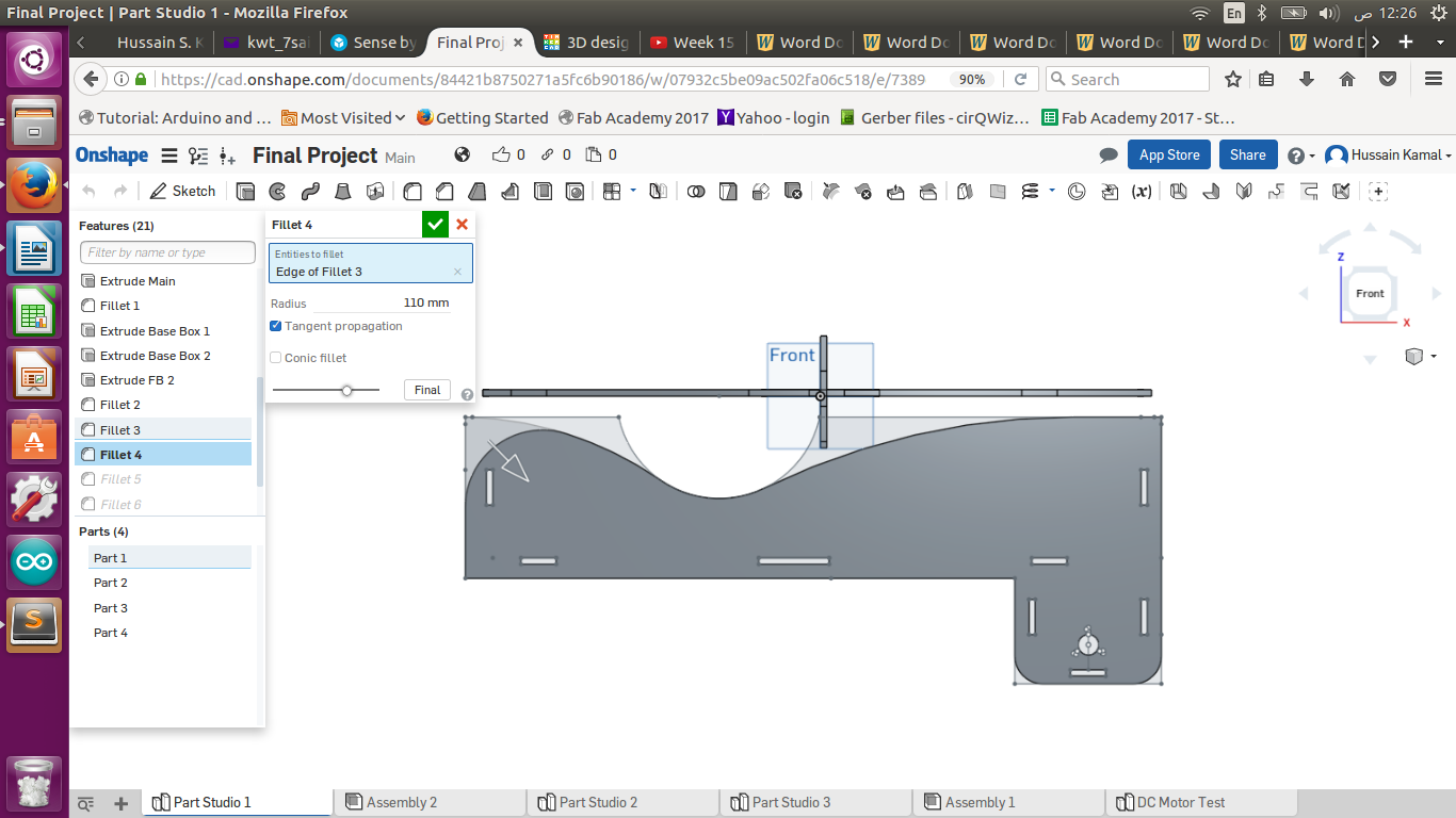
The I used the fillet feature to add curves on the below corner of my design next to the tires as shown and gave it 40 mm fillet on both corners down.
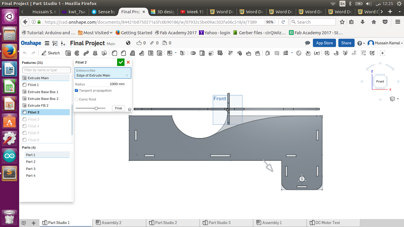
Then I gave a fillet also to on the top also where I made a half circular cut as shown above and gave it a 1000 mm fillet.
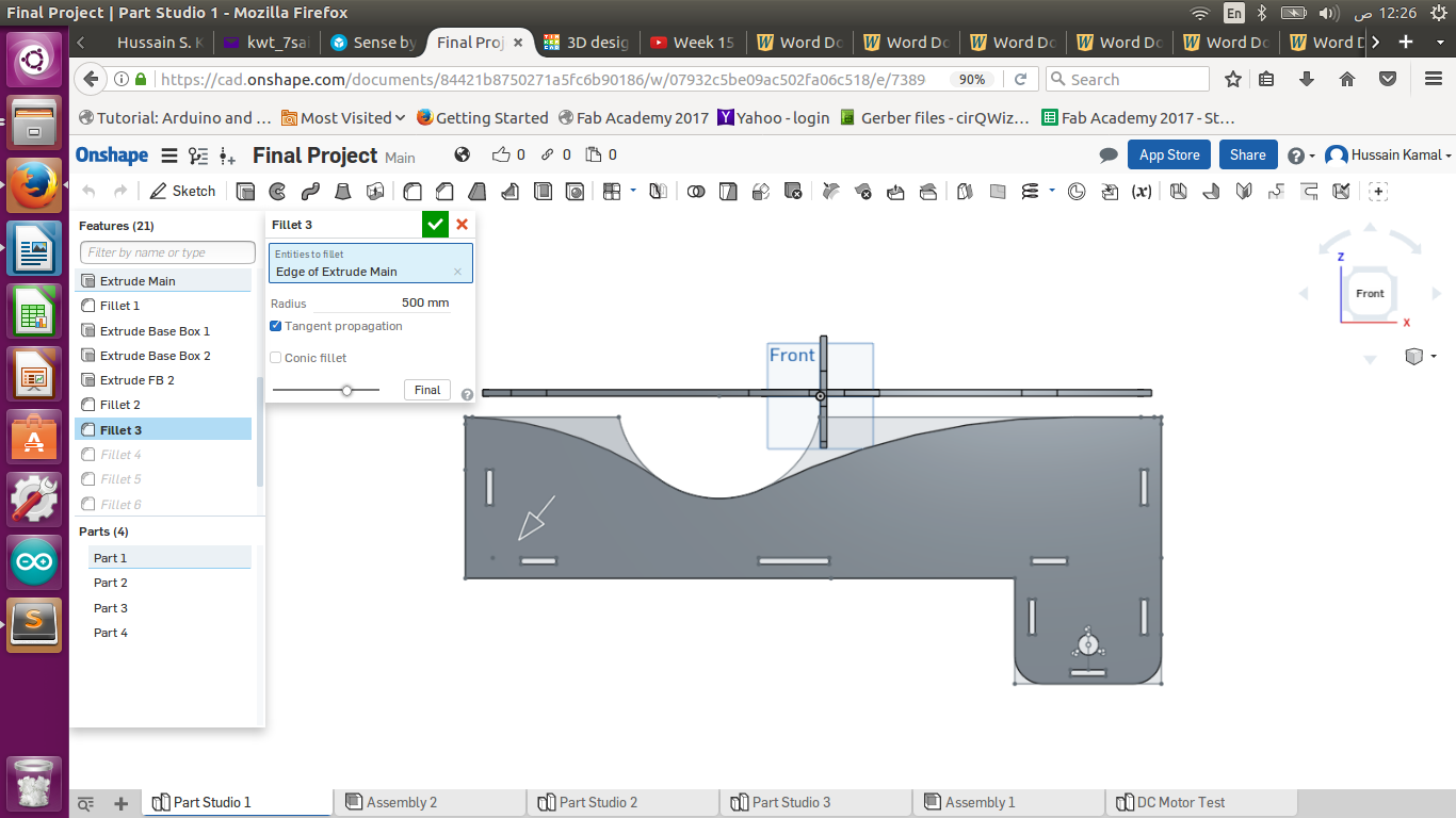
Then I gave a fillet curve for 500 mm on the opposite corner as shown above , the arrow tells which corner I'm using the fillet.
Then I used the fillet on the front corner of the wagon structure and gave it 110 mm , which was enough for a nice curved shape for the front.
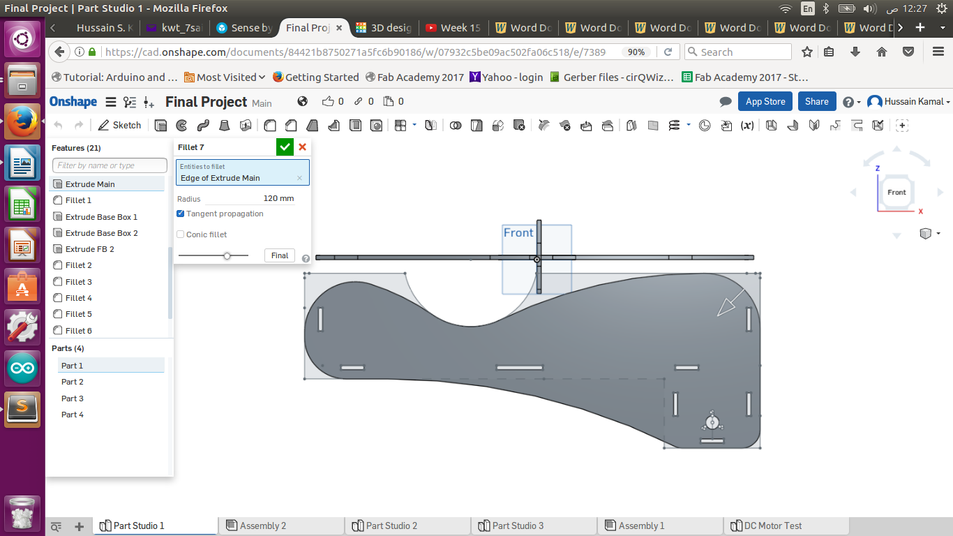
Then gave a 90 mm fillet on the front bottom as shown above with the arrow.
The I gave a 1400 mm fillet curve on the bottom and removed the sharp corner and made a nice curved design from the back tires below to the front.
Then I gave a 120 mm fillet for the top right as seen above with the arrow , And finally my design became smooth and without any sharp corners.
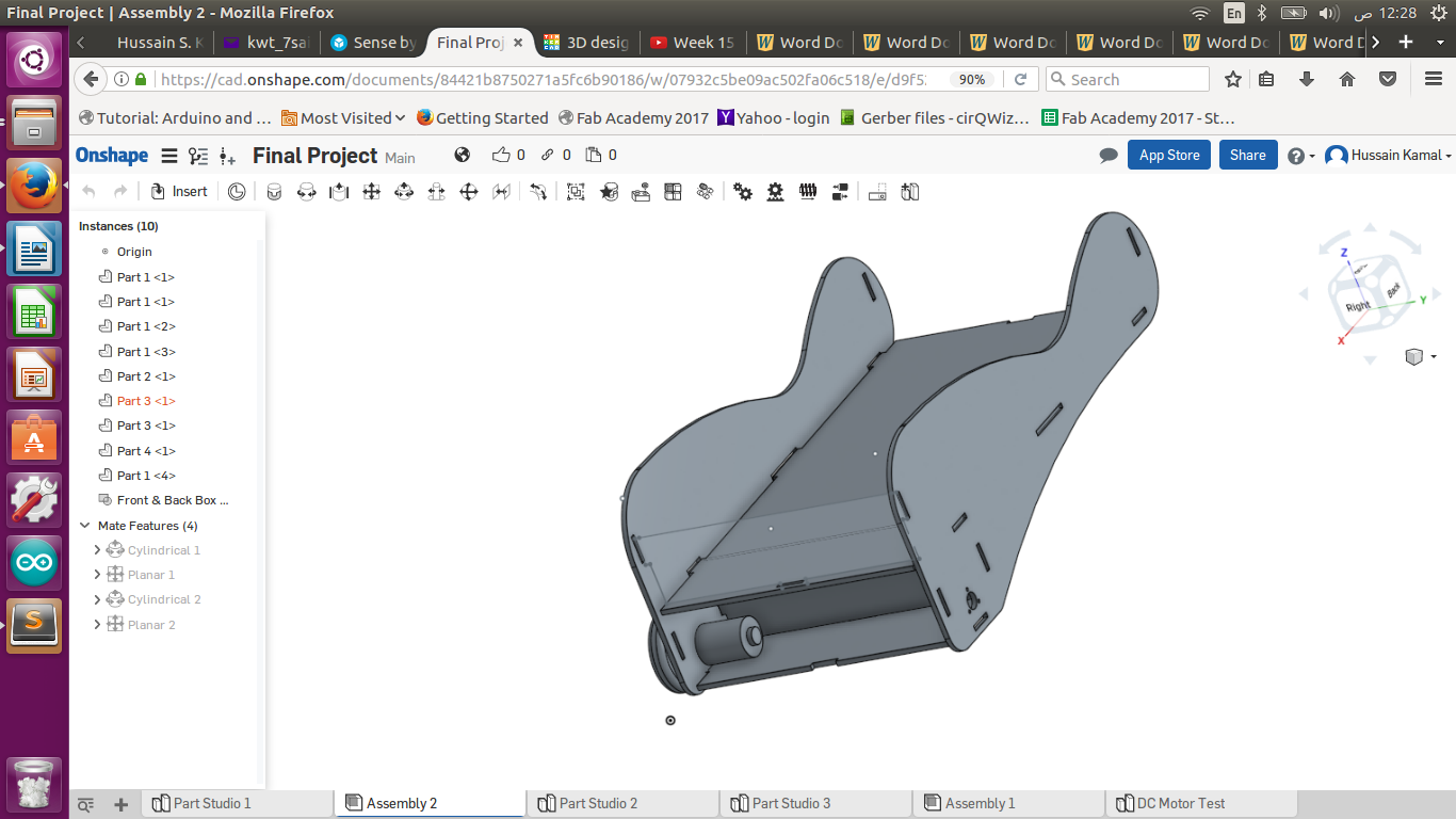
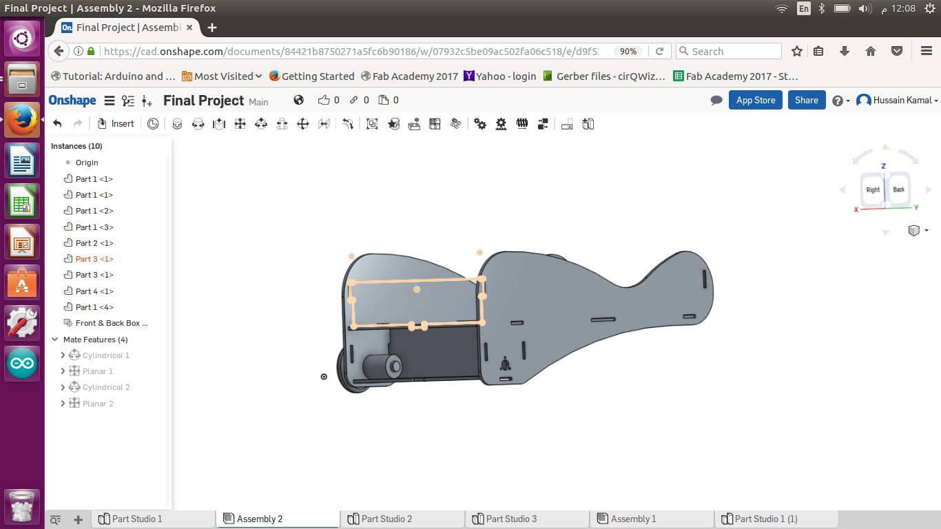
And this was after I assembled the demo tire and demo dc motor I designed exactly like the ones I had after measuring them , to see my measurements and fittings , and they seemed fine.
And the Back part of the upper basket seemed to fit good.
Then I used artcam software to generate the plt file for cutting my parts , above image shows my first design.
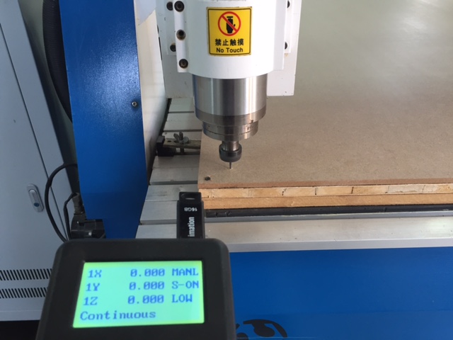
CNC Cutting :
And here I setted the home before I started the CNC machine cutting. I used a 9 mm wooden sheet.
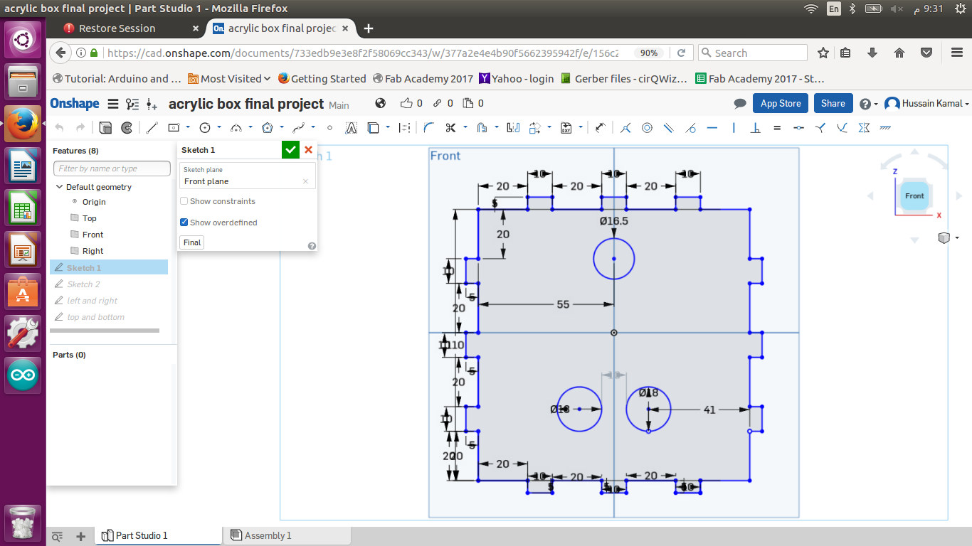
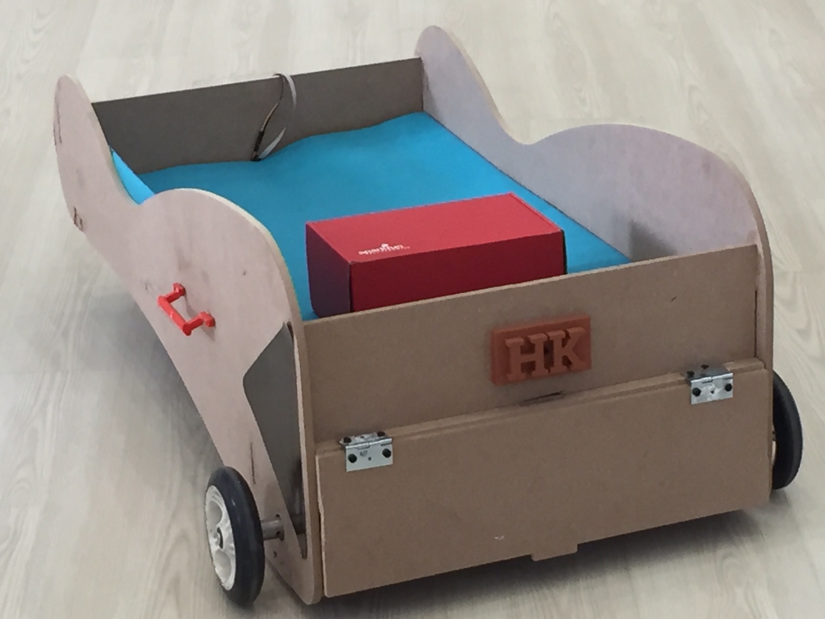
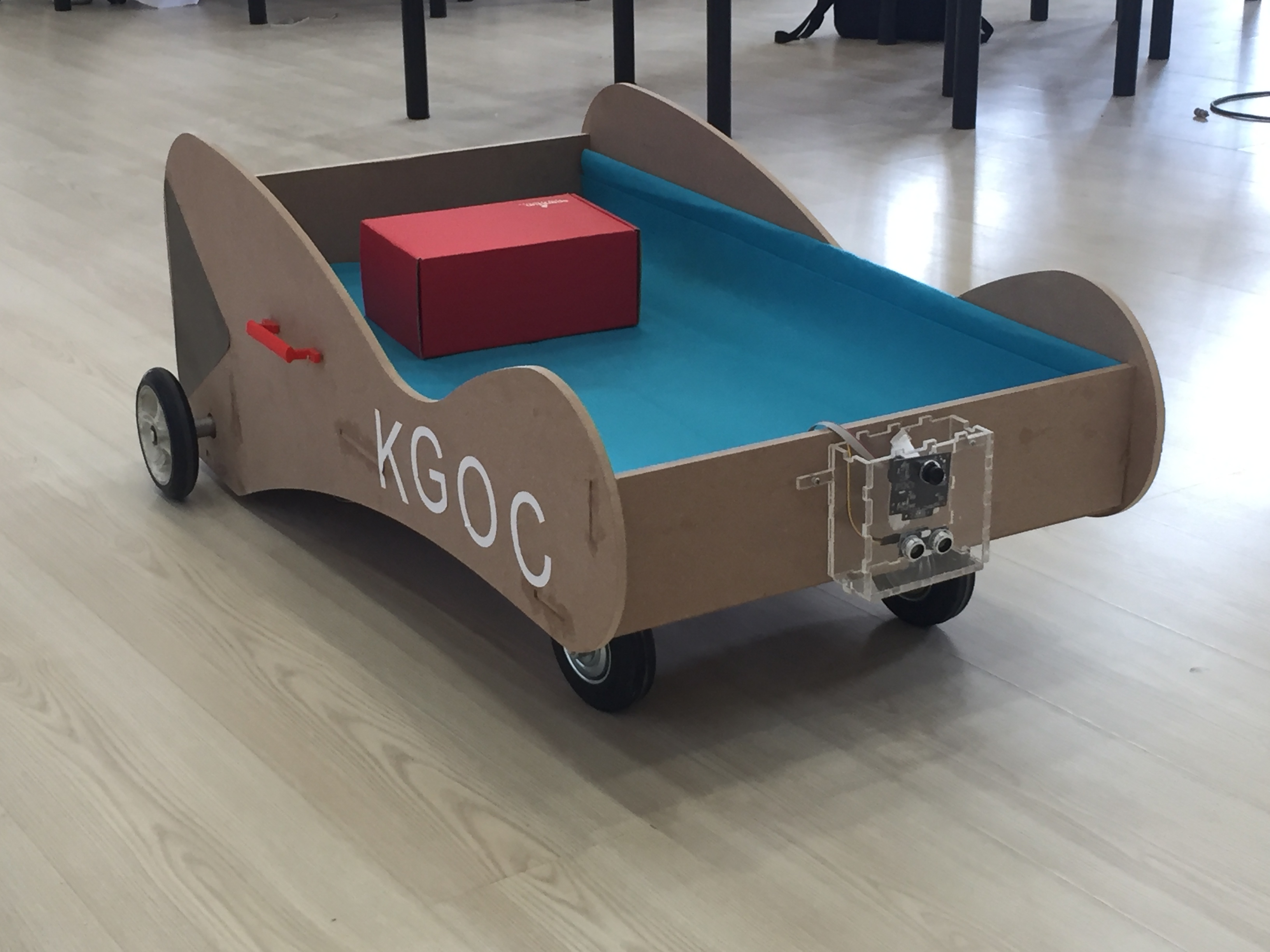
this is the front side of the box designed wone hole on the top for the pixi-cam which I measured 16.5 mm and two holes next to each other at the bottom 18 mm with a distance about 10mm between each other to match the ultra sonic sensor I'm gonna put their and the measurements were perfect in the first time.
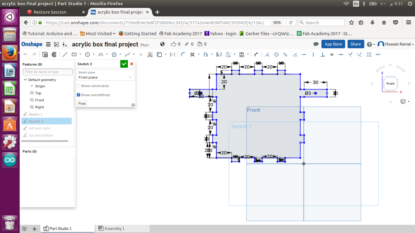
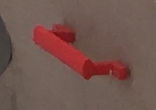
This is my initials HK , I made it about 90 mm since I had in mind for the logo to be around 100 mm.
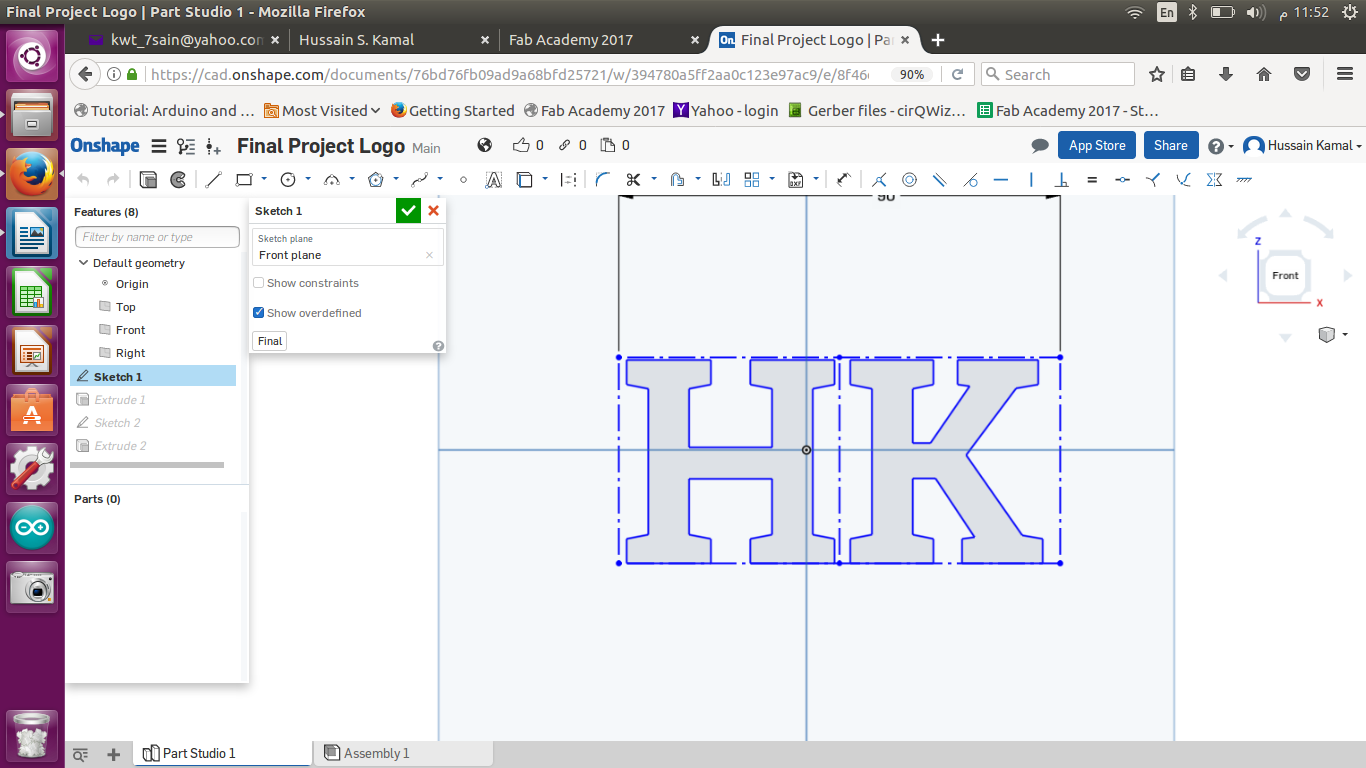
Them I created a rectangular box to be the base of my initials , also I added a screw hole to fix the screw and attach the hole 3D printed object to my wagon.
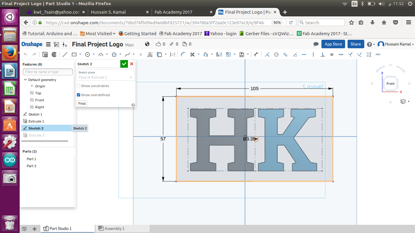
Then I extruded the two sketches the opposite way (10 mm each) and this was my final shape.
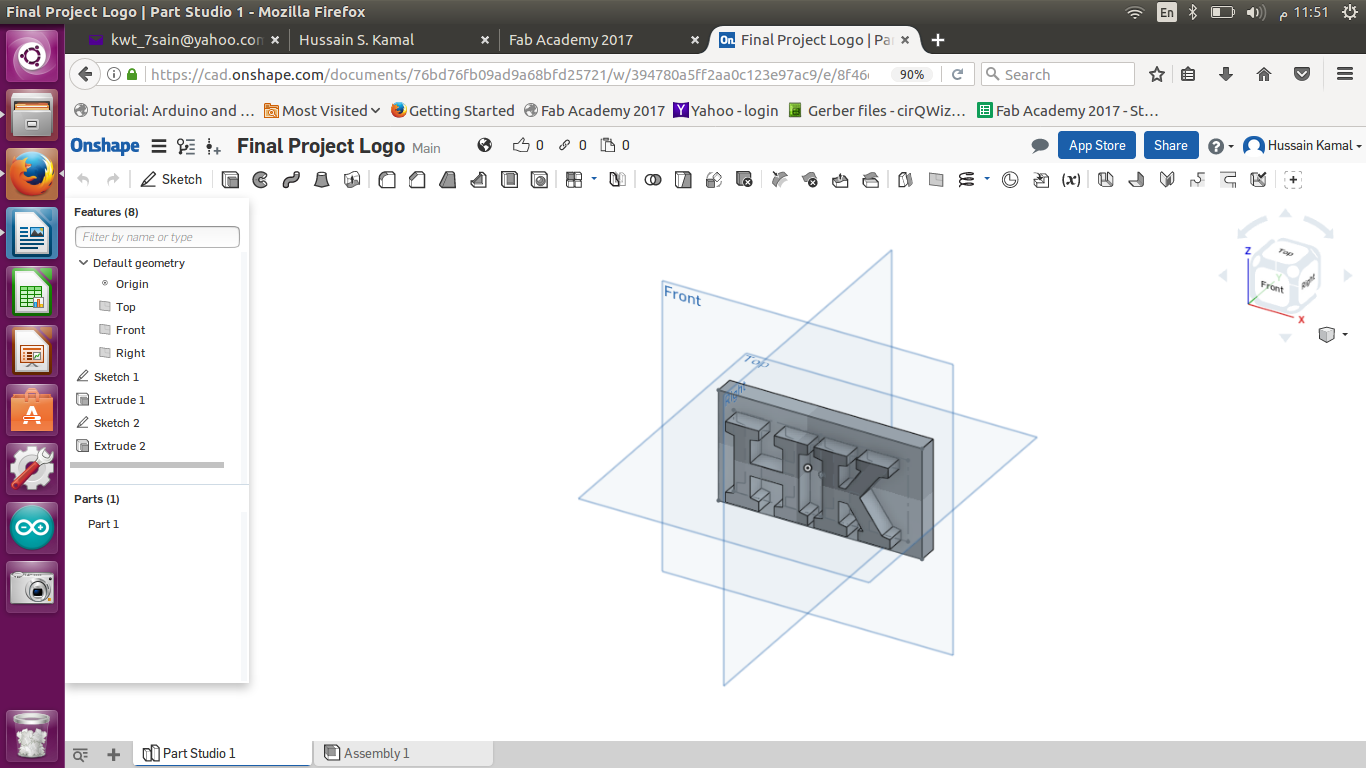
This was what I printed then which fitted exactly the way I wanted.
Vinyl Cutting :
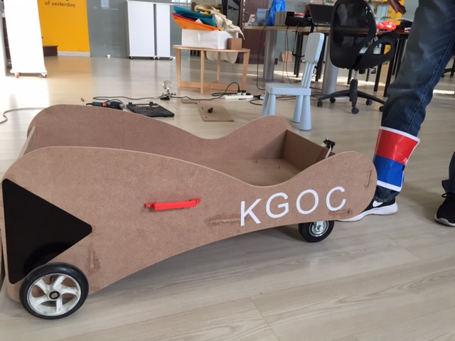
I designed a simple arrow to placed on each side of my wagon (right and left). Ans I also decided to vinyl cut of the logo of the company I work in KGOC to place it on the side of my wagon.
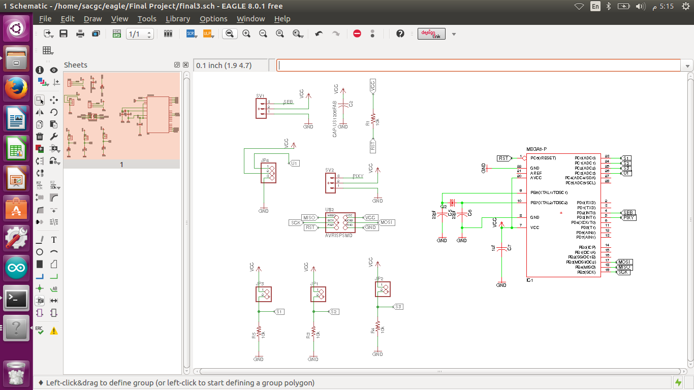
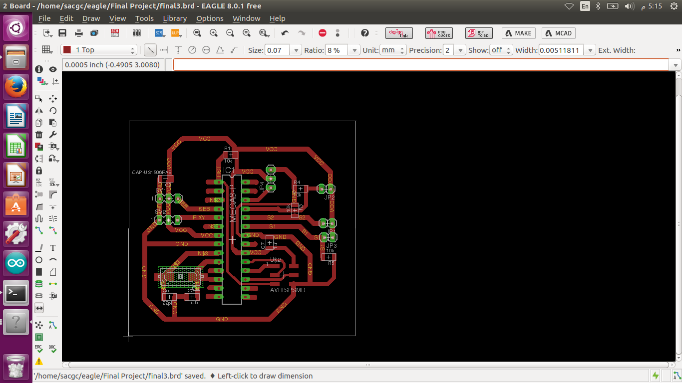
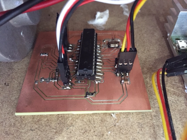
When I started designing my electronic board I decided to keep backup plans in-case the pixi-cam was not accurate , so I kept in mind using flex sensors to control my wagon , or a joystick , so I added 3 two pin heads for that issue , just as backup plans in-case the pixi-cam wasn’t accurate or didn’t work , but I was so happy and glad that the pixi-cam worked and was so accurate , so I did not solder the 3 two pin heads for the jostick/flex sensors because I didn’t need them anymore. It was actually really fun to play with after it worked.
This is a hero shot of my board after soldering , I had on short I managed to fix it thank god , I felt so relieved soldering the last electronic board in my life.
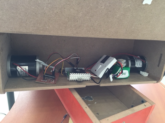
This is the view inside my back door electronic shelf before I sort it out and stick some of the parts in a neater way.
Programming :
First of all , I programmed my Pixi-cam using Pixy mon software. I defined two colors from a paper I printed containing red & blue. So when I open Pixy mon it opens the pixi-cam and I select by clicking and making a square on each color and define each one of the as a signature. Then it would recognize the paper I’m holding where ever I move it.
Then I added two libraries in arduino.
1- Pixi cam library to program the pixi-cam
2- Sabertooth library to program the DC motors
Pixi-cam code :
I had to program the pixi-cam to divide what it see's into 3 parts , so I could the define what to do in each part. So the total width of the cam is 480 , so the middle point is 240 , I took 30 pixels as a margin left and right from the middle point to define the middle part and the after the 30 pixels on each side of the middle part is the left and right parts.
Mistakes in coding :
Reaching the final code had many failures before it , like for example at first I kept the gap between the speed of the two dc motors 20 only and tried it , it just wont turn when I turn while walking because the speed was too fast for it to turn it did not have time , So I kept increasing the gap between the speed off the two dc motors that I defined for turning right and left many times until it was just perfect , I also made the speed of the dc motors while going forward to be a little slower so the turns and the way it functions would be clear for understanding and nice to follow around while walking slowly.
Pixi-cam :
Pixy pixy;
int xVal, yVal, widthVal, heightVal;
int xCenter, yCenter;
int mid = 240;
int centerMargin = 30;
int detected = 0;
int detectedp = 0;
int averageCount = 0;
int LeftRightRange = 300;
int countBuzzer = 0 ;
//
int countCurrent = 0;
int sumCurrent=0;
float avgCurrentVal =0;
int currentVal =0;
int limitBuzzer1=20 ;
int limitBuzzer2 =150 ;
void setup()
{
Serial.begin(9600);
Serial.print("Starting...\n");
pinMode(8,OUTPUT);
pixy.init();
SWSerial.begin(9600);
ST.autobaud();
}
void loop()
{
digitalWrite(8,1);
static int i = 0;
int j;
uint16_t blocks;
char buf[32];
// grab blocks!
blocks = pixy.getBlocks();
// If there are detect blocks, print them!
if (blocks)
{
i++;
detected = 1;
// do this (print) every 50 frames because printing every
// frame would bog down the Arduino
//if (i%50==0)
// {
//sprintf(buf, "Detected %d:\n", blocks);
//Serial.print(buf);
for (j=0; j<blocks; j++)
{
// sprintf(buf, " block %d: ", j);
// Serial.print(buf);
// pixy.blocks[j].print();
xVal = pixy.blocks[j].x;
yVal = pixy.blocks[j].y;
widthVal = pixy.blocks[j].width;
heightVal = pixy.blocks[j].height;
xCenter = xVal + (widthVal / 2);
yCenter = yVal + (heightVal / 2);
//Serial.print(xCenter);
//Serial.println(" ");
//Serial.println(yCenter);
Ultrasonic Sensor :
Then I programmed the Ultrasonic sensor to stop the DC motors when I’m 200 mm in-front of my wagon so it wouldn’t crash into me.
Below is the code for the ultrasonic sensor :
int sensorValue = analogRead(A3);
if( sensorValue<200)
{
ST.motor(1, 30);
ST.motor(2, 30);
delay(100);
ST.motor(1, 0);
ST.motor(2, 0);
}
else if( sensorValue>200)
DC Motors :
Then I programmed the DC motors and defined the three parts of the pixi-cam code I mentioned above. I programmed the DC motors so that if the object is in the middle part of the pixi-cam it would turn on both DC motors the same speed so that it would follow me straight. And if the object is in the left part of the pixi-cam the speed of the left dc motor (ST.motor(1 …) would be -30 and the right dc motor (ST.motor(2 …) would be 30. The more the gap is between the speeds of the left and right dc motors , the sharper the turn of the wagon will be. And last if the object is at the right part of the pixi-cam the speed of the left dc motor would be 30 and the rght dc motor would be -30 in order to turn right , until the object becomes in the middle part of the view of the pixi-cam, then it both dc motors would be on the same speed to go straight forward, and by this it would follow me.
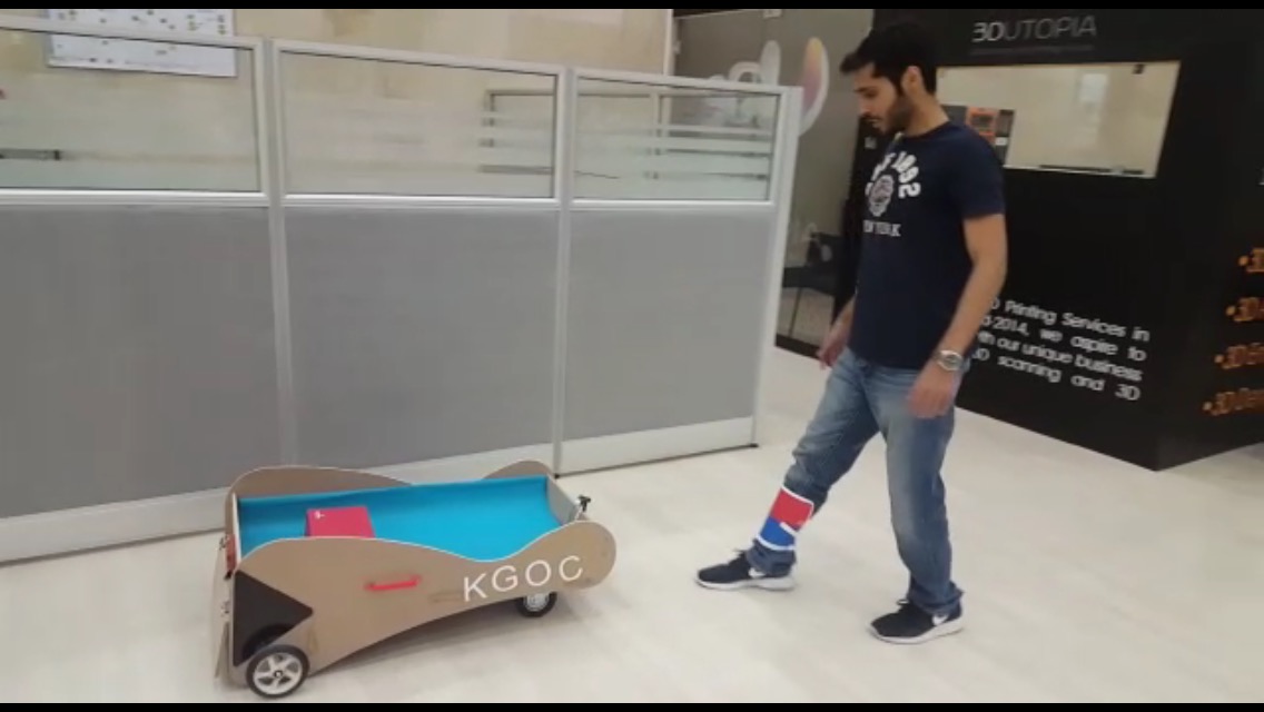
The result of my final project was outstanding and great , it was really fun to walk around and have something follow you , I’m really beginning to think considering it as a toy. I feel that this is a great achievement and I’m so proud of what I have achieved in such short period of time.
I was testing the turns which were pretty accurate and nice.