Week 15
Networking and communication
In this week,The task is to make a wired or wireless network using multiple processors.
In electronics,inter linking of circuits (processors or Other Integrated Circuits) are carried out to communicate or transfer data.for those individual circuits to swap their information, they must share a common communication protocol.
Serial and Parallel
Communication:
Data can be transmitted between a sender and a receiver in two main ways: serial and parallel.
Serial communication is the method of transferring one bit at a time through a medium.
![]()
Parallel communication is the method of transferring blocks, eg: BYTEs, of data at the same time.
Synchronous vs
Asynchronous:Synchronous data transfer: sender and receiver use the same clock
signal.both the sender and receiver access the data according to the same
clock. Therefore, a special line for the clock signal is required. A master (or
one of the senders) should provide the clock signal to all the receivers in the
synchronous data transfer.Asynchronous data transfer: sender provides a
synchronization signal to the receiver before starting the transfer of each
message.there is no common clock signal between the sender and receivers.
Examples of synchronous
data transfer: Inter IC bus (I2C),Serial Peripheral Interface (SPI),
I2C and SPI
The I2C (Inter-IC)
protocol is used with the I2C bus introduced by Phillips 20 years ago.It is
still used for embedded applications.It operates in half duplex data transfer
format.Half duplex means that data on the same wire goes different directions
at different times. The I2C protocol is simple and can be implemented on simple
and small microprocessors using software or hardware.
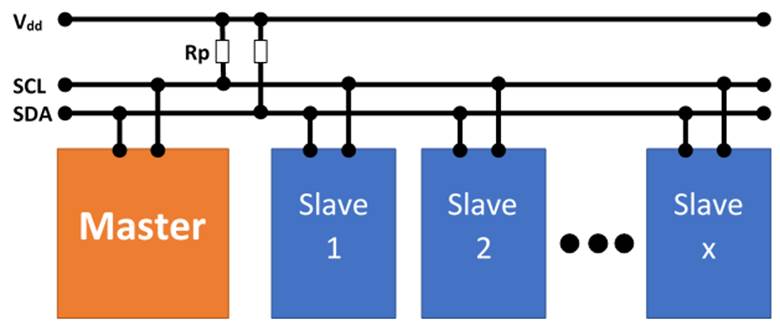
I2C uses two lines, one
for synchronization clock (SCL) and one for data and acknowledgement (SDA).The
BUS MASTER is the chip issuing the commands on the BUS. The IC that initiates a
data transfer on the bus is considered the BUS MASTER and all the others are
regarded as the bus slaves.I2C bus transfers consist of a number of bytes
framed by a start condition and a stop condition. Once the transfer is
initiated, eight data bits are sent.In the ninth clock cycle, the receiver
indicates the success of the data transfer by raising SDA high; otherwise, SDA
is low.Multiple bytes can be sent by repeating this 9-clock cycle.
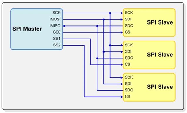
The SPI (Serial
Peripheral Interface) can be either half duplex or full duplex. It can transfer
as fast as 2.5 Mbits per second. SPI control is more complex and is usually
implemented in hardware.SPI has three signals:
1-clock,
2-slave-in-master-out,
3-slave-out-master-in.
SPI data transfer follows the
rising edge or falling edge of the clock.The user can select the edge of the
clock to be used for data transfer. SPI supports the transfer of different word
lengths.
The most obvious drawback of SPI is the number of pins required. Connecting a single master to a single slave with an SPI bus requires four lines; each additional slave requires one additional chip select I/O pin on the master. The rapid proliferation of pin connections makes it undesirable in situations where lots of devices must be slaved to one master. Also, the large number of connections for each device can make routing signals more difficult in tight PCB layout situations. SPI only allows one master on the bus, but it does support an arbitrary number of slaves (subject only to the drive capability of the devices connected to the bus and the number of chip select pins available).SPI supports different word lengths.
Word length can be from 1 to 8
bits per word.Both master and slave should use the same
1-clock edge and
2-data length.
Although the SPI is usually
implemented in hardware, it can be implemented with software and several
parallel I/O ports.
Referred Websites:Sparkfun
Master and slave
boards
I choosed i2C model communication for this week assignment. One master board and two slave boards.For master board,i referred fabacademy resource here. For the slave board,I choosed this board. For two slave boards,I changed the LED colors only. Blue and white.
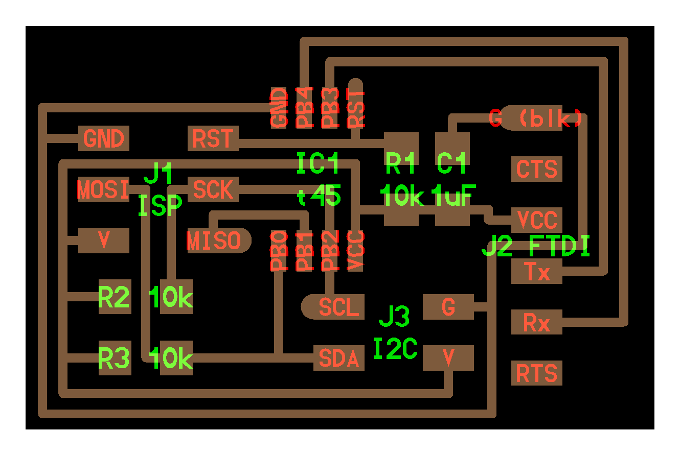
Master Board
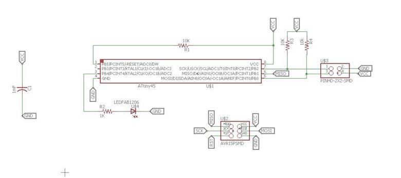
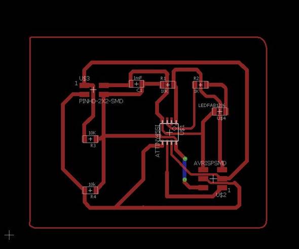
I drew the schematic and created corresponding Board file in eagle
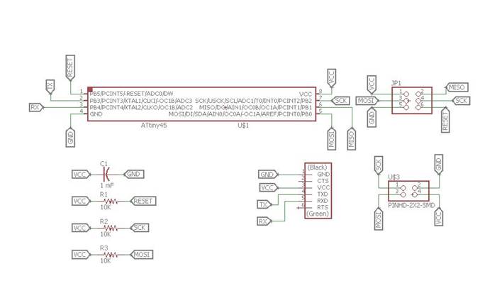
Eagle Schematic
Eagle board file.
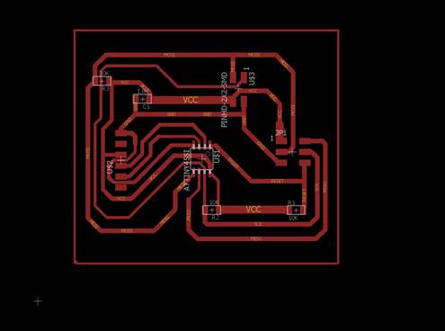
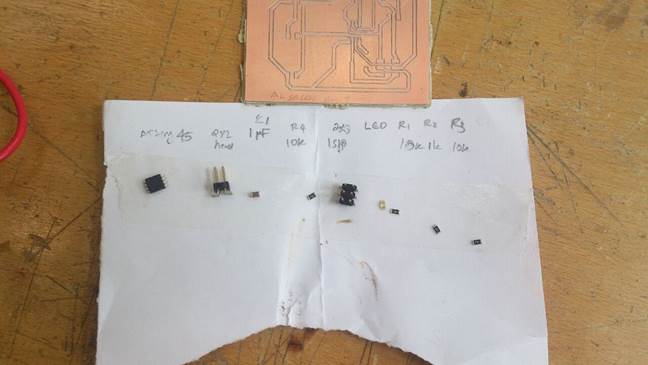
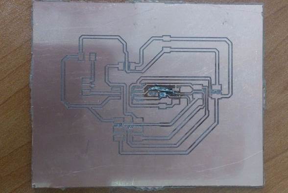
I created corresponding .cmp file for pcb milling machine.
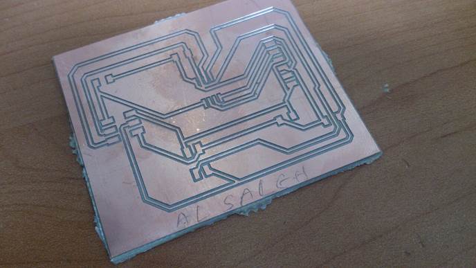
Some of the adjacent traces were not separated. So i seperated by using the precision knife.
Then i soldered the components in their respective positions and verified that there is no contacts between adjacent traces.
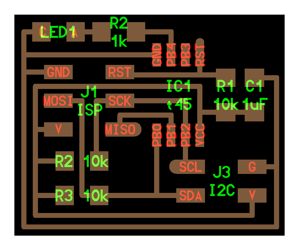
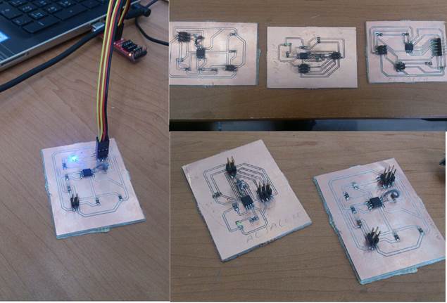
Slave boards
For slave boards i drew the schematic and generated corresponding board file.bot the slaves are with LED.Blue and other with white LED.designed in eagle with inserting corresponding components.
Slave Schematic
Slave board
Soldering of components on the board with respective places are done.
You can see there is a variation between the board file i designed and the above board. This board was having the problem with traces. So i changed the board design and added via. So that is the design i shown in board design. I connected a jumper wire between that points.
Burning bootloader and testing the boards.
After soldering the components. I burned the bootloader and tested sample program to blink LED using ISP programmer.
Codes
1- For master
#include < TinyWireM.h>
void setup()
{
TinyWireM.begin(); // join i2c bus (address optional for master)
}
byte x = 0;
byte x1 = 0;
void loop() {
TinyWireM.beginTransmission(0x4);
TinyWireM.write(++x % 2);
TinyWireM.endTransmission();
delay(1000);
TinyWireM.beginTransmission(0x3);
TinyWireM.write(++x1 % 2);
TinyWireM.endTransmission();
delay(1000);
}
2- For slave 1
#define output(directions, pin)
(directions |= (1 << pin)) // set port direction for output
#define input(directions, pin) (directions
&= (~(1 << pin))) // set port direction for input
#define set(port, pin) (port |=
(1 << pin)) // set port pin
#define clear(port, pin) (port
&= (~(1 << pin))) // clear port pin
#define LED_PIN PB4
#define I2C_SLAVE_ADDRESS 0x1 //
Address of the slave 2
#include <TinyWireS.h>
void setup()
{
output(DDRB,
LED_PIN);
clear(PORTB,
LED_PIN);
TinyWireS.begin(I2C_SLAVE_ADDRESS);
// join i2c network
}
void loop()
{
byte recd = 1;
if(TinyWireS.available()) {
recd =
TinyWireS.receive();
if(recd == 1) {
clear(PORTB,
LED_PIN);
} else {
set(PORTB,
LED_PIN);
}
}
}
3-For slave2
#define output(directions, pin)
(directions |= (1 << pin)) // set port direction for output
#define input(directions, pin)
(directions &= (~(1 << pin))) // set port direction for input
#define set(port, pin) (port |=
(1 << pin)) // set port pin
#define clear(port, pin) (port
&= (~(1 << pin))) // clear port pin
#define LED_PIN PB4
#define I2C_SLAVE_ADDRESS 0x2 //
Address of the slave 1
#include <TinyWireS.h>
void setup()
{
output(DDRB,
LED_PIN);
clear(PORTB,
LED_PIN);
TinyWireS.begin(I2C_SLAVE_ADDRESS);
// join i2c network
}
void loop()
{
byte recd = 1;
if(TinyWireS.available()) {
recd =
TinyWireS.receive();
if(recd == 1) {
clear(PORTB, LED_PIN);
} else {
set(PORTB,
LED_PIN);
}
}
}
TinyWireM.h and TinyWireS.h are the library for master and slaves respectively.Address are defined as 0x1 and 0x2 respectively.
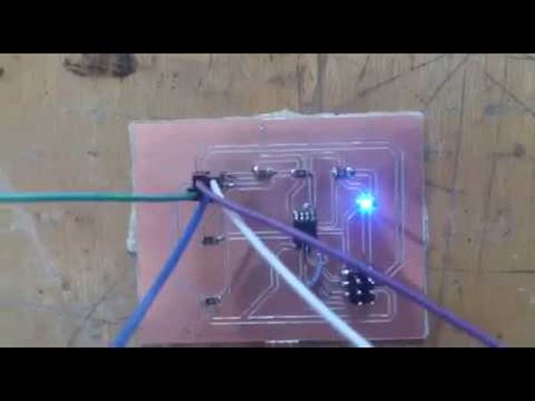
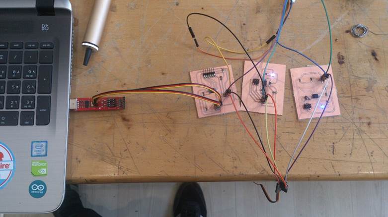
Connection and Output
I connected each VCC,GND,SCL and SDA pins of master and slaves. After that i powered the master board using the ISP programmer. I got the output as well.
Files
Master board Eagle Schematic: Master Schematic
Master board Eagle Board : Master Board file
Master board Machinefile(.cmp): master board machine file
Slave board Eagle schematic:Slave schematic
Slave board Eagle Board:Slave board file
Slave board Machine file(.cmp):Slave board Machine file
Output video: