First, the PCB sketch was was copied to the system connected to the PCB miller. The circuit is downloadable from http://fab.cba.mit.edu/classes/863.16/doc/projects/ftsmin/index.html - (a copy of which was with the instructor). Used Roland MODELA 3D plotter MDX-20 for printing the PCB on a paper-epoxy bare board.
(1) The instructor removed and refixed a new sheet called "sacrificial bed" on top of the metal surface underneath the milling head.
(2) The existing print head was removed using an allenkey meant to unscrew it. Then using a 1/64 bit, the circuit was constructed by etching out the copper layers appropriately. Then using a 1/32 bit, the PCB was cut out resembling a USB pen drive.
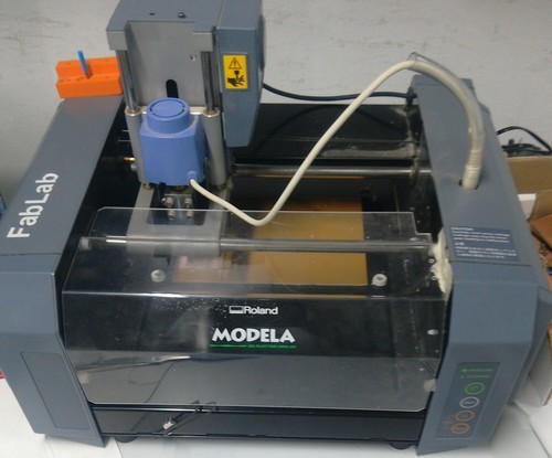 The plotter |
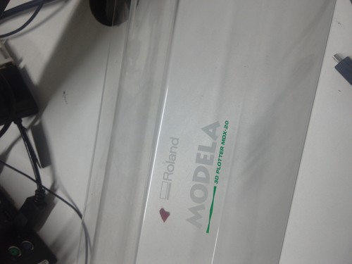 Plotter name |
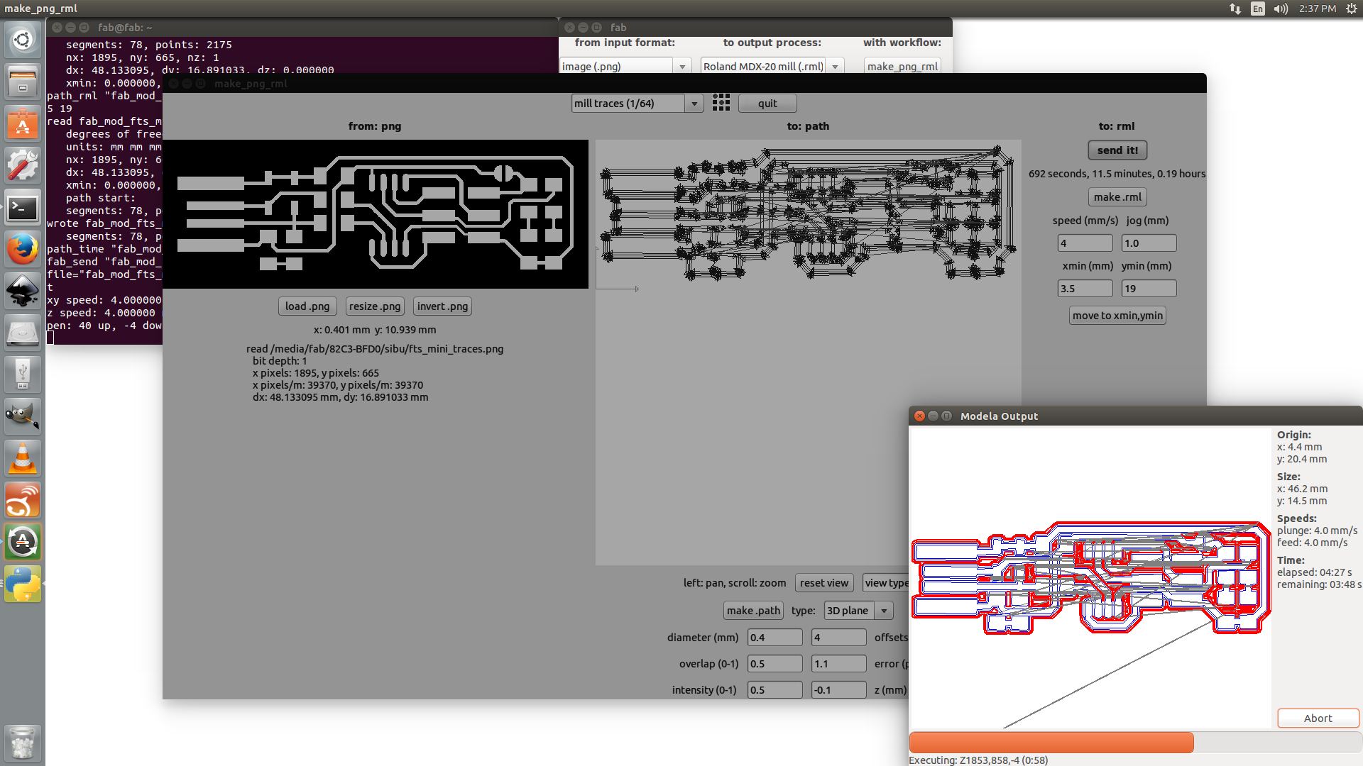 Settings |
PCB milling Video |
The PCB drawing(Courtesy FabAcademy)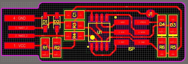 |
(3)There were 9 different components to be soldered on to the PCB. For me identifying them once removed from the bin was difficult. Hence, I cut out a sheet of cardboard of 3x3 round slots from the waste cardboards. Actually it was the base sheet of the laser cutting assignment by another fellow. On the base of each slot I wrote numbers from 1 to 9, and kept a sheet of the components again numbered from 1 to 9.
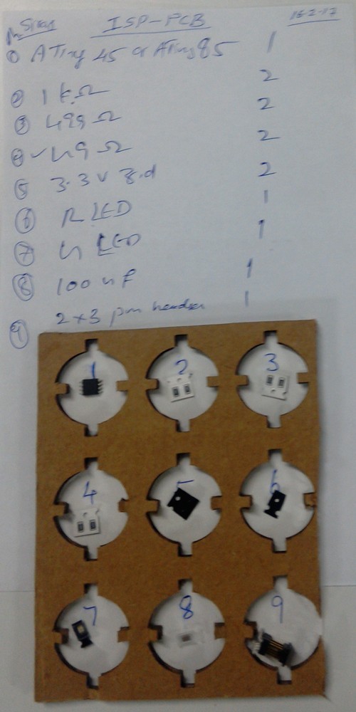 Components |
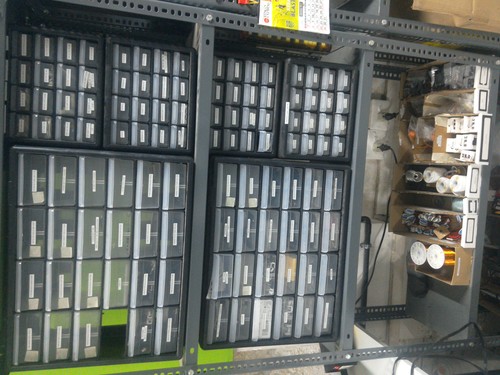 Inventory |
(3) The soldering of these tiny components was a tedious task for this old man, but it was me who completed first here at my centre! One component I wrongly soldered was helped by the instructor and got resoldered.
The Schematic(Courtesy FabAcademy) 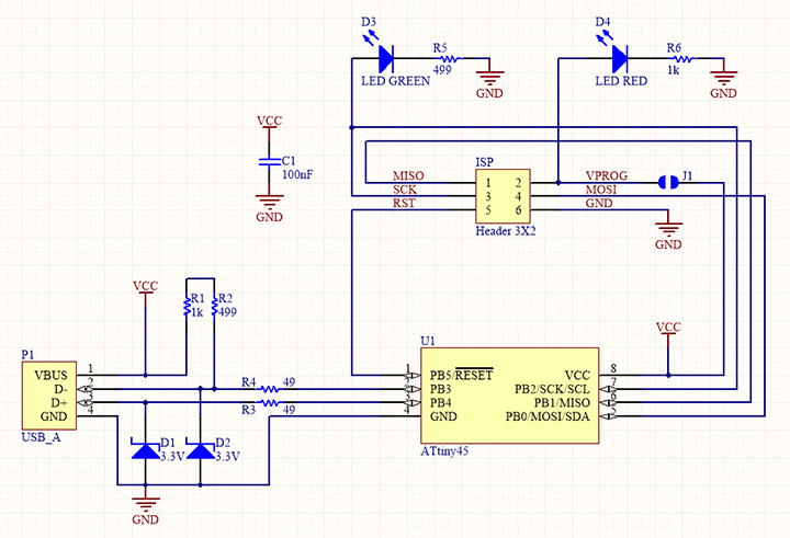 |
|
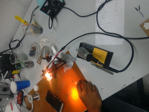 Soldering station |
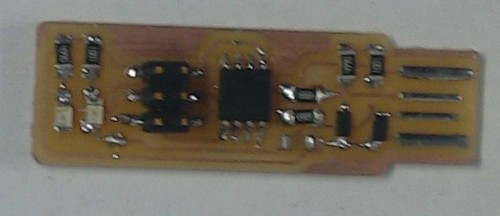 The Circuit |
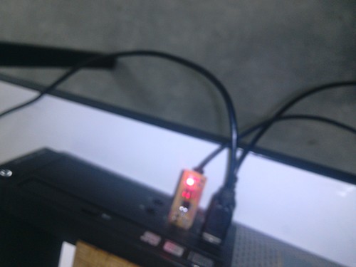
(4) Connected to the PC the LED was glowing! dmesg command reported sensing of something in the USB port!
 |
(1) Before connecting [fab@ask ~]$ dmesg .......... [38727.941787] scsi host7: usb-storage 1-1.4:1.0 [38728.967041] scsi 7:0:0:0: CD-ROM Linux File-CD Gadget 0310 PQ: 0 ANSI: 2 [38728.969100] sr 7:0:0:0: [sr1] scsi-1 drive [38728.969208] sr 7:0:0:0: Attached scsi CD-ROM sr1 [39801.827813] usb 1-1.4: USB disconnect, device number 23 |
| (2) After connecting the USB circuit [fab@ask ~]$ dmesg .......... 38728.969208] sr 7:0:0:0: Attached scsi CD-ROM sr1 [39801.827813] usb 1-1.4: USB disconnect, device number 23 [41377.223635] usb 1-1.5: new low-speed USB device number 24 using ehci-pci [41377.296991] usb 1-1.5: device descriptor read/64, error -32 [41377.477005] usb 1-1.5: device descriptor read/64, error -32 [41377.656975] usb 1-1.5: new low-speed USB device number 25 using ehci-pci [41377.730291] usb 1-1.5: device descriptor read/64, error -32 [41377.910345] usb 1-1.5: device descriptor read/64, error -32 [41378.090262] usb 1-1.5: new low-speed USB device number 26 using ehci-pci [41378.503638] usb 1-1.5: device not accepting address 26, error -32 [41378.576962] usb 1-1.5: new low-speed USB device number 27 using ehci-pci [41378.990292] usb 1-1.5: device not accepting address 27, error -32 [41378.990421] usb 1-1-port5: unable to enumerate USB device |
[fab@ask ~]$ lsusb Bus 002 Device 002: ID 8087:8000 Intel Corp. Bus 002 Device 001: ID 1d6b:0002 Linux Foundation 2.0 root hub Bus 001 Device 018: ID 046d:c077 Logitech, Inc. M105 Optical Mouse Bus 001 Device 029: ID 1781:0c9f Multiple Vendors USBtiny Bus 001 Device 003: ID 413c:2107 Dell Computer Corp. Bus 001 Device 002: ID 8087:8008 Intel Corp. Bus 001 Device 001: ID 1d6b:0002 Linux Foundation 2.0 root hub Bus 004 Device 002: ID 0480:a208 Toshiba America Inc Canvio Basics 2TB USB 3.0 Portable Hard Drive Bus 004 Device 001: ID 1d6b:0003 Linux Foundation 3.0 root hub Bus 003 Device 001: ID 1d6b:0002 Linux Foundation 2.0 root hub (No USB device detected) |
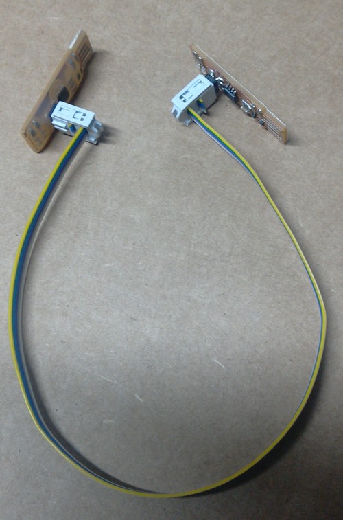
(5) Then a 30CM FRC 6-wire cable was crimped (without crimping tool - with the help of the instructor we tried different techniques!) both ends onto two 6-pin connectors.
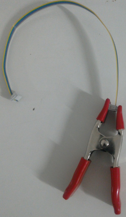 Semi automatic Crimping! |
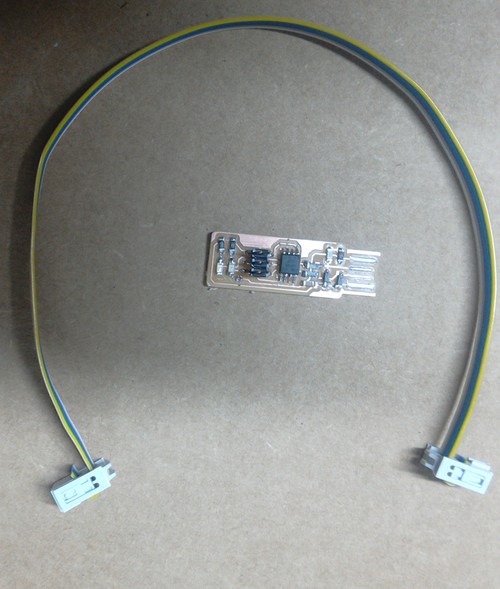 The cable and circuit |
(6) Then the PCB was connected to the 'programmer' circuit of the instructor. Meanwhile avrdude is installed and and proceeded as per the instructions in the page http://fab.cba.mit.edu/classes/863.16/doc/projects/ftsmin/index.html.
 The right polarity |
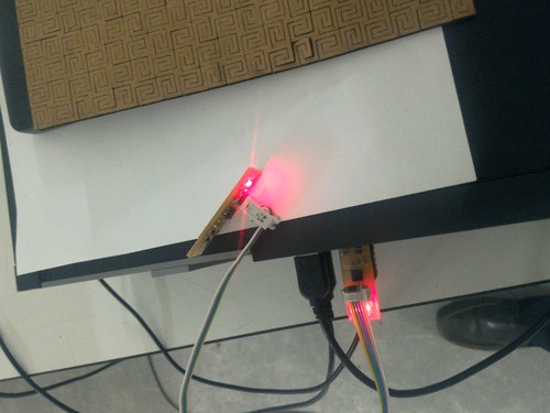 When connected for programming |
| avrdude installation --------------------------------- [fab@ask ~]$ sudo pacman -S avrdude gcc-avr avr-libc make [sudo] password for fab: error: target not found: gcc-avr warning: make-4.2.1-1 is up to date -- reinstalling [fab@ask ~]$ sudo pacman -S avrdude avr-libc resolving dependencies... looking for conflicting packages... Packages (8) avr-binutils-2.27-2 avr-gcc-6.3.0-1 confuse-3.0-1 elfutils-0.168-1 libftdi-1.3-3 libusb-compat-0.1.5-1 avr-libc-2.0.0-1 avrdude-1:6.3-2 Total Installed Size: 120.47 MiB :: Proceed with installation? [Y/n] y ..... |
Downloaded the firmware from http://fab.cba.mit.edu/classes/863.16/doc/projects/ftsmin/fts_firmware_bdm_v1.zip. Further steps |
(7) To get rid of the requirement of root permission to communicate with the USB PCB, I have created a file
/etc/udev/rules.d/50-usb-devices.rules as per


                  the instruction in the instructor's page http://archive.fabacademy.org/archives/2016/fablabtrivandrum/students/281/w6/w6.html
USB Permission
to user |
|
(8) make flash was still showing error! Instructor asked to check - avrdude -c usbtiny -p t45 -v. Error exists. First suspect was by module. Meanwhile another person was ready with his module. Tried error there still. Cable checked again error. Exploration by the instructor revealed that the issue was with his module!! After the demo he has done some protective coatings to the module which lead to a loose contact at a fragile joint!!! Anyway when connected with another module, the rest of the process was smooth and the module made into a 'programmer' too quickly!!
| make flash error! --------------------------- [fab@ask fts_firmware_bdm_v1]$ sudo make flash [sudo] password for fab: avrdude -p attiny45 -c usbtiny -P usb -e \ -U flash:w:fts_firmware.hex avrdude: initialization failed, rc=-1 Double check connections and try again, or use -F to override this check. avrdude done. Thank you. make: *** [Makefile:61: flash] Error 1 |
Debugging (with wrong cable polarity
on my USB PCB) ----------------- [fab@ask fts_firmware_bdm_v1]$ avrdude -c usbtiny -p t45 -v avrdude: Version 6.3, compiled on Nov 6 2016 at 21:45:03 Copyright (c) 2000-2005 Brian Dean, http://www.bdmicro.com/ Copyright (c) 2007-2014 Joerg Wunsch System wide configuration file is "/etc/avrdude.conf" User configuration file is "/home/fab/.avrduderc" User configuration file does not exist or is not a regular file, skipping Using Port : usb Using Programmer : usbtiny avrdude: usbdev_open(): Found USBtinyISP, bus:device: 001:029 avrdude: Warning: cannot open USB device: Permission denied avrdude: Error: Could not find USBtiny device (0x1781/0xc9f) avrdude done. Thank you. |
| Debugging (polarity corrected) (((((((((((((((Error persists))))))))))))))))))) |
Now the the programmer circuit is
replaced !!! ((((((((((Error Gone!!))))))))))))) |
| The Programming!!!!! ------------------------------------ |
Then configure the microcontroller. |
| Then RST pin is converted as an I/O
pin. As a side effect the device becomes write
protected!! (((((((DONE!!!))))))))))) |
Finally the testing. (1) This ckt is used to blow another ckt. (2) Another ckt was connected to my ckt as master and checked its I/O ability. (((Success)))) |
So the ISP PCB is milled, circuit is soldered, processor is burned, and tested - successfully.
We have not disconnected the VCC from the Vprog ,which according to our instructor is not necessary!