Week-9 :- Mechanical design
This week assigment is to build a project. We are five member team. The following are our team members including me.
Aneesh S Krishnan
Lancy Felix
Ahammed Siraj K K
Tanvir Nasser nagore
Suhail Pakkada
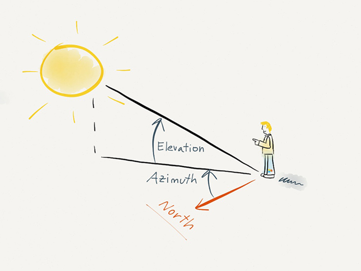
Azimuth and Elevation angle
The azimuth (az) is the angle between a celestial body (sun, moon) and the North, measured clockwise around the observer's horizon. It determines the direction of the celestial body.
The elevation (el) angle, also called the altitude, of an observed object is determined by first finding the compass bearing on the horizon relative to true north, and then measuring the angle between that point and the object, from the reference frame of the observer. Elevation angles for objects above the horizon range from 0 (on the horizon) up to 90 degrees (at the zenith).
Celestial Tracker
Our first intention was to build a solar tracker, which would track the sun to collect maximum sunlight, later we decided to make Celestial Tracker.
However the Celestial Tracker works almost like the solar tracker, except it carrys a telescope. We are planning to capture image using a webcam connected to telescope, since it
would be difficult to move around to watch Celestial bodies through telescope alone.
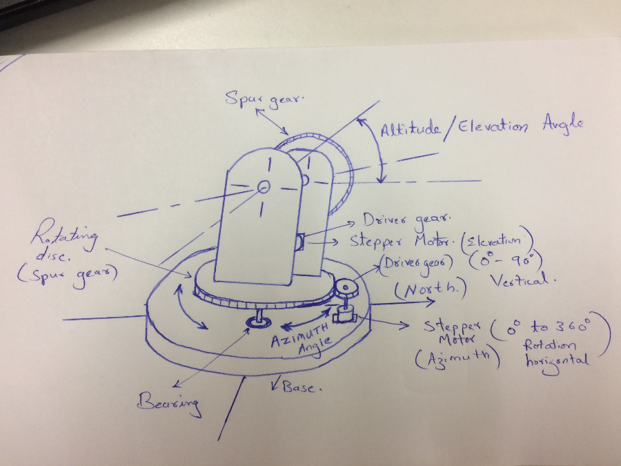
Base:- The whole wait is supported by base, hence we opted a base with 500mm diameter for attaining stablity. The north
south directional arrows are marked onto the base. It would be very easy to align base with magenetic compas.
Rotating disc:- The rotating disc is mounted on base, the bearing is assembled with base plate through a shaft and bearing. The bearing and the base plate groove is designed for tight fit. The outer diameter of the bearing is 26mm where as the corresponding slot is 25.5mm. The rotating disc is equipped with a spur gear disc.
Azimuth stepper motor:- This stepper motor is mounted on the base plate. Stepper motor is equipped with the driver gear.
Spur gear:- Spur gear is supposed to be realised from acrylic sheet (which is available in fablab). Hence, we opted a gear ratio of 1:10 for attaining precise anglular points.
We fixed the smaller driver gear size (Da) and teeth (Na). The geear size of the driven gear can be calculated using simple equation DaNb=DbNa.
Elevation stepper motor:- This stepper motor is mounted on the side plate. Stepper motor is equipped with the driver gear.
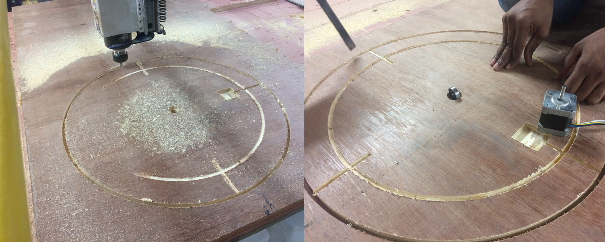
Realising the base plate
The base plate has been realised from 18mm plywood. The baseplate holds bearing and stepper motor.
The design files for the side plate can be downloaded here.
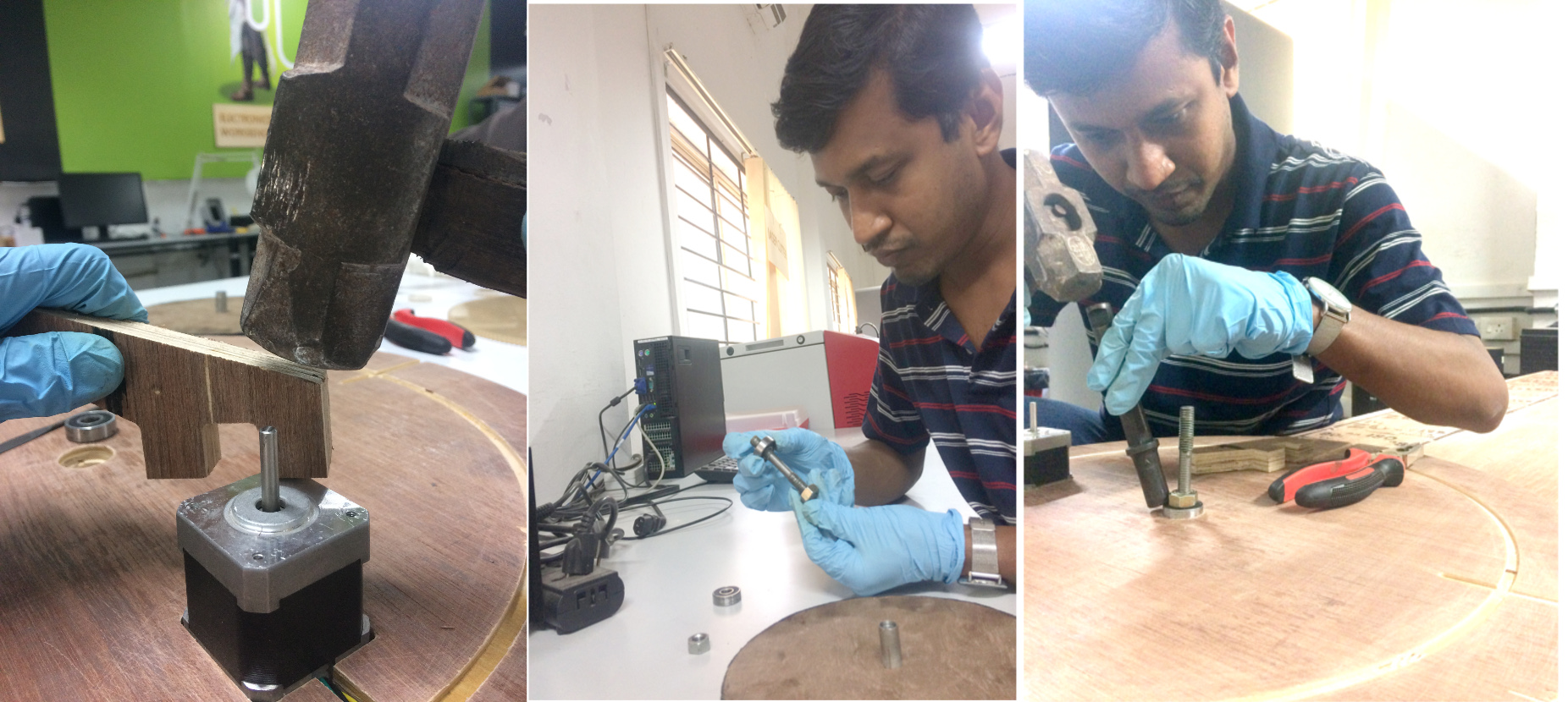
The stepper motor and bearing is fixed with the baseplate. A soft material can be used while
providing extra force with a mallet. The bearing holds tightly with its socket. We have followed the standard procedure
while fixing the bearing, all of its force have been allowed to transfer through its outer ring only.
The rest of the designing are covered under group project page, Click
here.