Week-8 :- Embedded programming
This week assigment is to learn about microcontroller and read its data sheet.
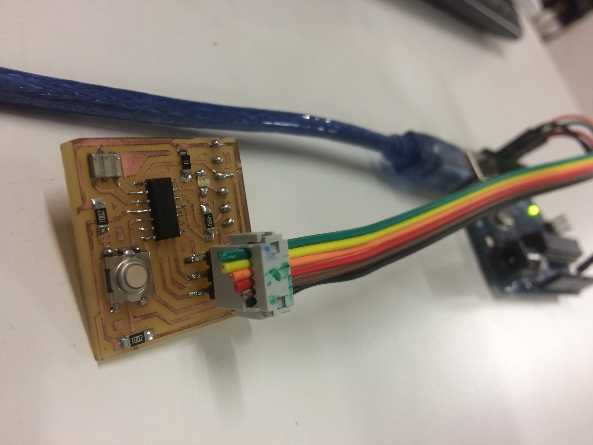
One of the PCB, I have designed during my previous assigment (Week-6 :-Electronics design) can be used here for programming.
That PCB contains an LED and a switch connected to Attiny44A microcontroller. I have gone through the its data
sheet and learned a few information about the chip. The microcontroller Attiny44A data sheet can be downloaded here.
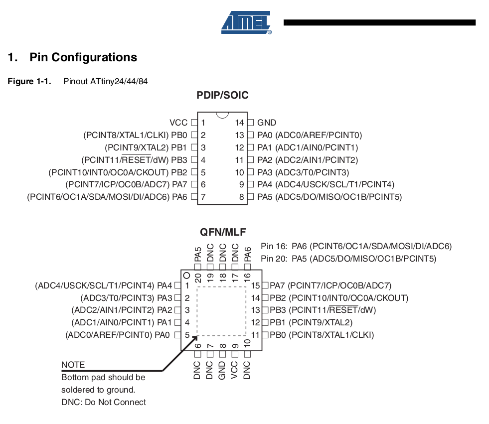
The pin configuration of the microcontroller from its data sheet is shown below.
I am from mechanical engineering background and this is the first time dealing with microcontroller. The following are
some important points which i would like to highlight.
A microcontroller contains one or more CPUs (processor cores) along with memory and programmable input/output peripherals.
Microcontrollers fetch the input and compute according to the program and gives the result.
Microcontrollers were originally programmed only in assembly language, but various
high-level programming languages, such as C, Python and JavaScript are now in
common use to target microcontrollers and embedded systems.
Clock frequency:- All microcontroller are running at a particular frequency depending upon its interal clock.
This is called internal clock frequency. We could add an external resonator/oscillator and alter its frequency by external means. This is called external
clock frequency.
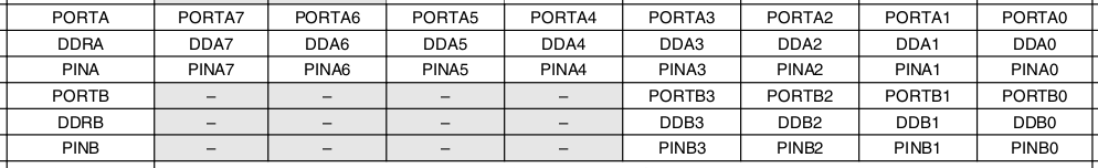
Ports and pins:- Ports are represented by registers inside the microcontroller, and allow the program to read the state of the pins if they are configured as inputs. (The pins are what stick out of an IC, and connected electrically).
The pin can be configured as an input or output. The ports and pins can be verified using data sheets.
Attiny44 have 8 pins at PORTA and 4 pins at PORTB. Each pin specification details are mentioned below.
AVR-GCC compiler
AVR-GCC is a compiler that takes C language high level code
and creates a binary source which can be uploaded into an AVR micro controller.
Thus AVR-GCC might be regarded as a 'C' cross compiler for producing AVR code.
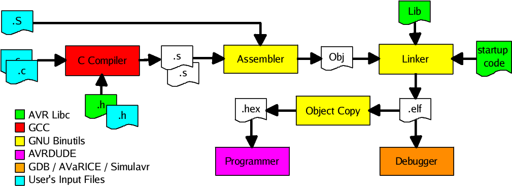
Once code in 'C' is written for a particular project AVR-GCC will turn C code into
assembly language files. AVR-libc includes all the header files that contain the
addresses of port and register names. Individual assembler files are then converted
into object files. Object files are files of code that AVR chips could run.
The linker AVR-ld will take all these assembler files, and cross-reference
functions names to create one single object file. The linker will also take modules
from the 'C' library and make them into a single object. Normally this linked
object is in ELF format and furthermore AVR-objcopy is used to generate a HEX
format file. The hex file can be flashed to the chip using programmer. The above
mentioned details are simply depicted below.
The first program using AVR-GCC compiler
The main lines of codes are described below.
#include <.avr/io.h> :- This imports the constants relating to your AVR chip into the program. When you compile the program,
you must specify the type of AVR chip that you use.
#include<.util/delay.h> :- This includes the function to pause the chip during the loop.
#define F_CPU 20000000 :- This defines the frequency of microcontroller.
DDRA =0b00000100 :- DDRA (Data direction register) defines the corresponing bit in port A as an input or output respectively. Here in this case 0b represented binary digit representation
followed by port specified by one or zero. 1 is defined as output ports and 0 for input.
PINB = 0b0100 :- The pins can be assigned high or low using binary digit representation. 1 for high and 0 for low.
_delay_ms(100) :- This will delay the process by 100 milli-seconds.
A simple program for blinking LED is shown below
The below program is to be saved as a file with .c extension. You can use any program
editor softwares for the same. I have written the text (program) using atom software and saved
it as file ledflash.c. The same can be downloaded here.
#include < avr/io.h>            //Import constants related to AVR chip.
#define F_CPU 20000000          // External frequency of crystal oscillator.
#include < util/delay.h>        // delay for LED
int main(void)
{
 DDRA=0b00000100;               // Set PA2 as Output port.
 while(1)
   { PORTA=0b00000100;          // LED high at port PA2.
    _delay_ms(100);             // Delay of 100 milli seconds.

    PORTA=0b00000000;           // LED low at port PA2.
    _delay_ms(100);             // Delay of 100 milli seconds.
   }
}
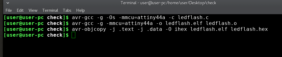
The programming steps using AVR GCC compiler is mentioned below. Open the terminal and enter the following commands.
 avr-gcc -g -Os -mmcu=attiny44a -c ledflash.c
 avr-gcc -g -mmcu=attiny44a -o ledflash.elf ledflash.o
 avr-objcopy -j .text -j .data -O ihex ledflash.elf ledflash.hex
The above three commands will generate the OBJ file followed by ELF file and HEX.
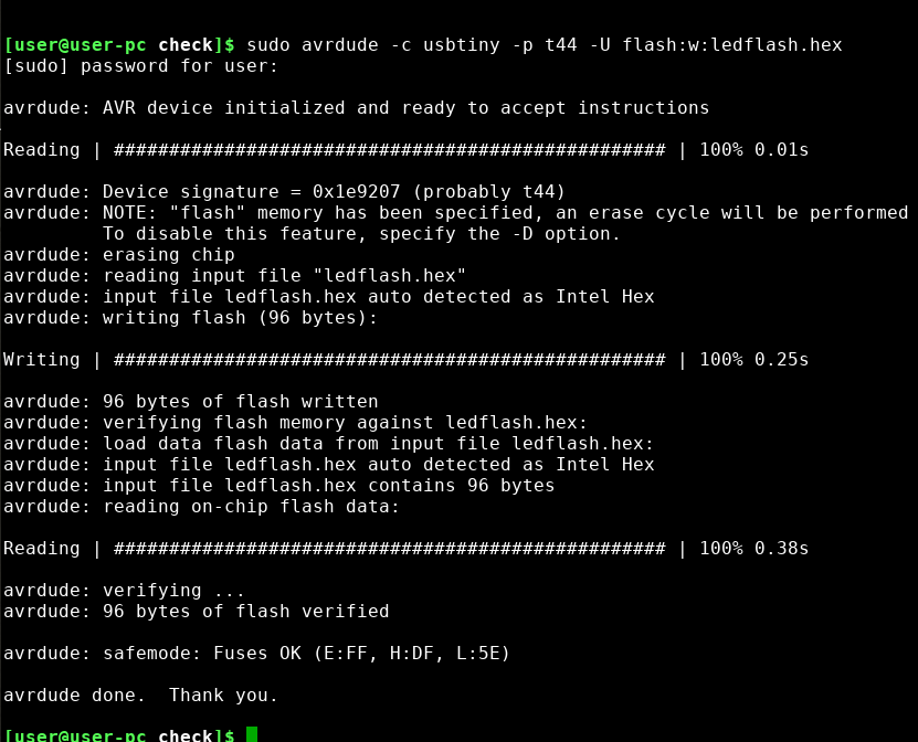
After compiling the HEX file, the program can be flashed to chip using the below command.
sudo avrdude -c usbtiny -p t44 -U flash:w:ledflash.hex
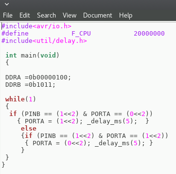
A latching switch using AVR
A latching switch is a switch that maintains its state after being activated.
A push-to-make, push-to-break switch would therefore be a latching switch - each time
you actuate it, whichever state the switch is left in will persist until the switch is
actuated again. The program for latching switch and its video is given below. The program
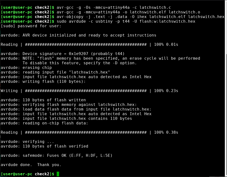
is flashed using the following commands in terminal window.
   avr-gcc -g -Os -mmcu=attiny44a -c latchswitch.c
   avr-gcc -g -mmcu=attiny44a -o latchswitch.elf latchswitch.o
   avr-objcopy -j .text -j .data -O ihex latchswitch.elf latchswitch.hex
   sudo avrdude -c usbtiny -p t44 -U flash:w:latchswitch.hex
The above three commands will generate the OBJ file followed by ELF file and HEX. The same can be downloaded here.
Alternative method for running avr-gcc compiler using Arduino Software (IDE)
Arduino Software (IDE)
The Arduino system is based on the avr-gcc compiler and makes use of the standard
AVR libc libraries, which are open-source C libraries, specifically written for
Atmel hardware. By default the arduino software doesnt contain Attiny 44 chip librarys. We need to include
the deatils manually. Each steps for programming and installing the librarys are depicted below.
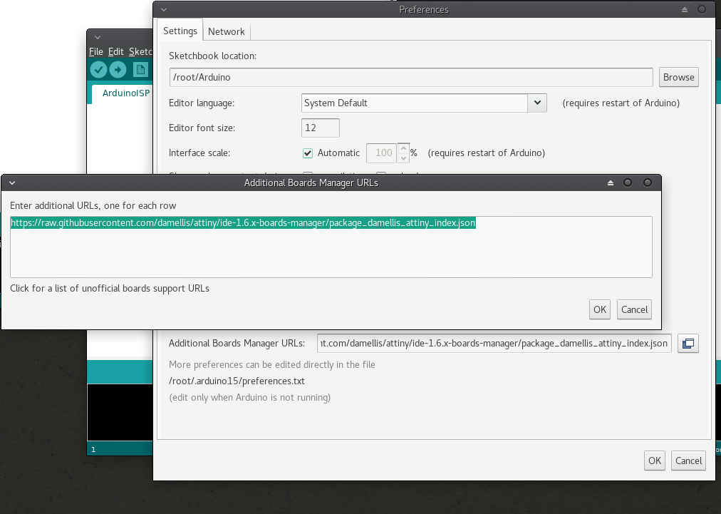
Open arduino software and click File>preference>setting> Click add board manager.
Enter the following link. click ok.
https://raw.githubusercontent.com/damellis/attiny/ide-1.6.x-boards-manager/package_damellis_attiny_index.json
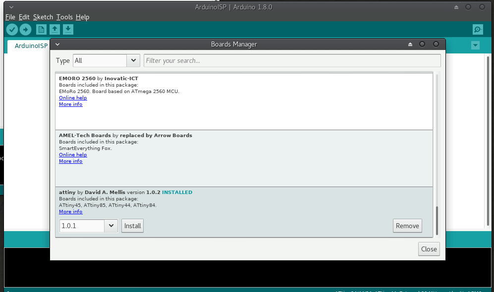
After adding the link click>Tools>board>board manger> Select attiny and click install.
Now we had added the attiny librarys.
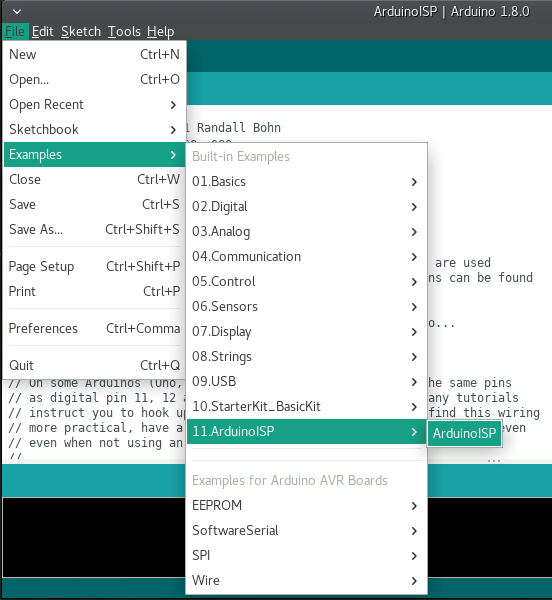
In the next step, an ISP programmer is required to program the new chip (attiny44). So, we can turn arduino into ISP programmer.
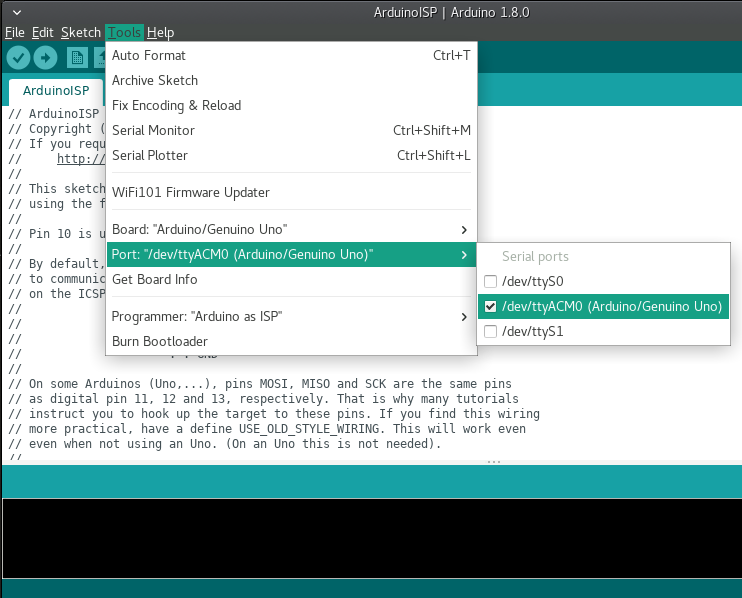
Connect arduino, go to File>example>arduinoisp>arduinoisp.
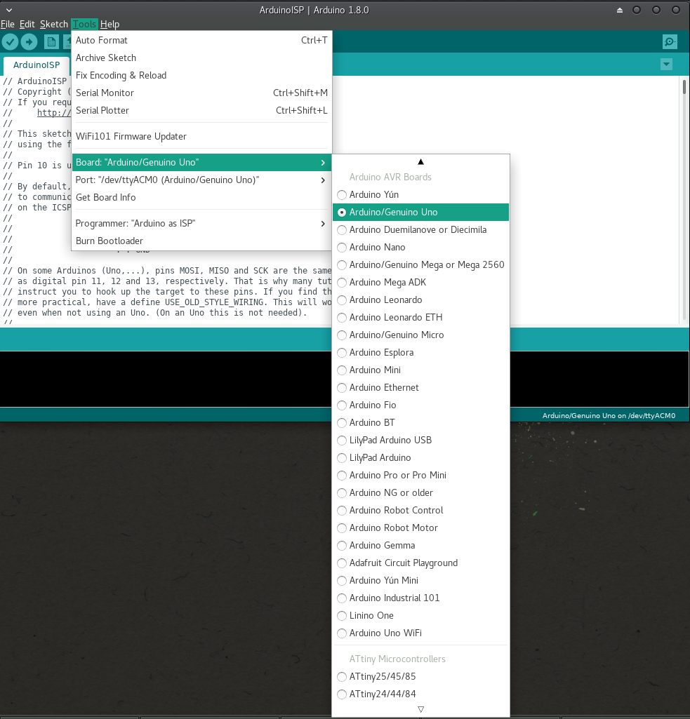
Select Your arduino Uno board.
Select the port, where arduino is connected.
If you could not find the required port, go to network settings to identify the port.
Copy and paste the above program (blinking LED or latching switch program) in arduino window.
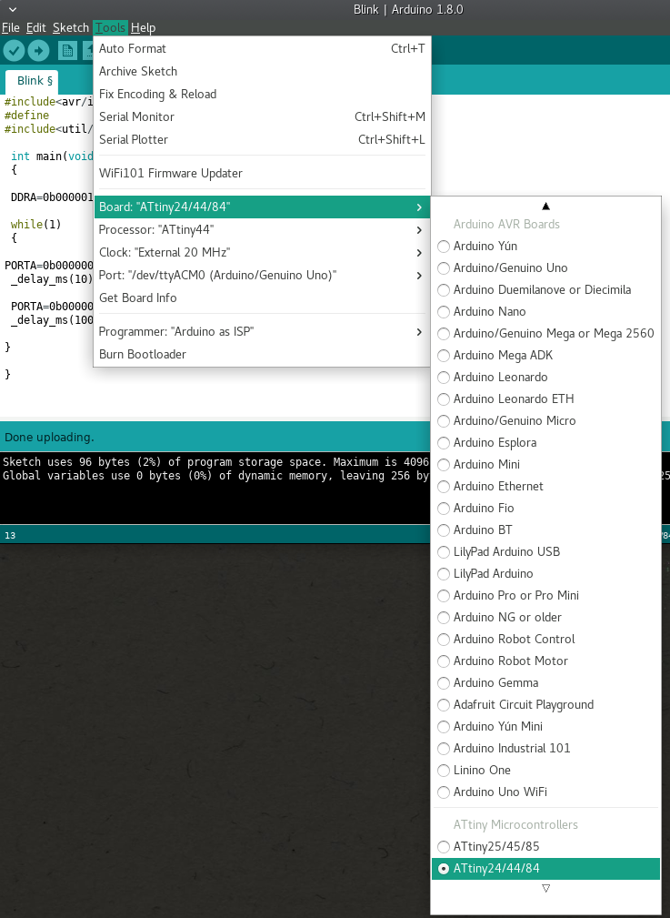
Select Tools>board>attiny44.
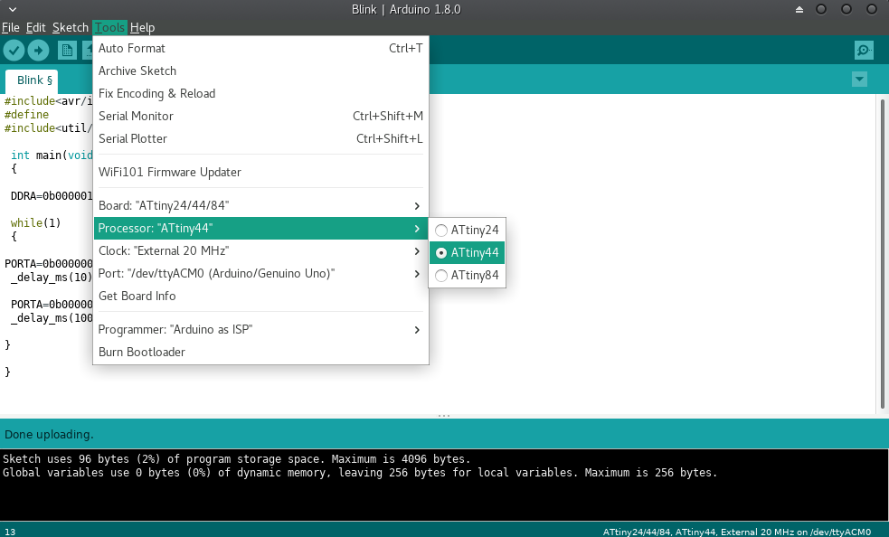
Select the processor type> Attiny44.
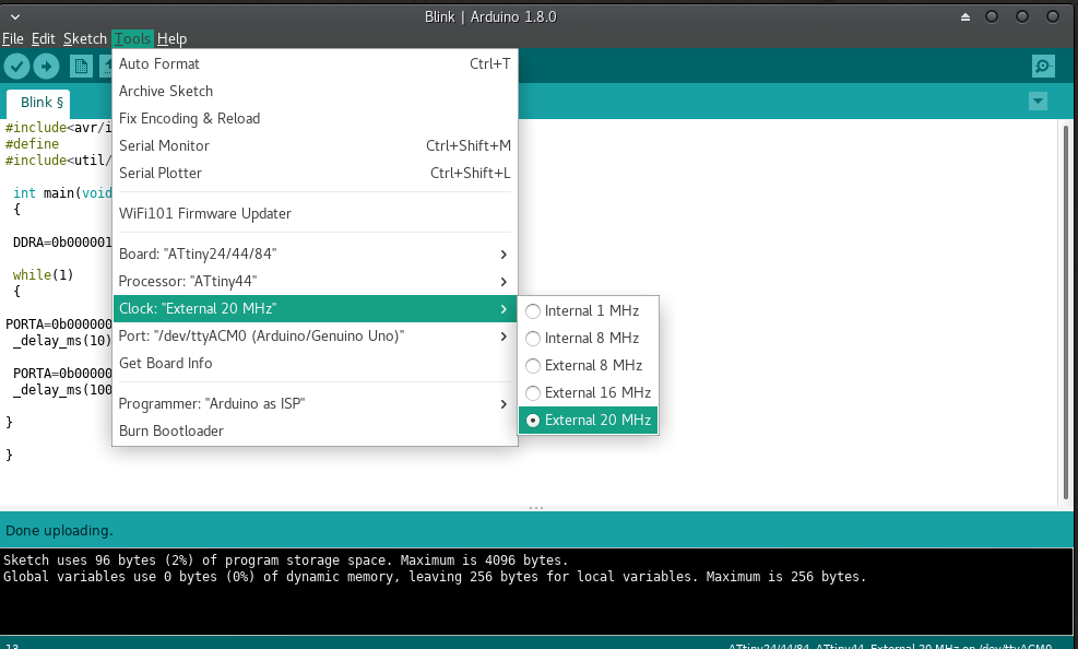
Select the clock frequency. By default, the internal clock frequency of the chip is 8 Mhz.
But we have connected a 20 Mhz crystal oscillator externally, hence the chip can handle upto 20 Mhz.
Select the port.
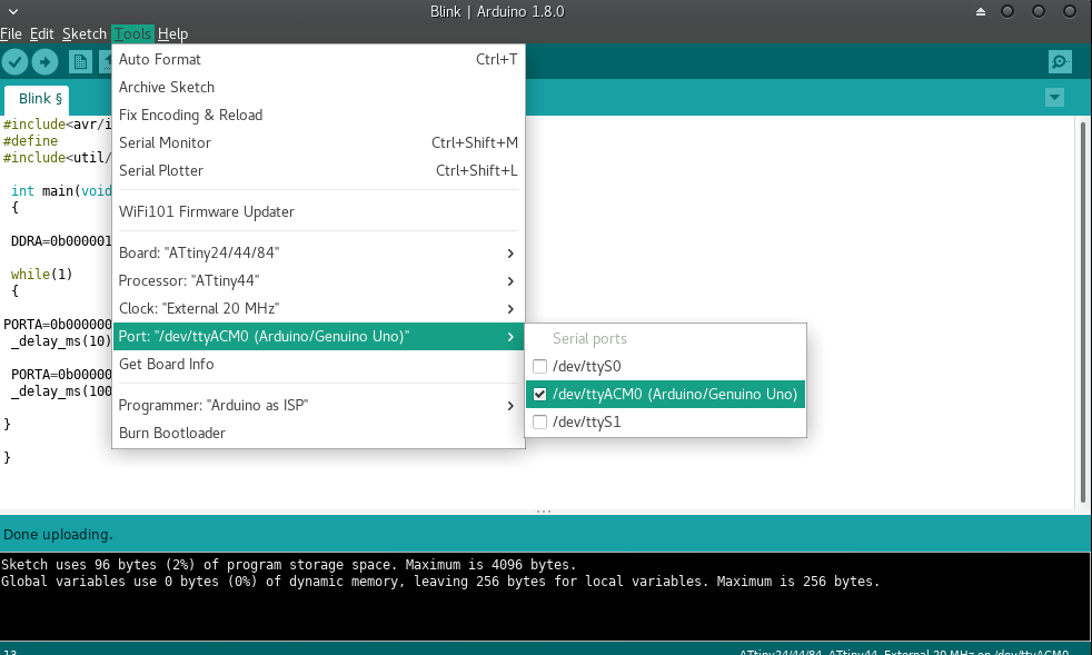
Now, select the programmer. In our case arduino is the programmer. So, Click arduino as ISP.
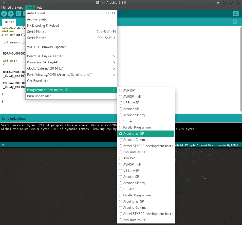
The list of ports for connecting ISP are specified in the arduino ISP program itself.
The details of ISP to arduino pin configuration is shown below.
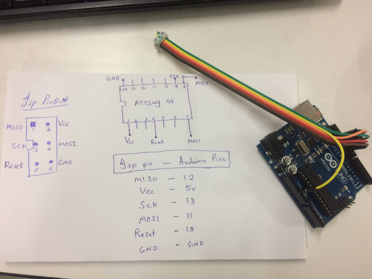
Attiny44 chip is connected to ISP connector. make sure all the tracks are correct and connected to attiny 44 pins according th the above diagram.