week4
Week-5 :-3D scanning and printing
A 3D scanner is a device that analyses a real-world object or environment to collect
data on its shape and colour. The collected data can then be used to construct
digital three-dimensional models. Many different technologies can be used to build
these 3D-scanning devices; each technology comes with its own limitations,
advantages and costs.
A 3D print/model is a digital representation of a physical object.
This is done by processing the raw data gathered during a 3D scan into a digital model that
can then be used for many purposes.
We have two printers in Fablab, Ultimaker 2 and Dimension SST 1200es. Polylactic Acid (PLA)
are Acrylonitrile butadiene styrene (ABS) materials spools are used for printing. The main advantages
of materials are mentioned below.
ABS - Its strength, flexibility, machinability, and higher temperature resistance
make it often a preferred plastic for engineers, and professional applications.
PLA - The wide range of available colors and translucencies and glossy feel makes
it best for for display or small household uses, the plant based origins and
the semi-sweet smell has got the advantage over ABS. PLA is a bio-degradable plastic
material that has gained traction with 3D printing for this very reason. It can be
utilized in resin format for Digital Light/Stereolithography Processing (DLP/SL) processes as well as in filament form for the
Fused deposition modeling (FDM) process When properly cooled.
PLA seems to have higher maximum printing speeds, lower layer heights, and sharper
printed corners. Combining this with low warping on parts make it a popular plastic
for home printers.
3D scanning
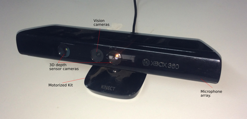
Kinect is a line of motion sensing input devices by Microsoft for Xbox 360 and Xbox
One video game consoles and Windows PCs.Kinect uses an RGB camera with depth sensor
and infrared projector with a monochrome CMOS sensor which sees the environment
not as a flat image, but as dots arranged in a 3D environment. Like a game
controller, the Kinect is an input device for the Xbox One. It can be used to
identify who's playing the Xbox One, to sense the position of your body to control
things on the screen, and to listen and react to voice commands.The device provides
a natural user interface (NUI) that allows users to interact intuitively and
without any intermediary device, such as a controller.
Vision camera - This video camera aids in facial recognition and other detection
features by detecting three color components: red, green and blue. Microsoft calls
this an "RGB camera" referring to the color components it detects.
Depth sensor - An infrared projector and a monochrome CMOS (complimentary
metal-oxide semiconductor) sensor work together to "see" the room in 3-D regardless
of the lighting conditions.
Multi-array microphone - This is an array of four microphones that can isolate
the voices of the players from the noise in the room.
The new 3D Scan app allows you to scan an object while holding Kinect in your hands.
Either rotate around the object you are scanning and turn the handheld mode on,
or use a turntable. If you use a turntable, put Kinect on a tripod and turn the
handheld mode off.
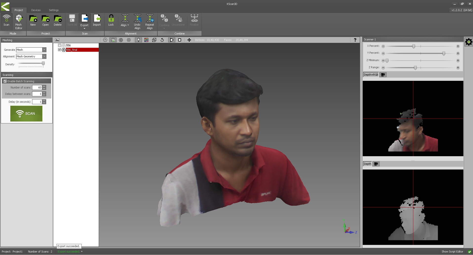
Kscan3D
Kscan3D is a 3D scanner tool for kinet. Free version for the same is available. I have downloaded
the same. KScan3D converts this data into a 3D mesh, it capture data from multiple
angles to create a complete 360 degree mesh and align 3D meshes automatically.
After completing the model can be exported in .fbx, .obj, .stl, .ply, and .asc formats.
I had sat on a rotating chair and 60 pictures in total were taken (automatically) for 360 degree complete chair rotation.
Once after taking the photos, all photos can be aligned with in a single click (align option). Click meshing tool, this tool will mesh all
the pictures and will generate a smooth contour with exact color contrast 3D model. Once after checking the model, it can be exported to stl file for 3D printing.
The below image depicts the 3D modell scanned using the same kscan3D software. The same model can be downloaded
here.
3D Printing
3D printing or additive manufacturing is a process of making three dimensional solid objects from a digital file.
The creation of a 3D printed object is achieved using additive processes. In an
additive process an object is created by laying down successive layers of material
until the object is created. Each of these layers can be seen as a thinly sliced
horizontal cross-section of the eventual object.
There are several ways to print and all those available are additive,
differing mainly in the way layers are build to create the final object.
Some methods use melting or softening material to produce the layers. Selective
Laser Sintering (SLS) and Fused Deposition Modeling (FDM) are the most common
technologies using this way of 3D printing.
Another method is curing a photo-reactive resin with a UV laser
or another similar power source which cure one layer at a time. The most common method
for this is called Stereolithography (SLA). In our Fablab, we have 2 printers which
are using Fused Deposition Modeling (FDM) process. The detailed image with specification for the
same is mentioned below.
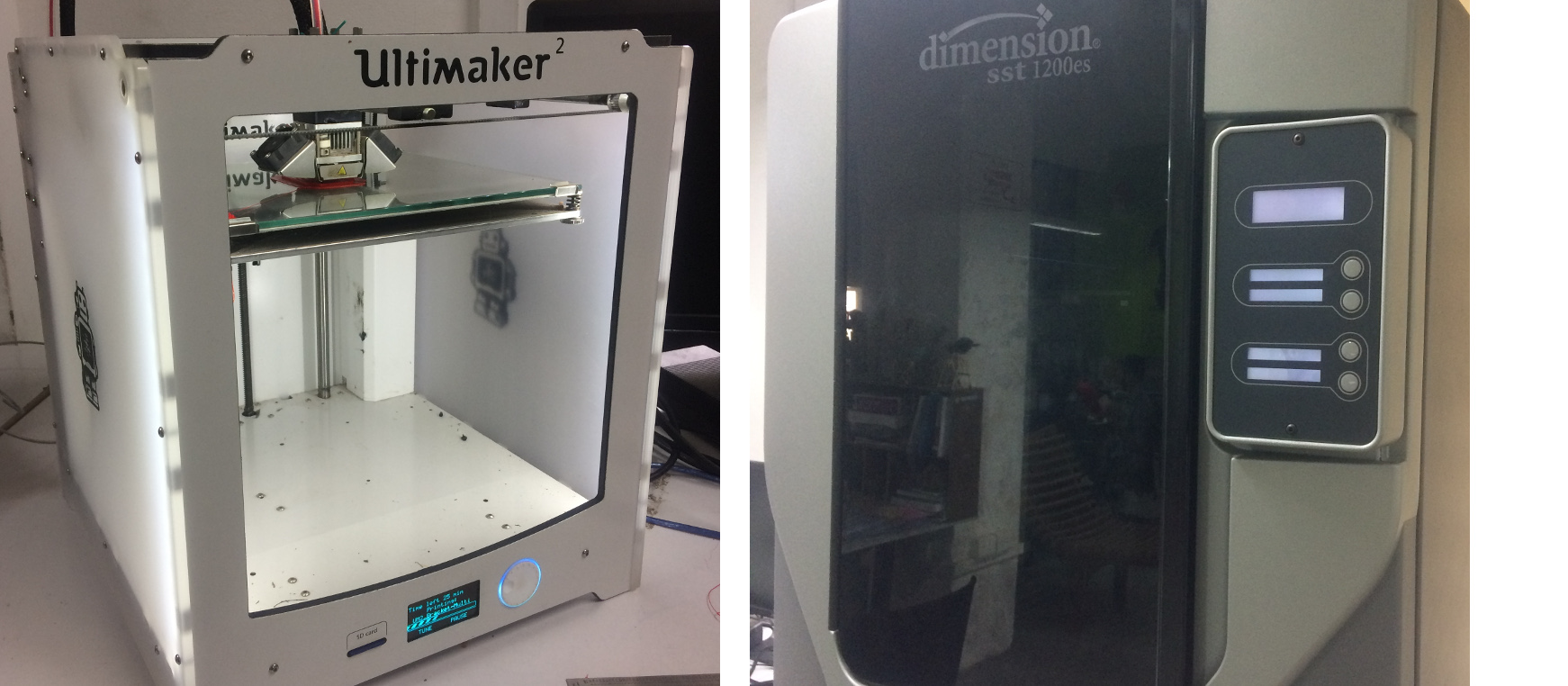
The specification of ultimaker 3D printer is mentioned below.
Print technology:- Fused Deposition Modeling (FDM)
Supported materials:- PLA, ABS, CPE
Build volume:- 210 x 210 x 205 mm max
Layer resolution:- 0.2 mm to 0.020 mm
Nozzle diameter:- 0.4 mm
XYZ accuracy:- 12.5, 12.5, 5 micron
Nozzle temperature:- 180 °C to 260 °C
Operating sound:- 57 dBA
Supported file types:- STL
Software for ultimaker printer:- cura
The specification of dimension 3D printer is mentioned below.
Print technology:- Fused Deposition Modeling (FDM)
Supported materials:- ABS
Build volume:- 254 x 254 x 305 mm max
Layer resolution:- 0.254 mm or 0.330 mm
Supported file types:- STL
Software for ultimaker printer:- catalyst software
Testing the limits of 3D printer
In order to check the limits, the following file is downloaded from thingiverse.com, the same can
downloaded here.
The below mentioned parameters are tested.
Nut, Size M4 Nut should fit perfectly
Wave, rounded print
Star, Sharp Edges
Name, Complex Shapes
Holes, Size 3, 4, 5 mm
minimal Distance: 0.1, 0.2, 0.3, 0.4, 0.5, 0.6, 0.7 mm
Z height: 0.1, 0.2, 0.3, 0.4, 0.5, 0.6, 0.7, 0.8, 0.9, 1.0, 1.1 mm
Wall Thickness: 0.1, 0.2, 0.3, 0.4, 0.5, 0.6, 0.7 mm
Bridge Print: 2, 4, 8, 16 mm
Sphere, Rounded Print 4.8mm height
Sphere Mix, 7 mm height
Pyramide, 7 mm height
Overhang: 25, 30, 35, 40, 45, 50, 55, 60, 65, 70°
Warp, does it bend?
3D Print Font, optimized for 3D printing
Surface, Flatness
Size, 100 x 100mm x 23.83 (10mm width)
Spike, minimum Layer Time, 21 mm height from Bottom (include Baseplate)
Hole in Wall, 4 mm diameter, check for proper print
Raft Test, raft should be just under the model
Retract Travel, check retract settings for longer travel
TRAIL 1
Ultimater 3D printer setting:
SPEED:100 mm/s INFILL SPEED:100 mm/s WALL THICKNESS SPEED:40 mm/s TOP/BOTTOM SPEED: 40 mm/s TRAVEL SPEED: 200 mm/s SUPPORT:RAFT AIRGAP:0.2 mm INITIAL Z OVERLAP:0.1 mm RAFT TOP LAYER: 2 LAYER HEIGHT:0.1 mm WALL/TOP/BOTTOM THICKNESS:0.8 mm INFILL: 30% RETRACTION:6.5 mm
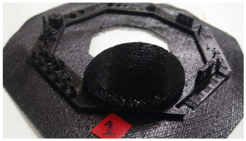
As you can see from the result above that the model has a lot of errors , like webbing and incompletness.
The base of the dome structure has many holes, this may be caused due to retraction being high, from the adjacent structure.
TRAIL 2
Ultimater 3D printer setting:
SPEED:100 mm/s INFILL SPEED:100 mm/s WALL THICKNESS SPEED:40 mm/s TOP/BOTTOM SPEED: 40 mm/s TRAVEL SPEED: 200 mm/s SUPPORT:RAFT AIRGAP:0.2 mm INITIAL Z OVERLAP:0.1 mm RAFT TOP LAYER: 2 LAYER HEIGHT:0.1 mm WALL/TOP/BOTTOM THICKNESS:0.8 mm INFILL: 30% RETRACTION: 2 mm
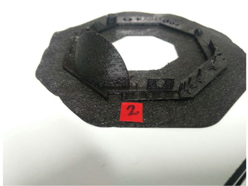
Here we decreased, the retraction from the default 6.5 mm to 2 mm, to counter the effects , as we saw in the previous trial.
As you can see from the result above that the base of the dome ,even though improved from the previous trial, still has the holes.
The retraction needs to be reduced even more.
TRAIL 3
Ultimater 3D printer setting:
SPEED:100 mm/s INFILL SPEED:100 mm/s WALL THICKNESS SPEED:40 mm/s TOP/BOTTOM SPEED: 40 mm/s TRAVEL SPEED: 200 mm/s SUPPORT:RAFT AIRGAP:0.2 mm INITIAL Z OVERLAP:0.1 mm RAFT TOP LAYER: 2 LAYER HEIGHT:0.1 mm WALL/TOP/BOTTOM THICKNESS:0.8 mm INFILL: 30% RETRACTION:1.5 mm
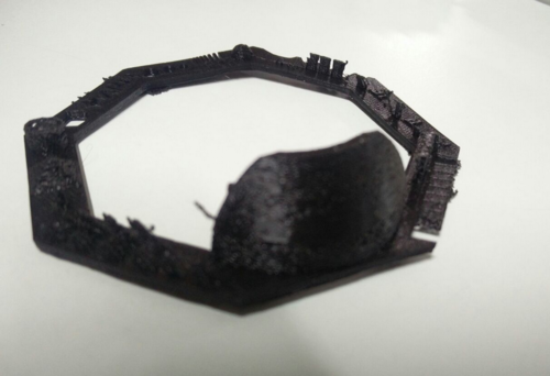
Here, we have decreased the retraction even further.
As you can see from the result above that the model still has the incompletness issue at various locations.There is also lot of webbing in the inverted hemispherical area.
Also, the bridge isnt properly completed.This may be due to less infill rate.
TRAIL 4
Ultimater 3D printer setting:
SPEED:100 mm/s INFILL SPEED:100 mm/s WALL THICKNESS SPEED:40 mm/s TOP/BOTTOM SPEED: 40 mm/s TRAVEL SPEED: 200 mm/s SUPPORT:RAFT AIRGAP:0.2 mm INITIAL Z OVERLAP:0.1 mm RAFT TOP LAYER: 2 LAYER HEIGHT:0.1 mm WALL/TOP/BOTTOM THICKNESS:0.8 mm INFILL: 60% RETRACTION:0 mm
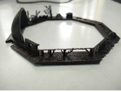
Here we have completely removed the retraction, and given a 0 mm value for it.Also the fill rate has been increased to counter the incompltness at some sites.
The incompletness of the bridge and the base of teh dome is also resolved.
The webbing inside the inverted hemisphere is also absent
The model, now matches almost to the desired output, and is taken as the best iteration.
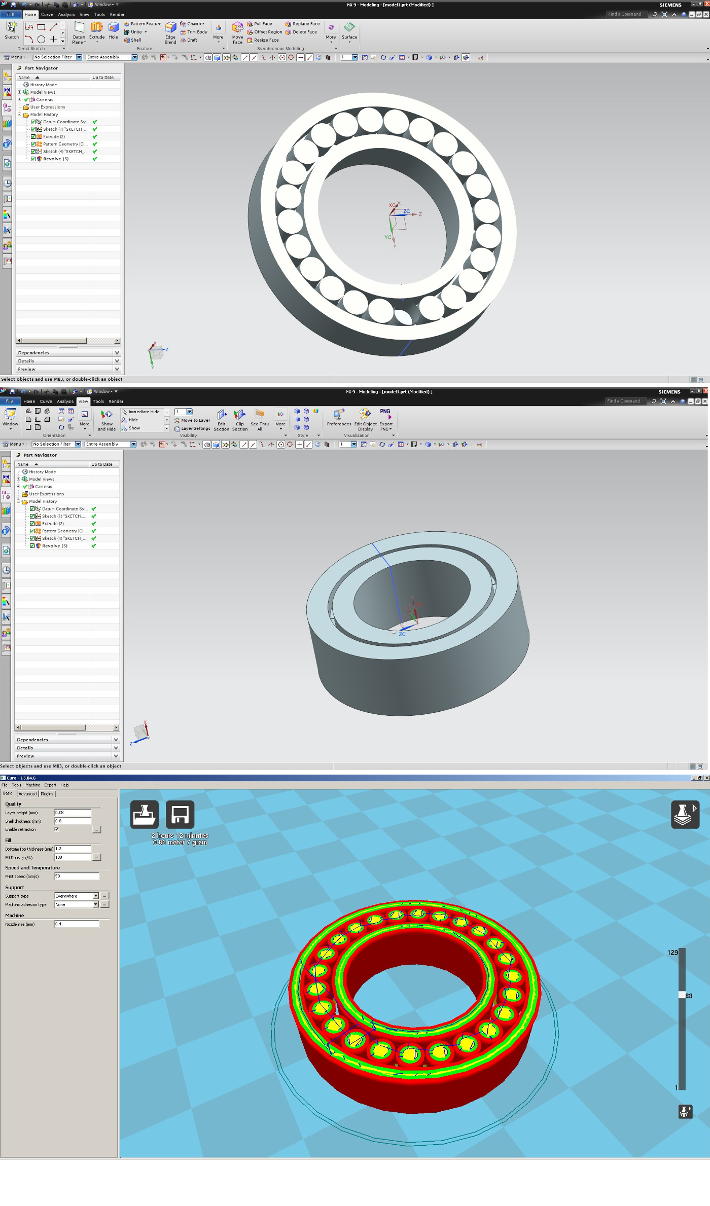
3D modelling and printing
I have designed a simple roller bearing. The overal size of the bearing is roughly 25 mm.
This bearing containg 24 rollers for a smooth rotation. The inside wall clearance is 0.25 mm.
Model wall thickness:- 2 mm.
Model wall thickness (top and bottom):- 2 mm.
Once after modelling, the bearing is expored to stl file. I am using ultimaker machine for the 3D print.
The bearing model need to converted to gcode file for printing. The software 'cura' comes with ultimaker machine
and its free to download. The cura settings, used for prinitng is mentioned below.
Layer thickness:- 0.08 mm.
Side wall thickness:- 1.2 mm
Top and bottom wall thickness:- 0.8 mm
Fill density:- 85%.
The 3D model of the bearing can be downloaded here.