Week-2 :- Computer aided design
CAD (computer-aided design) software is used by architects, engineers, drafters, artists,
and others to create precision drawings or technical illustrations. CAD software can be
used to create two-dimensional (2-D) drawings or three-dimensional (3-D) models.
2D cad drawings
2D CAD drawings are defined using basic geometric shapes like lines, rectangles,
circles, splines etc. to produce flat drawings. Those drawings can be projected on XY plane.
3D cad drawings
3D CAD drawings can be represented on XYZ surface. 3D drawings allows creation of 3D images that are realistic.
These images are called 3D models as they can be viewed and orientated in any axis X, Y or Z.
One can extract different views from a 3D model, such as isometrics or perspectives,
views.
3D CAD can be further classified as:
Wire-frame models – It is created by connecting each edge of the
physical object where two mathematically continuous smooth surfaces meet, or
connecting an object's vertices using straight lines or curves. They create skeleton like models with lines and arcs.
Since they appear to be made of wires, and everything in the background is visible,
they are called wire-frame models.
Surface models – These models are created by joining 3D surfaces.
Since nothing in the background is visible. It is created by connecting each plane or a series of
planes. Surface model lacks internal features.
Solid models – They are considered to be the most useful
CAD models. Although they appear to be the same as surface models, they also have additional
properties like weight, volume and density, just like actual physical objects.
These models are commonly used as prototypes to study engineering designs. All the internal
features are embedded in the model itself.
GIMP image editor
GIMP is a free image editor software available for windows and Linux.
It has many capabilities. It can be used as a simple paint program, an expert quality
photo retouching program, an online batch processing system, a mass production image
renderer, an image format converter etc. GIMP offers sophisticated tools for editing image. Some of the basic tools are changing
image dimensions, size, croping, flip etc. are availble in GIMP. 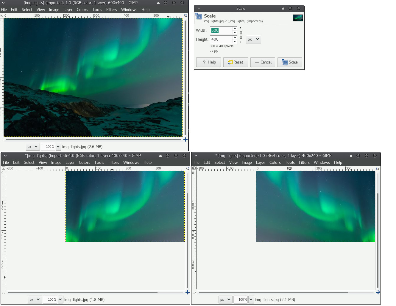
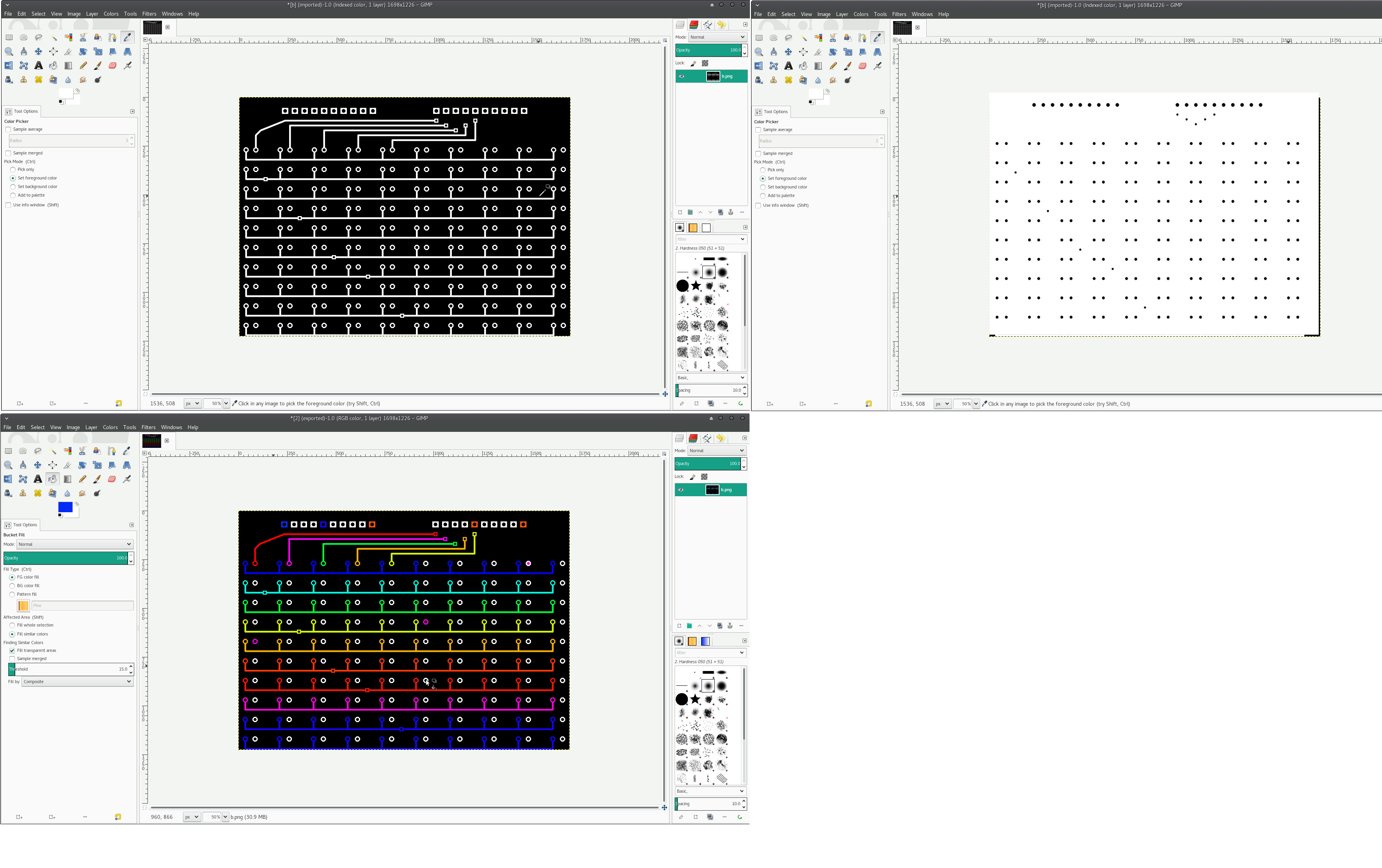
GIMP for Editing PCB schematics
I have imported image from Eagle software for editing with GIMP. The schematic shown
below is a part of my final project. It is a bouble sided PCB with 100 LEDS, and one of
its image is slected for GIMP project. Two major tools for picking and pasting color is descibed below.
Color picker tool:- This tool is most often used for the image edting. It allow us
pick colors from the webpage easily.
Bucket fill tool :- The bucket fill tool is used to fill an area with single specific color. This tool is very
usefull for editing PCB schematics. The PCB Milling machine detect the PCB tracks with specified
colors (Specialy black and white tracks). This tool helps to change the track color with a single click.
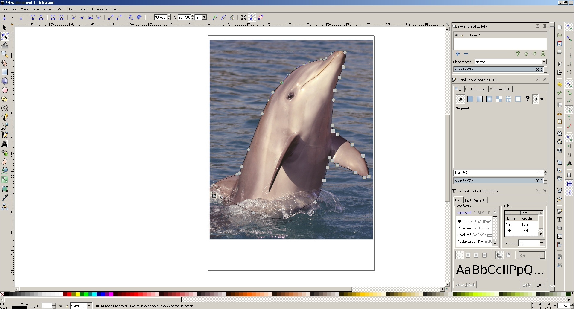
Vector softwares
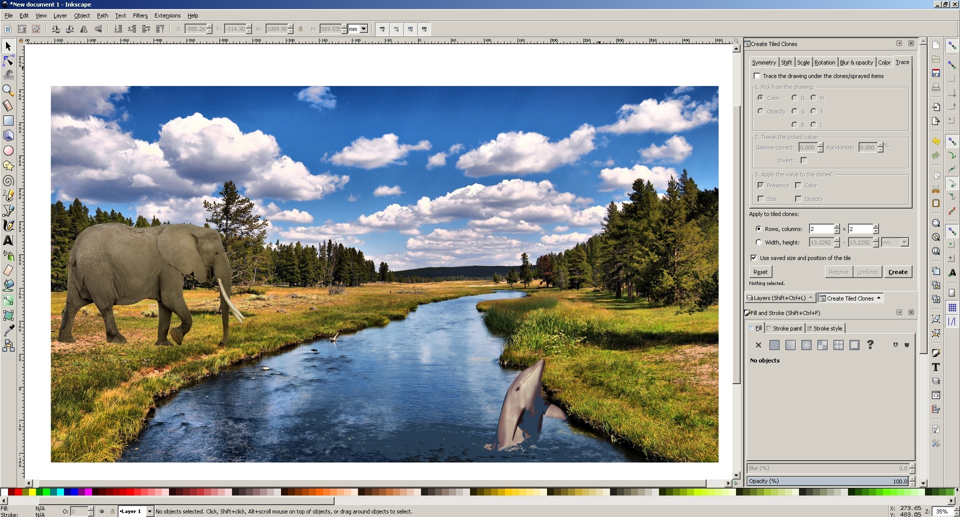
Inkscape
Inkscape is professional quality vector graphics software which runs on Windows and Linux.
It is used by design professionals and hobbyists worldwide, for creating a wide variety of graphic
such as illustrations, icons, logos, diagrams, maps and web graphics. Inkscape uses the W3C open
standard SVG (Scalable Vector Graphics) as its native format, and is free and open-source software.
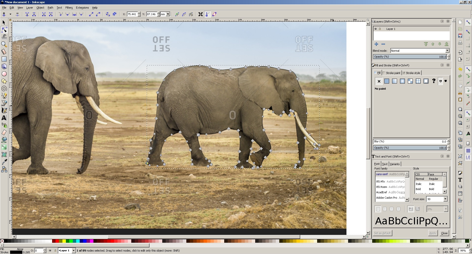
Inkscape has sophisticated drawing tools with capabilities comparable to Adobe Illustrator, CorelDRAW
. It can import and export various file formats, including SVG, AI, EPS, PDF, PS and PNG. It has a
comprehensive feature set, a simple interface, and is designed to be extensible;
users can customize Inkscape's functionality with add-ons.
AutoCAD
AutoCAD software is
used for mechanical product design and drafting applications
that cater to the various needs of the mechanical engineering companies , It comes
with a complete set of powerful drafting and detailing tools for drafting. It is a
simple enough software with friendly interface , It is easy to grasp and have simple
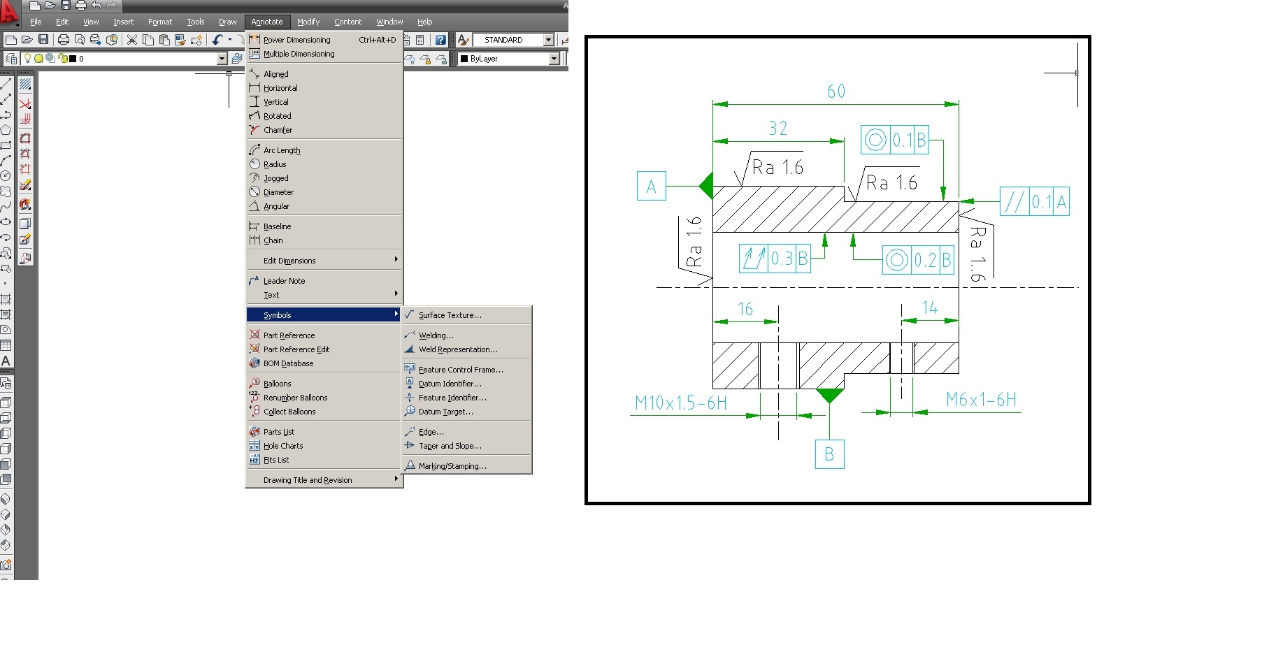
tools. AutoCAD supports most of the standard CAD files while importing. It also have
specific drafting tools for generating the standards Industry based geometric dimensions,
the surface texture symbols, the mechanical symbols and the weld symbols.AutoCAD
automatically redraw the geometry to illustrate the dashes and the hidden lines of parts
which are blocked by the other parts in the mechanical design, and drawings can be created
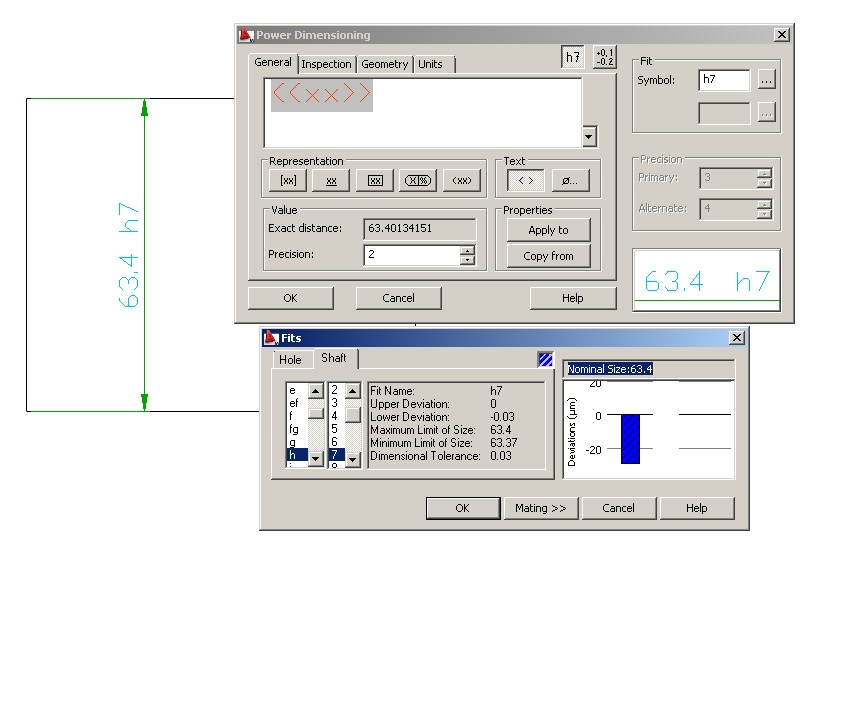
in 2D or 3D and rotated. This software contains standards and allow the designer to
check if the design is within the specification or tolerance limit. The fits and tolerance
details are available on Autocad.
The control features are very important in fabrication drawings along with tolerance.
Fabrication drawing of a pipe holder have been created in AutoCAD using Feature controlled
frame and datum features. While generating these types of fabrication drawings, the type
of machines and its limits are also considered.
I have been working with AutoCAD for quite somelong and just created drawing of Corner shelf in AutoCAD using the following commands.
Line:- Draw the Start point and end point of line.
Circle:- A center point, followed by diamter or radius.
Arc:- Create the start point, middle point and end point.
Trim:- Trim command is used to remove the unwanted edges.
Extend:- Used to entent a line.
Region:- Region command is used to create a surface. A surface (XY plane) is a
formed by a set of closed lines or arc.
Extrude:- An extrude command is used to extrude a surface (in XY plane) towards Z axis.
Corner shelf [Download File]
3D CAD software
Autodesk Inventor software
Autodesk Inventor is a 3D mechanical engineering, design, visualization, and
simulation software. Autodesk Inventor is a parametric and feature-based solid modeling tool. It allows you to convert the basic 2D sketch
into a solid model using very simple modeling options. In my personal opinion this is a good software
for beginners. Exploded views and presentationscan be easily created and connected with inventor.
The updating feature easily updates in models without altering other parameters..
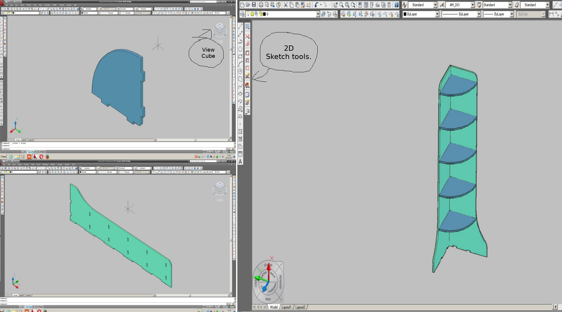
The first step is to create a solid model of the object using 2D sketch and 3D tools.
Second step is the process like creating a standard drawing in
either first or third angle projection method with different
views (like orthographic, isometric, auxiliary, sectional,
perspective) is completely automated.
The process of adding dimensions (with all standard
notations) to the drawing is also automated.
The software contain internaltional standards components like nuts, bolts etc.
Viewcube:- View Cube is used to switch between standard and trimetric views of the model.
Click the cube corners to snap the 3D model to trimetric views and click the faces to view orthographic views
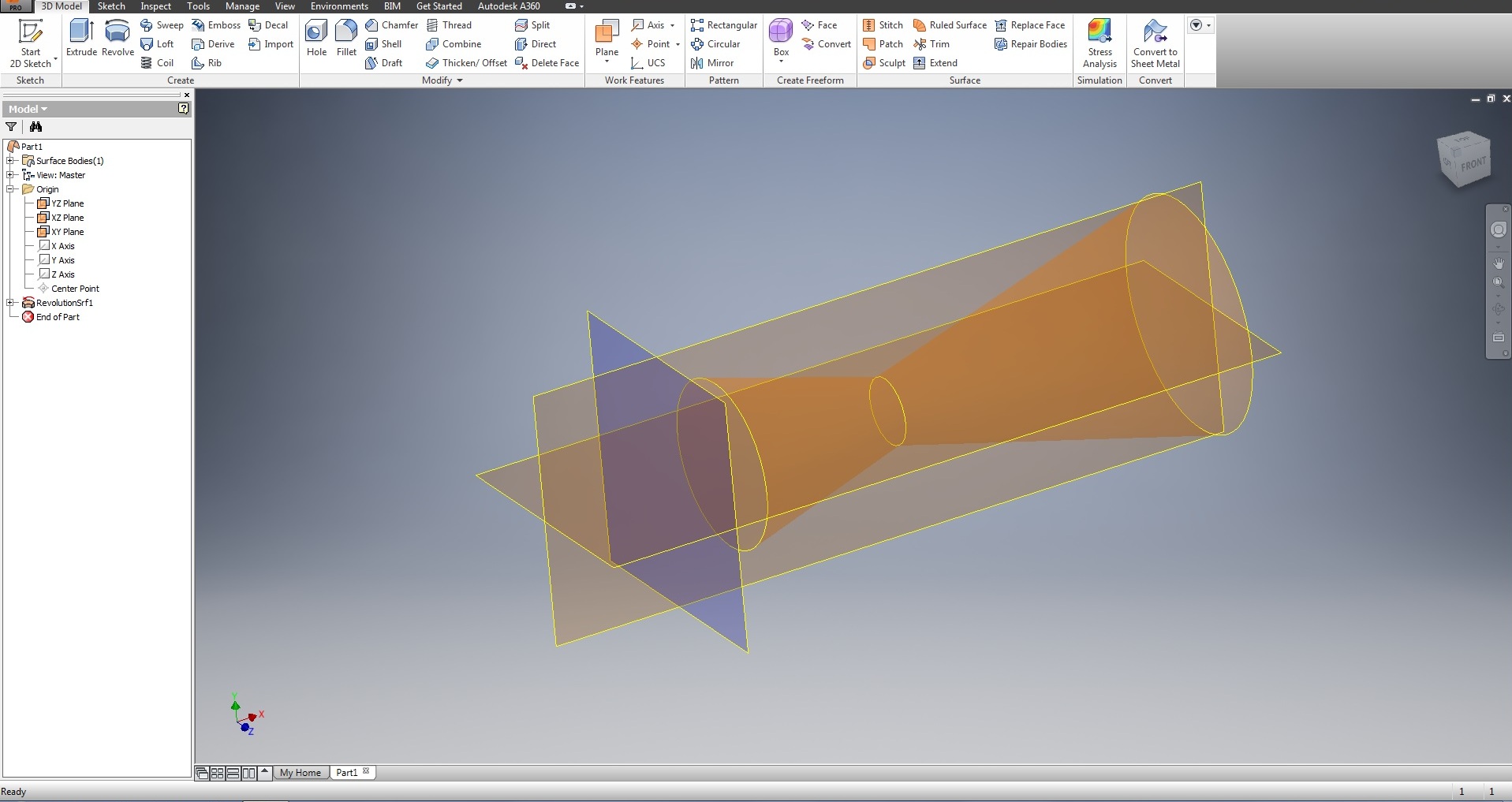
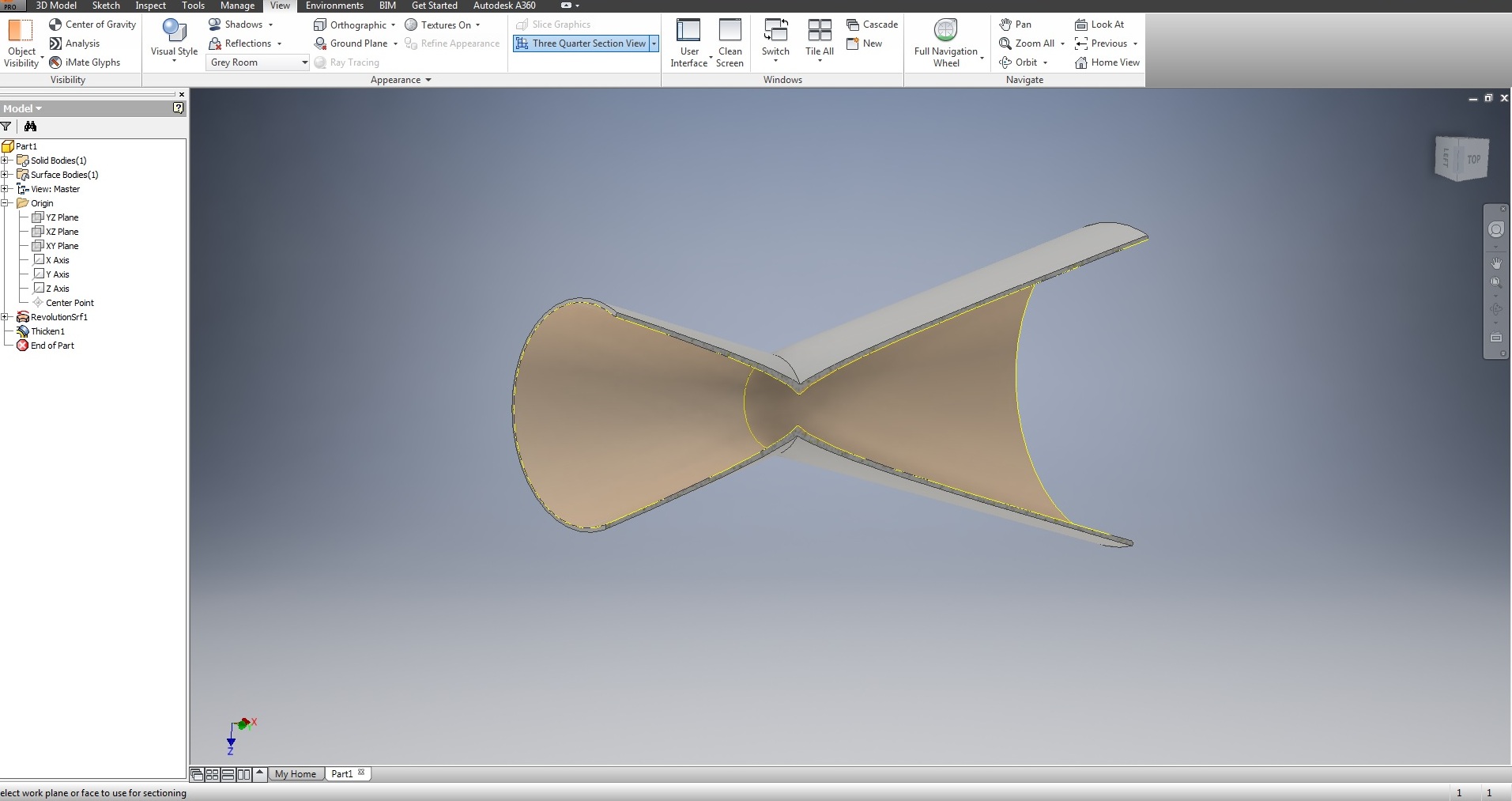
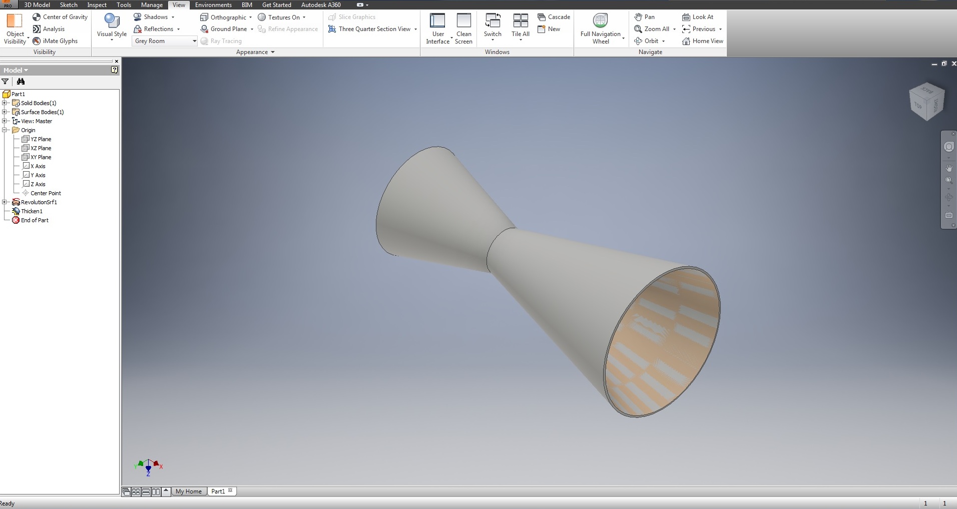
I have modelled a simple convergent divergent (CD nozzle) using Inventor software. Below first picture shows depicts
CD nozzle designed with sheet. In the second one, sheet is converted to model. The third
picture depicts the complete diagram of CD nozle.
 CD Nozzle Model [Download File]
NX software
NX, formerly known as NX Unigraphics or usually just UG, is an
advanced high-end CAD/CAM/CAE software package originally developed by Unigraphics, but since
2007 by Siemens PLM Software.
It is used, among other tasks, for:
Design (parametric and direct solid/surface modelling)
Engineering analysis (static; dynamic; electro-magnetic; thermal, using the finite element method; and fluid, using the finite volume method).
Manufacturing finished design by using included machining modules.
My final project enclosure was designed using NX software. This model can be exported as dxf/dwg file for mancining or laser cutting operation.
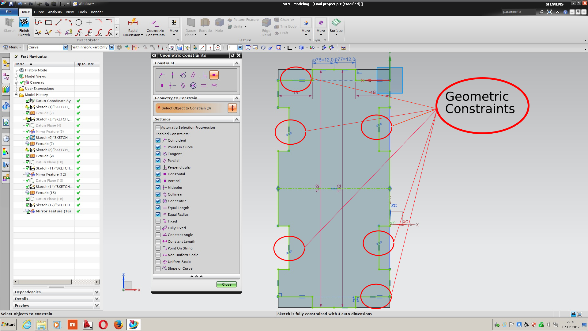
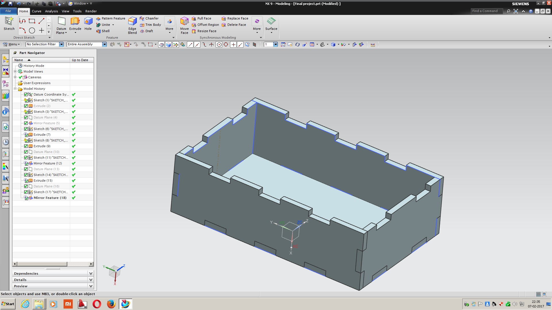 Project Enclosure [Download File]
Ansys
Ansys have engineering analysis software across a range of disciplines including finite element
analysis, structural analysis, computational fluid dynamics, explicit and implicit methods
and heat transfer analysis.
ANSYS Fluent, CFD, CFX, and related software are Computational Fluid Dynamics software tools used
by engineers for design and analysis. These tools can simulate fluid flows in a virtual environment
— for example, the fluid dynamics of ship hulls; gas turbine engines (including the compressors,
combustion chamber, turbines and afterburners); aircraft aerodynamics; pumps, fans, HVAC systems,
mixing vessels, hydrocyclones, vacuum cleaners, etc.
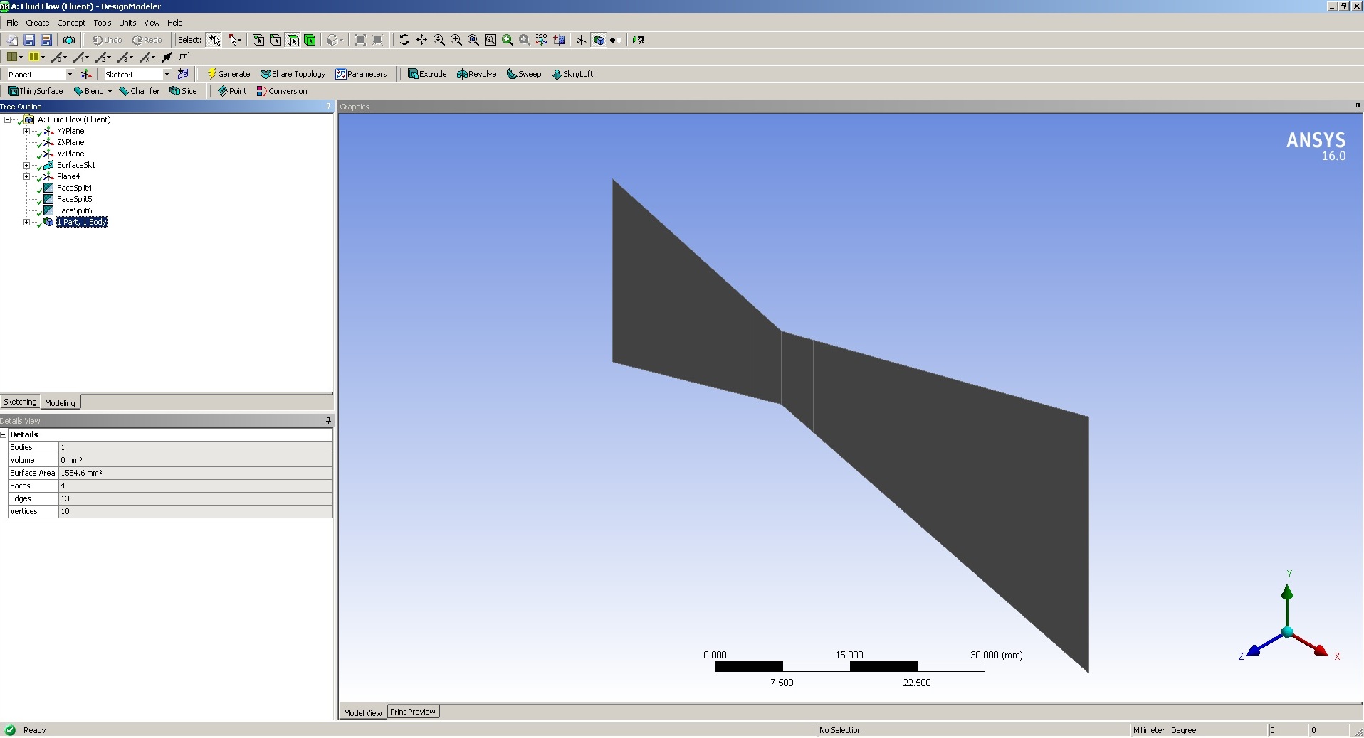
CFD Analysis
Computational fluid dynamics (CFD) is a branch of fluid mechanics that uses numerical analysis and data structures to solve and
analyze problems that involve fluid flows. The above model of a CD nozzle can be analysed with CFD.
A simple CFD analysis consists of the followoing process.
Design Modeller.
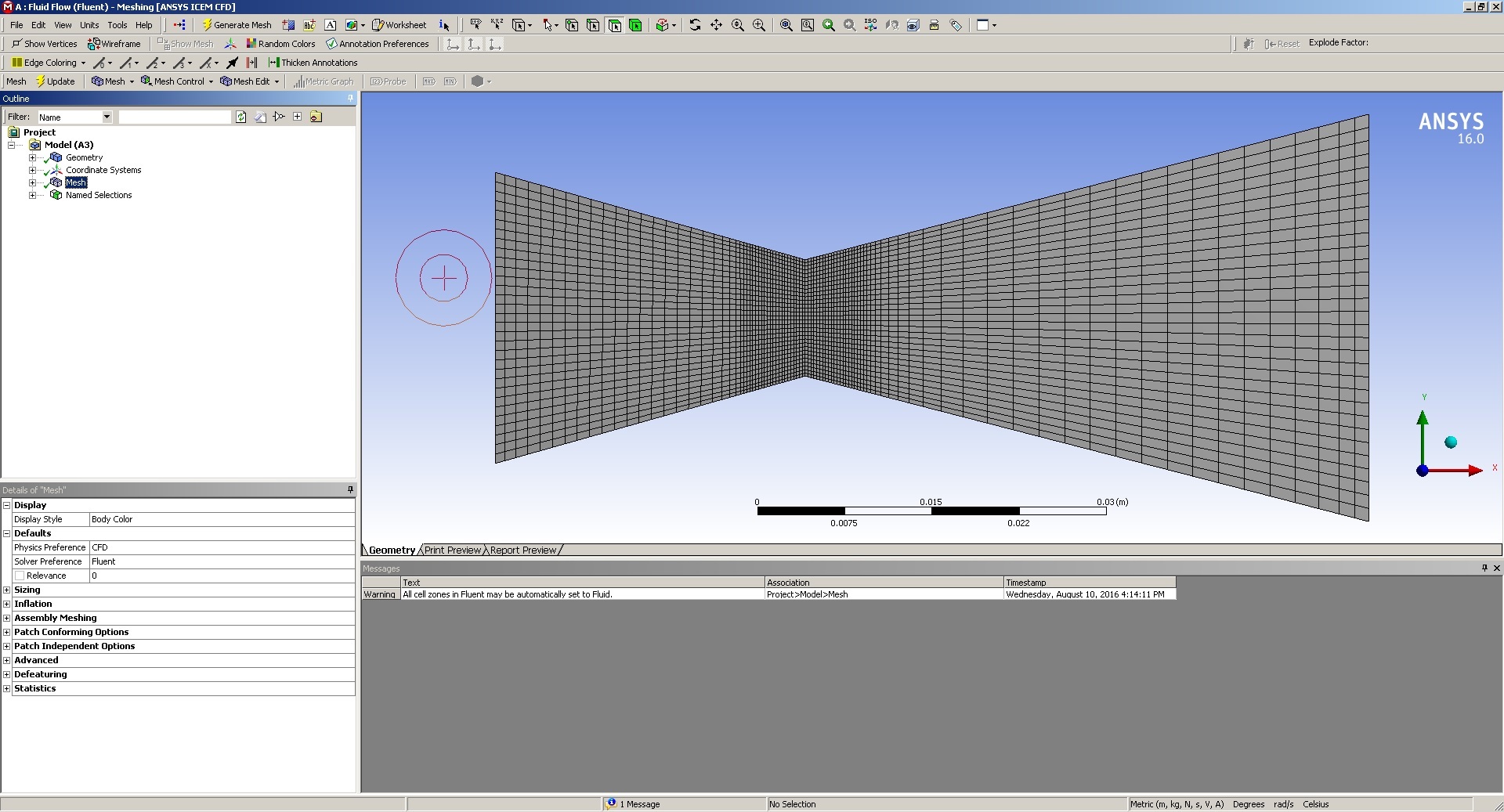
Meshing.
Setup.
Solution.
Post Processing.
A thin layer of the above model (CD nozzle) is considered for CFD anlysis. The outline of the model
is drawn using modeller followed by meshing.
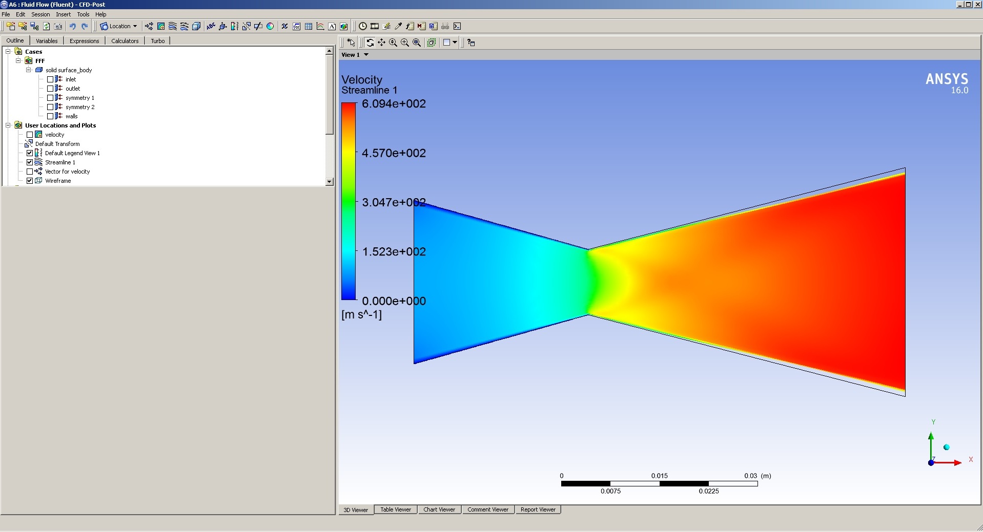
All the boundary conditions are verified in the setup and calculations are done.
The progression is monitored, the number of the iteration is set to 500. After the post processing
the gas velocity through the nozzle is shown below. The gas is chocked at the throat and is ejected
out at a supersonic velocity of 609m/s (indicated by red color). The 'mach diamond' is also visible
just after the throat.
 CD Nozzle [Download File]