"A composite consist of two or more different materials combined together to create a superior and unique material. This definition holds true for all composites, however, more recently the term "composite" describes reinforced plastics." In ancient times for construction applications, straw was mixed with mud to form a building material known as adobe. The straw provide the structural strength while the mud act as binder. Adobe structures are extremely durable in dry climates and carry their own weight into the foundation hence they posses compressive strength too.
Since the days of adobe, the use of composites has evolved to commonly incorporate a structural fiber and a plastic, this is known as Fiber Reinforced Plastics or FRP for short. Like straw, the fiber provides the structure and strength to the composite, while a plastic polymer holds the fiber together. Common types of fibers used in FRP composites include: Fiberglass, Carbon Fiber, Aramid Fiber, Boron Fiber, Basalt Fiber, Natural Fiber (Wood, Flax, Hemp, etc.). Common plastic resins used in composites include: Epoxy, Vinyl Ester, Polyester, Polyurethane, Polypropylene etc..
In everyday uses of fiber reinforced plastic composites include: Aircraft, Boats and marine, Sporting equipment(Golf shafts, tennis rackets, surfboards, hockey sticks, etc.), Automotive components, Wind turbine blades, Body armor, Building materials, Water pipes, Bridges, Tool handles, Ladder rails. The main advantage of composites are the lightweight properties, in addition to this, its Non-corrosive, Non-conductive, Flexible, will not dent, Low maintenance, Long life, Design flexibility.
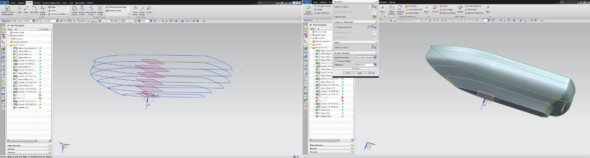
This week assigment is to create a composite material from 3D mould. I am planning to build a ship made up of Polystyrene. This mould act like a pattern while creating the composite. The design of the ship is done using NX. The overall size of the ship is around 0.55m in length, 0.25m in breadth and 0.125m in height. Each layers were generated using NX software. This can be easily done using copying curve from the previous layer followed by offset operation. Once after completing the 2D sketch, You can create mesh from curves. Initially it was a little difficult for me to create the exact shape, finally I managed to generate the shape without the help of any guids lines or points. The stl model was generated for milling operation. The design file and the model can be downloaded here.
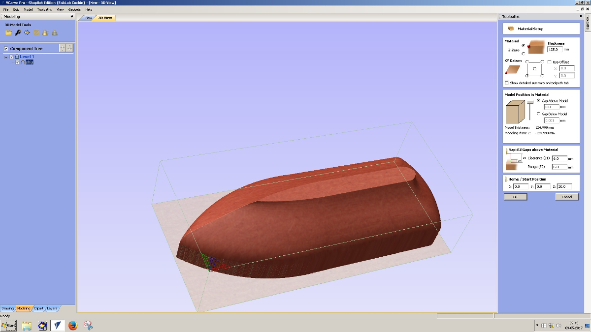
The stl model is exported to vcarv software. I have selected 1/2" tool for this operation since this may reduce the machining time. In final finish cutting operation, you may reduce the tool stepover to 20% attain a fine finish. After the simulation, gcode was generated and the same files can be downloaded here.
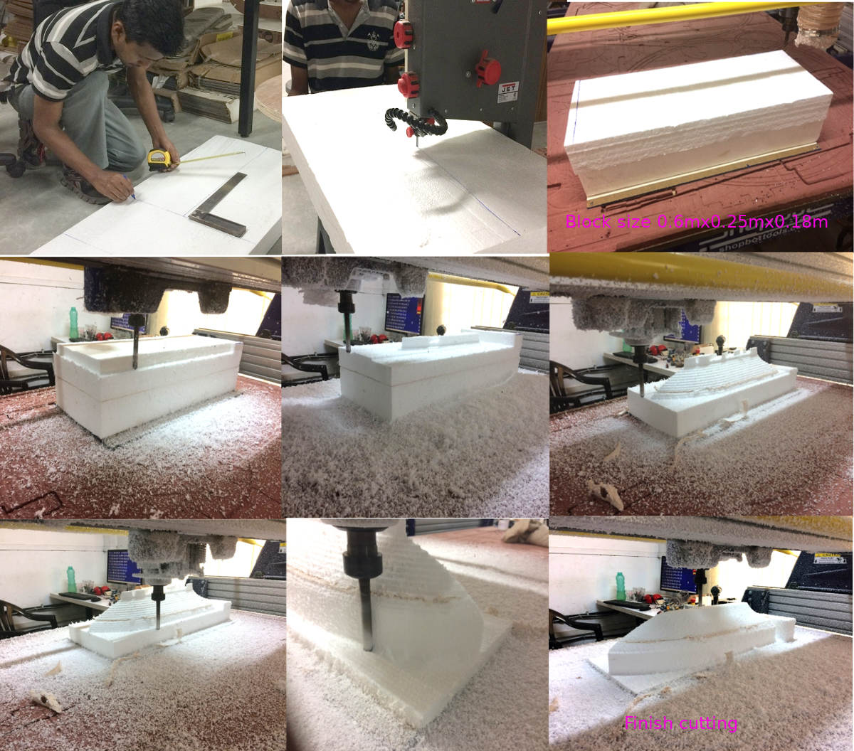
I have used 4" thickness polystyrene material for the pattern. Markings were done according to
requirement and cut using bandsaw machine. Set the machine tool to orgin. You may set the tool to
optimum Z value for large patterns. The Polystyrene blocks are stacked together. The overall block
size is 0.6mx0.25mx0.18m. Its not easy for the Polystyrene blocks to be held on machine bed directely, hence, I have used double sided tape to stick the Polystyrene block with acrylic sheet.
Then the same acrylic sheet is screwed to the machine bed firmly.
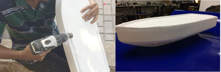
The video of final finish cutting on boat surface is show below. The 3D model is finished. The ship deck need to be shaped.
It will be difficult to hold polystyrene material of this shape on machine bed and may
consume more time. Hence I manually used a surfacing tool to reshape its deck.
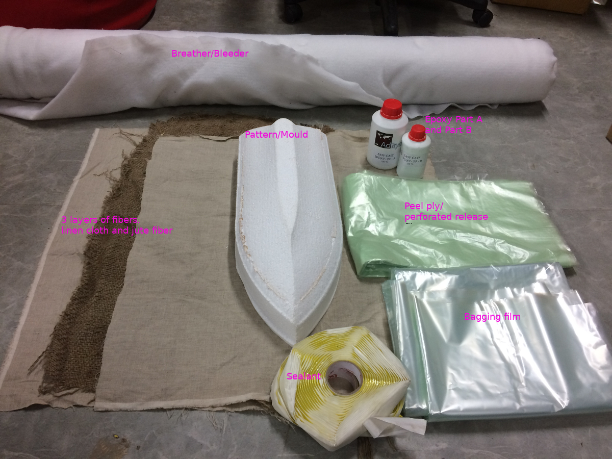
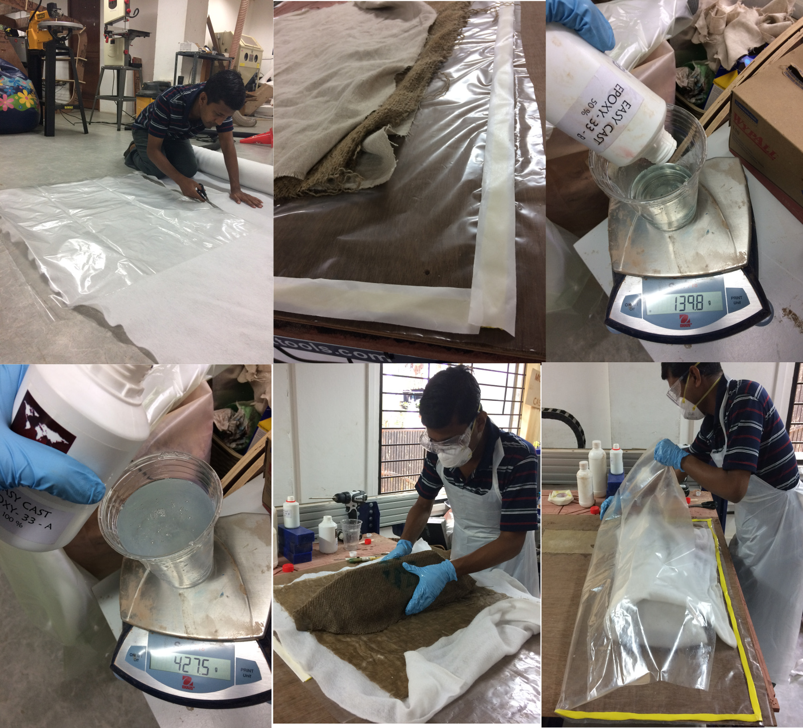
The breather material for the same is cut into pieces. I have used
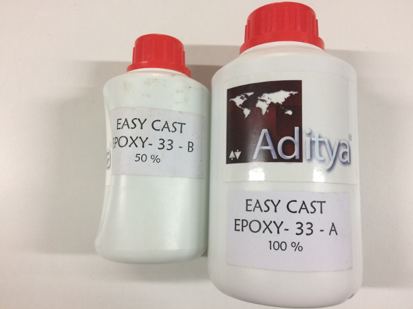
jute material covered by lines cloth on both sides. I have mixed 50% of the Epoxy-33-B to Epoxy-33-A
by weight after deducing the cup weight. The mixture is throughly mixed. The model of the ship is placed
on the bed upside down and the solution is applied onto the surface. Since the jute fiber is thick, the material
is socked with the solution before wrapping. The perforated release is applied onto the
body, this is done to squeeze excess solution from the fibers. These extra solution will be absorbed partially by
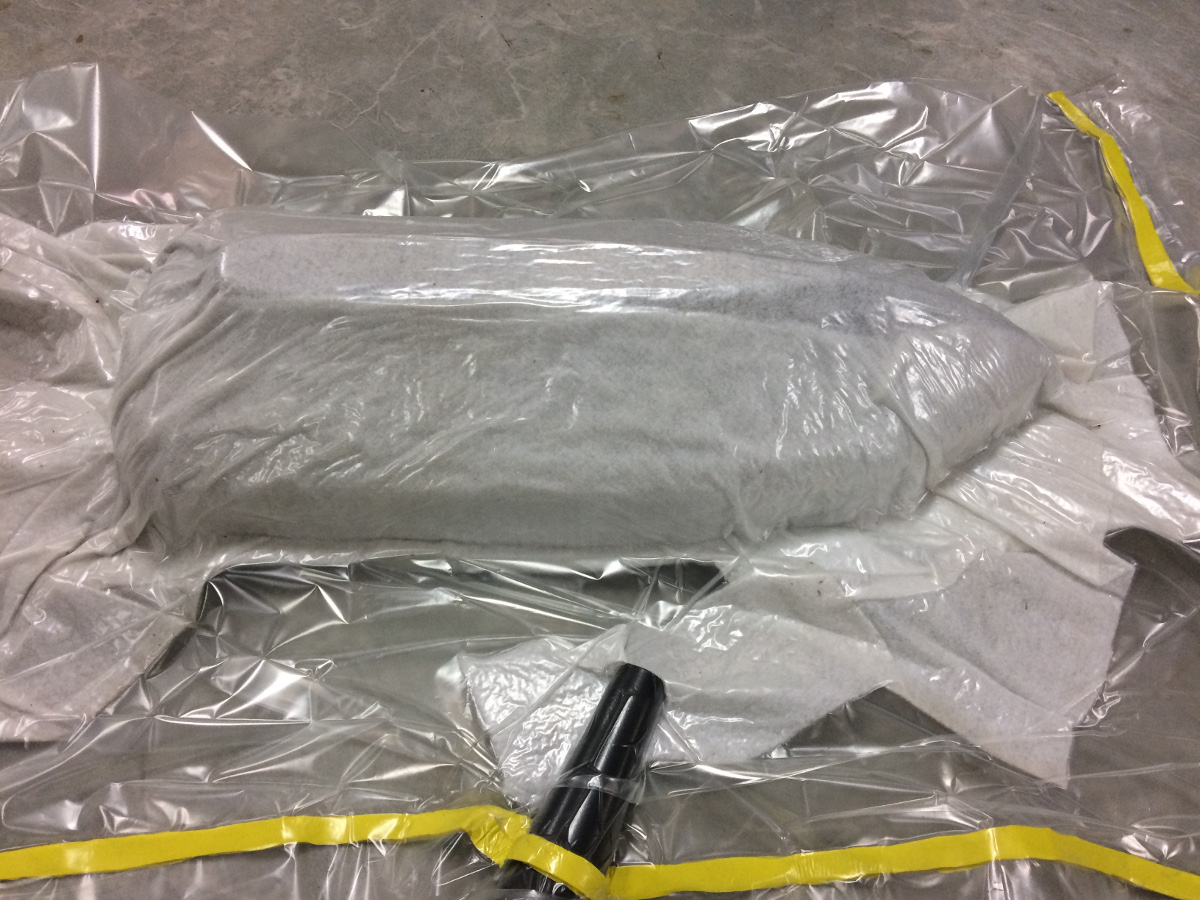
breather cloth. Sealant is applied onto the bagging film to ensure seal tight while vacuuming.
The breather cloth allow air to escape while vacuuming. Make sure the cloth extend
upto the vacuum pump nozzle to have a smooth air flow. Once the air is sucked out. Seal the inlet and keep the unit for 24 hrs.
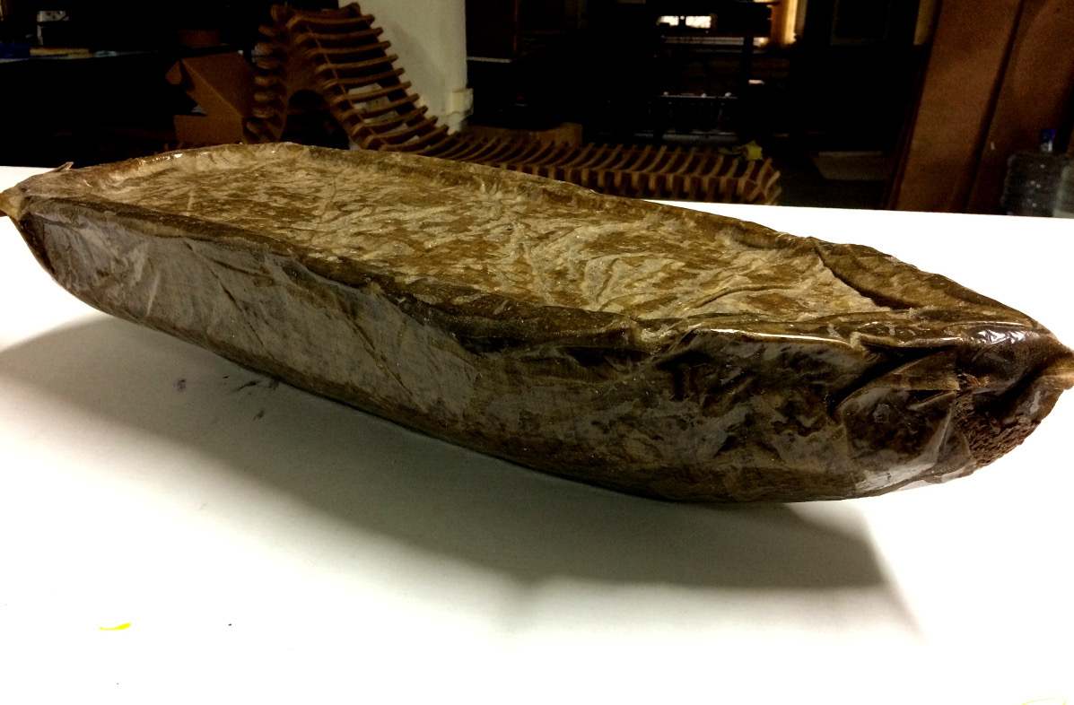
The final product is taken out after 24hrs and the picture is shown below. There are a few minor spots where the solution is not adequate,
those points can be filled with solution as a part of rework. Almost 98% of the area is perfect. I hope after minor rework, this unit is ready for ceremonial ship launching.
I would like to highlight some of the points.
Composite layup
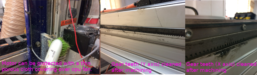
Safety
Materials
A typical layup setup for composite is shown below.
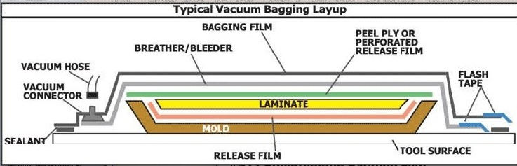
Mold:- Mold is used to place the layer in to obtain the desied shape. Mold can be created
using metals, composites, wood, plaster rubber etc. In our case its Polystyrene material.
Resins:- The resin act as the matrix of the composite to bind the material together
and handle the stress. In our case epoxy Part A and B is used. The corresponding figure is shown below. The ratio of Part A to B is 1:0.5.
The resin is to be mixed throughly, the mixture may get heated up during setting.
Use the mixture before its starts setting, use shallow vessel to avoid accidents due to uneven thermal expansion.
Reinforced fibers:- You amy use different fibers like glassfiber, chopped weaves, woven fabric,
carbon fiber, twill etc..
Sealant:- We are using vacuum sealant which act like a seal prevents air entrapping inside.
Breather/Bleeder layer:- The breather/bleeder layer is usually a non-woven synthetic
fiber material that comes in a variety of thicknesses. Its purpose is to provide a
continuous air path for pulling vacuum on the component. When the bag wrinkles against
the hard laminate, it traps air and the breather prevents this from happening.
The fabric will also absorb excess resin bleeding through the perforated release film.
As the bleeder has no release capability, a release film must be used against the component.
Releasing agent:-A releasing agent is applied on the composite part to easily remove from the
mold avoid stickingup. Release agent may be sprayed, brushed or wiped onto the surface.
Some common releasing agents are polyvinyl alcohol, wax, combination of wax and polymer etc.. In our case we dont require a releasing agent,
because we won't take the pattern will be a part of the composite structure and we won't take it out.
The composite layup parts are shown below.