This week assigment is to built an output device which can be motor, display or anything which which gives an output according to the instructions.
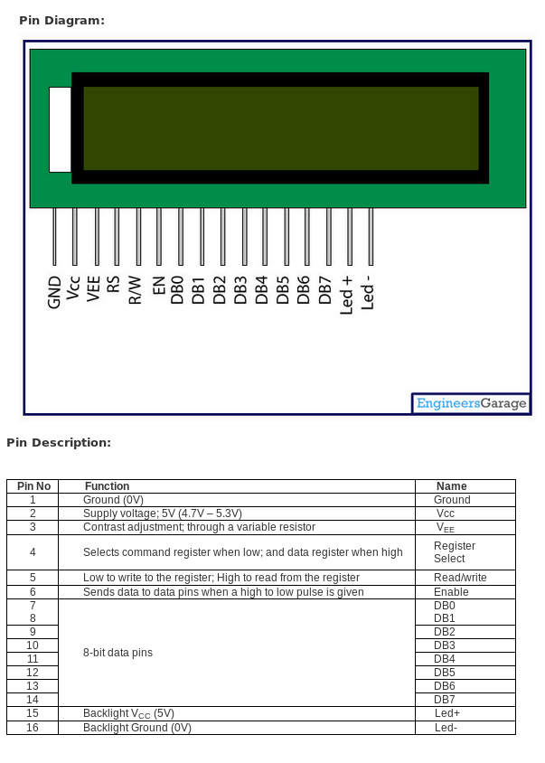
I have decided to make a device which display an output in 16x2 LCD display. I am planing to design with atmega 16, 44 TQFP (Thin Quad Flat Package). This chip have many input/output pins, so i could use the same in my future projects. Embedded programming is a new subject for me and I would like to learn and code new projects using the above PCB. I had gone through few tutorial pages to get an idea about 16x2 LCD. The pin diagram of LCD 16x2 is shown below.
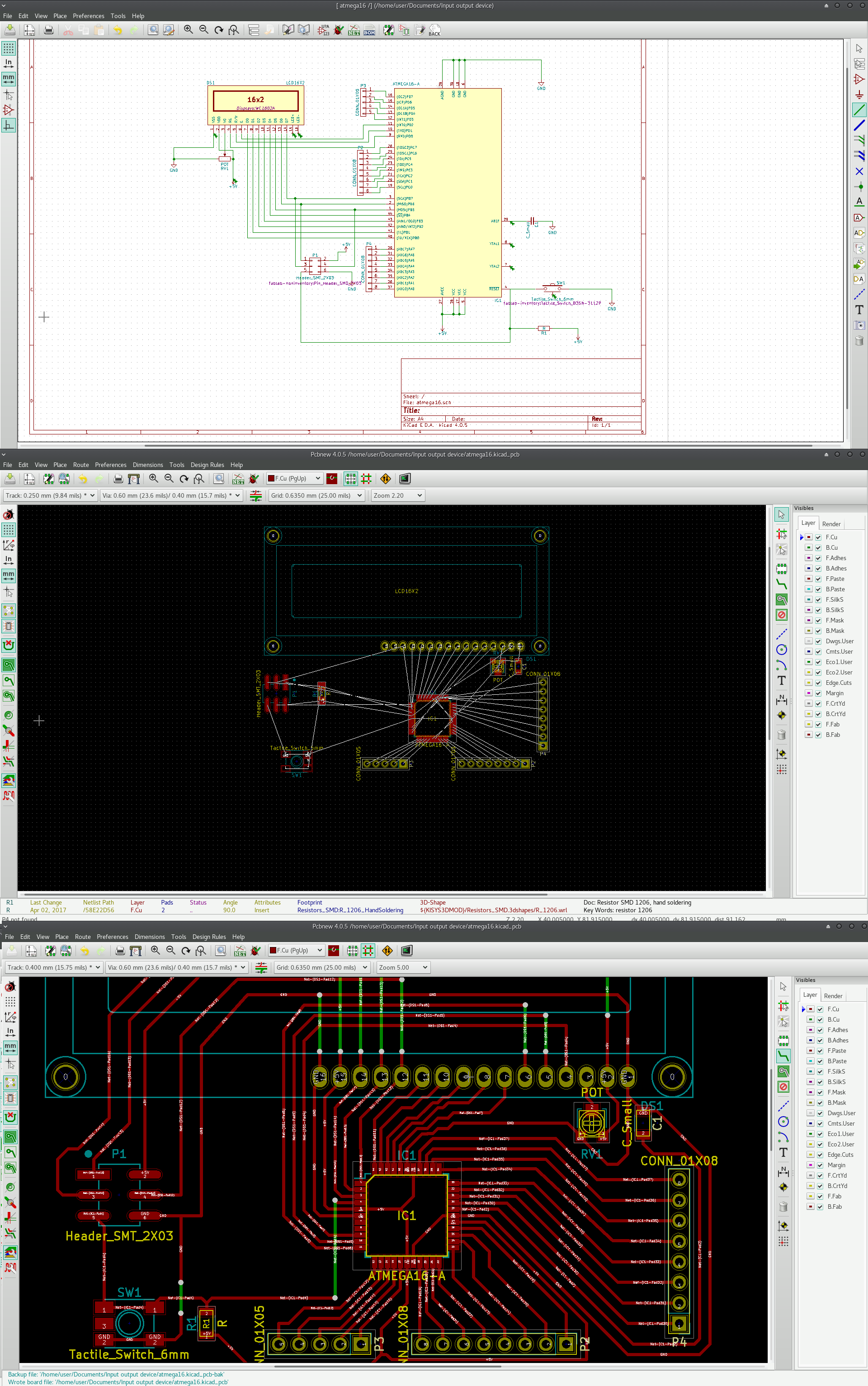
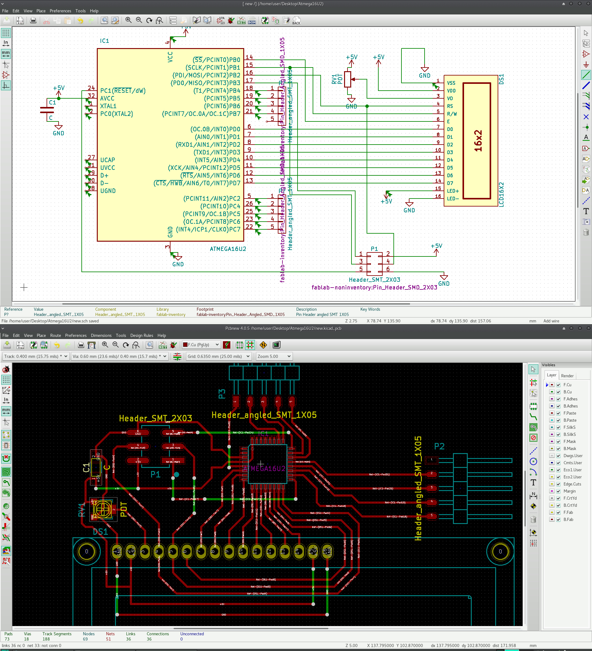
I have used Kicad for designing the PCB. The schematic diagram using Atmega 16 and its PCB is shown below. I have used entire Port B for LCD. Ports A, C and D can be used as input/output pins (more than 20 pins are available), hence this PCB can be utilised for many purpose due to the same reason. I have decided to use the internal clock thereby reduce the external components and it doesn't make apprectiable difference for our current projects. The 16X2 LCD with backlight has been configured with the microcontroller for 8-bit data transfer. The below figures shows PCB schematic diagram designed on Kicad software. Apart from the four major ports, a reset button and a resistor is connected to the reset pin. Atmega 16 have neumerous ports and all of them are powered seperately. While designing the PCB, I have used junction connector (shown in green color) to complete the PCB..
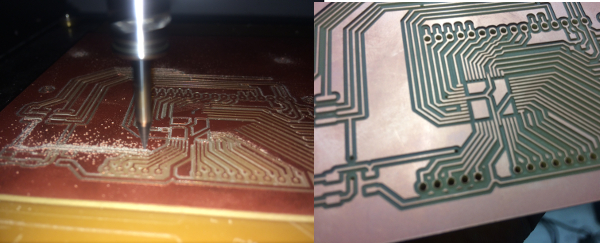
I have used 1/64" dia milling bit for the PCB milling process, but this milling bit was slightly bigger in size for 44 pin TQFP package. I don't want to try 1/100" miling bit since the PCB milling area seems to be more for this bit and soldering process would be very difficult. So, I have slightly reduced the current bit diameter to attain perfect tracks for the chip. The corresponding picture after milling process is given below.
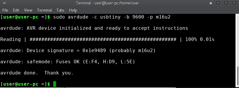
After assembling the unit, the TQFP package was not recognised. More over Atmega16U4 was not covered in avrdude program. I had spend more time surfing the internet to fix this out. After long hours, I decided to add this chip details to etc/avrdude.conf file.
AtMega16U4 is similar with atmega32u4, so I just copyed the 32u4 block in avrdude.config and made a 16u4 section with the signature bytes adjusted and rest remains same. The parameters to be changed are the following.
The above changes were added to the file, you can download it from here. After several attempt, I could not make it work, and the device was not detected by the program. Finally, figured out that the data sheet for the TQPF was different (I had used Atmega16 instead of Atmega16U4). "All my efforts were in vain". The mistake was irreparable, finally, I decided to desolder the major components from PCB. The chip was safely desoldered using desoldering pump and braid wire. The very next morning, I decided to make one more PCB with a new chip ATmega16U2 (supported by avrdude). Eventhough I added AtMega16U4 in config file, inspite of the advantage of having many ports, but lacks support with avrdude program and have some issues with setting the fuses. I decided to stick with ATMega16U2 for the sake.
AtMega16U2 is low-power Microchip 8-bit AVR RISC-based microcontroller combines 16KB ISP flash memory with read-while-write capabilities, 512B EEPROM, 512-Byte SRAM, 22 general purpose I/O lines etc.. The datasheet for the same can be downloaded here. I have decided to use the internal clock thereby reduce the external components and it doesn't make apprectiable difference for our current projects. The 16X2 LCD with backlight has been configured with the microcontroller for 8-bit data transfer. I have taken portC (5 pins) and portB (4 pins) for any futher application in future. The below figures shows PCB schematic diagram designed on Kicad software. The design files and png files for pcb milling can be downloaded here.
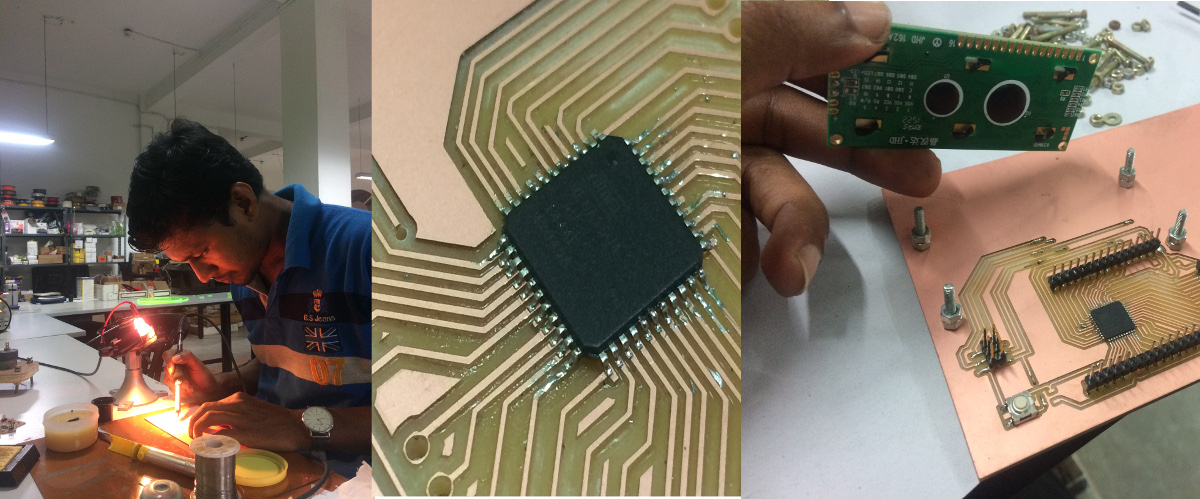
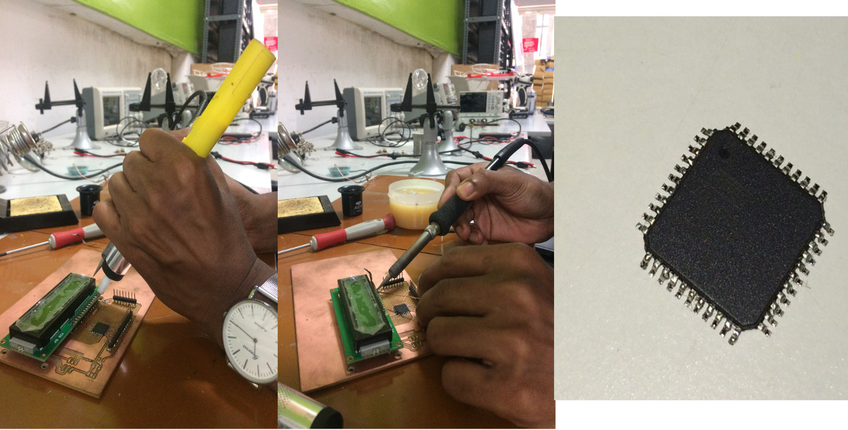
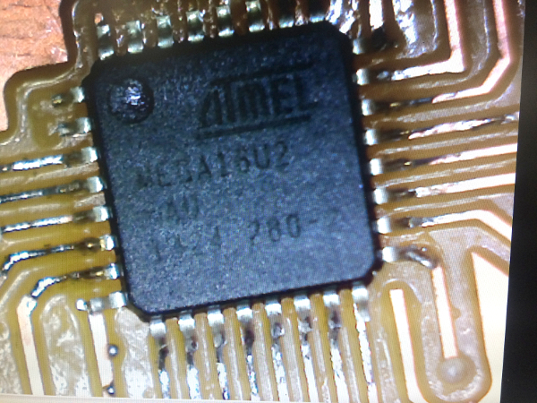
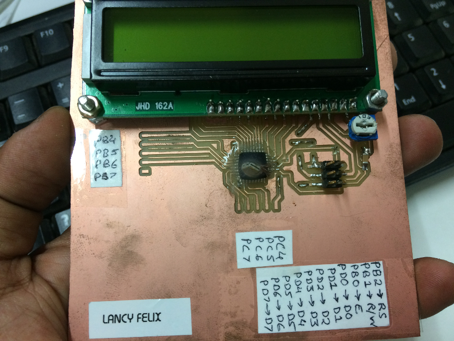
It took more time, but soldering flux helped me to achieve good soldering for the ATMega16U2 chip. The image is attached below.
Finally after soldering major components, the device was connected through ICSP connector. I was suprised that the device was not recognised by avrdude. I rechecked all the pins and data sheet, but everything was correct. After long hours of internet surfing, I figured out that ATMega16U2 wont start without an external oscillator eventhough it contain an internal oscillator. This is because, AtMega16U2 is an USB supported chip and such chip expect an external oscillator. You can start a chip using external oscillator and program (fuse) it to use internal oscillator but, while flashing the next program, the device resets to default settings expecting an external oscillator. This forced me to connect an external oscillator to my circuit, I soldered an 8Mhz crystal across the terminals to wakeup the chip and checked with avrdude command. The device was recognised now.
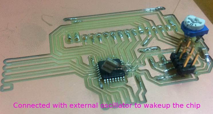
Once the device was recognised, rest of the components were soldered in its place. I glued the external oscillator with the chip. Marked all the available ports.
It took me many hours to figure out a few changes in the program, however after many attempts, I got some output in LCD display with unrecognised characters. In the very next day after a long hours of web surfing, I could alter a few codes thereby correcting the unrecognised characters.
AVR GCC is the backend engine for Arduino IDE software. So, its better to learn AVR GCC program, more over the C code covers more details as compared to c++ by Arduino IDE. I think a good approach is to concentrate on the core C functionality. The program for displaying 'hello world' in 16x2 LCD is given below.
Embedded C program can be easily flashed using four commands mentioned below. All the files can be downloaded here.#include <avr/io.h> #define F_CPU 16000000L #include <util/delay.h> #define lcd_data PORTD //LCD data port #define control PORTB #define en PB0 // enable signal #define rw PB1 // read/write signal #define rs PB2 // register select signal void lcd_init (void); void lcd_command(unsigned char cmd); void lcd_write(unsigned char data); void lcd_string(unsigned char *str); void dis_cmd(char cmd_value); void dis_write(unsigned char data); int main() { DDRD = 0xFF; DDRB = 0xFF; lcd_init(); _delay_ms(50); _delay_ms(1); lcd_str("Hello world"); _delay_ms(50); dis_cmd(0xc0); lcd_str("Lancy Felix"); return 0; } void lcd_init (void) { dis_cmd(0x02); //initialises lcd on 4 bits mode _delay_ms(1); dis_cmd(0x28); //initialises lcd to use 2 line and 5*7 matrix ie 16*2 lcd on 8 bits _delay_ms(1); dis_cmd(0x01);//clears lcd screen _delay_ms(1); dis_cmd(0x0E);//display ON cursor ON _delay_ms(1); dis_cmd(0x80);//cursor is set on the 1st line _delay_ms(1); return; } void lcd_command(unsigned char cmd) { lcd_data =cmd; control = (0<<rs)| (0<<rw) | (1<<en); // setting rs to 0 is command mode when rw=0 write mode _delay_ms(1); control = (0<<rs)| (0<<rw) | (0<<en); _delay_ms(50); // 2ta control command is used for the high to low transition of enable as the code works on the falling // edge of the enable en return; } void lcd_write(unsigned char data) { lcd_data= data; control = (1<<rs)| (0<<rw) | (1<<en); // setting rs to 0 is command mode when rw=0 write mode _delay_ms(1); control = (1<<rs)| (0<<rw) | (0<<en); _delay_ms(50); return; } void dis_write(unsigned char data) { char data1; data1 = data & 0xF0; //mask lower nibble because PA4-PA7 pins are used. lcd_write(data1); data1 = ((data<<4) & 0xF0); //shift 4-bit and mask lcd_write(data1); return; // send to LCD } void lcd_str(unsigned char *str) { int i = 0; while(str[i] != '\0') { dis_write(str[i]); i++; } return; } void dis_cmd(char cmd_value) { char cmd_value1; cmd_value1 = cmd_value & 0xF0; //mask lower nibble because PB4-PA7 pins are used. lcd_command(cmd_value1); // send to LCD cmd_value1 = ((cmd_value<<4) & 0xF0); //shift 4-bit and mask lcd_command(cmd_value1); // send to LCD }
   avr-gcc -g -Os -mmcu=atmega16u2 -c lcd.c
   avr-gcc -g -mmcu=atmega16u2 -o lcd.elf lcd.o
   avr-objcopy -j .text -j .data -O ihex lcd.elf lcd.hex
   sudo avrdude -c usbtiny -p atmega16u2 -U flash:w:lcd.hex