This is one of my interesting project and the same which i dont want to go through. I have made a few professional audio amplifiers myself for my personal use.
I havn't tried a full audio band audio spectrum analyser due to complexity of codes.
I am from Mechanical Engineering background and not familiar with programming codes. I know its
very hard for me to learn Fast Fourier Transform codes which uses digital signal processing techniques, still
i need a compact spectrum analyser, and i am trying to make one.
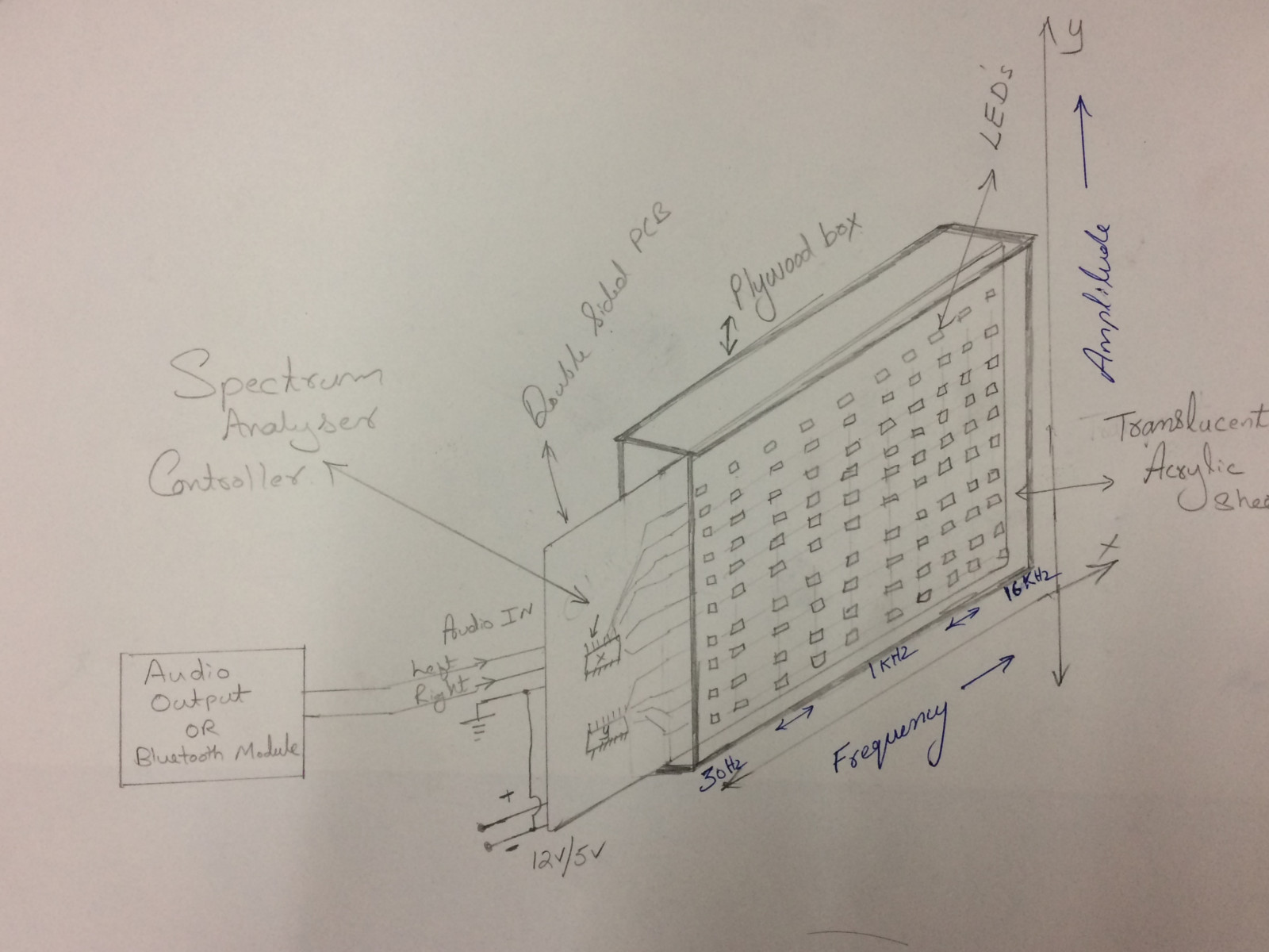
The spectrum analyser measures the input signal magnitude verses frequency in the audio range (20hz to 20Khz), in 10 bands.
A spectrum analyzer looks like an oscilloscope and, in fact, some lab instruments can function either as an oscilloscope or a spectrum analyzer.
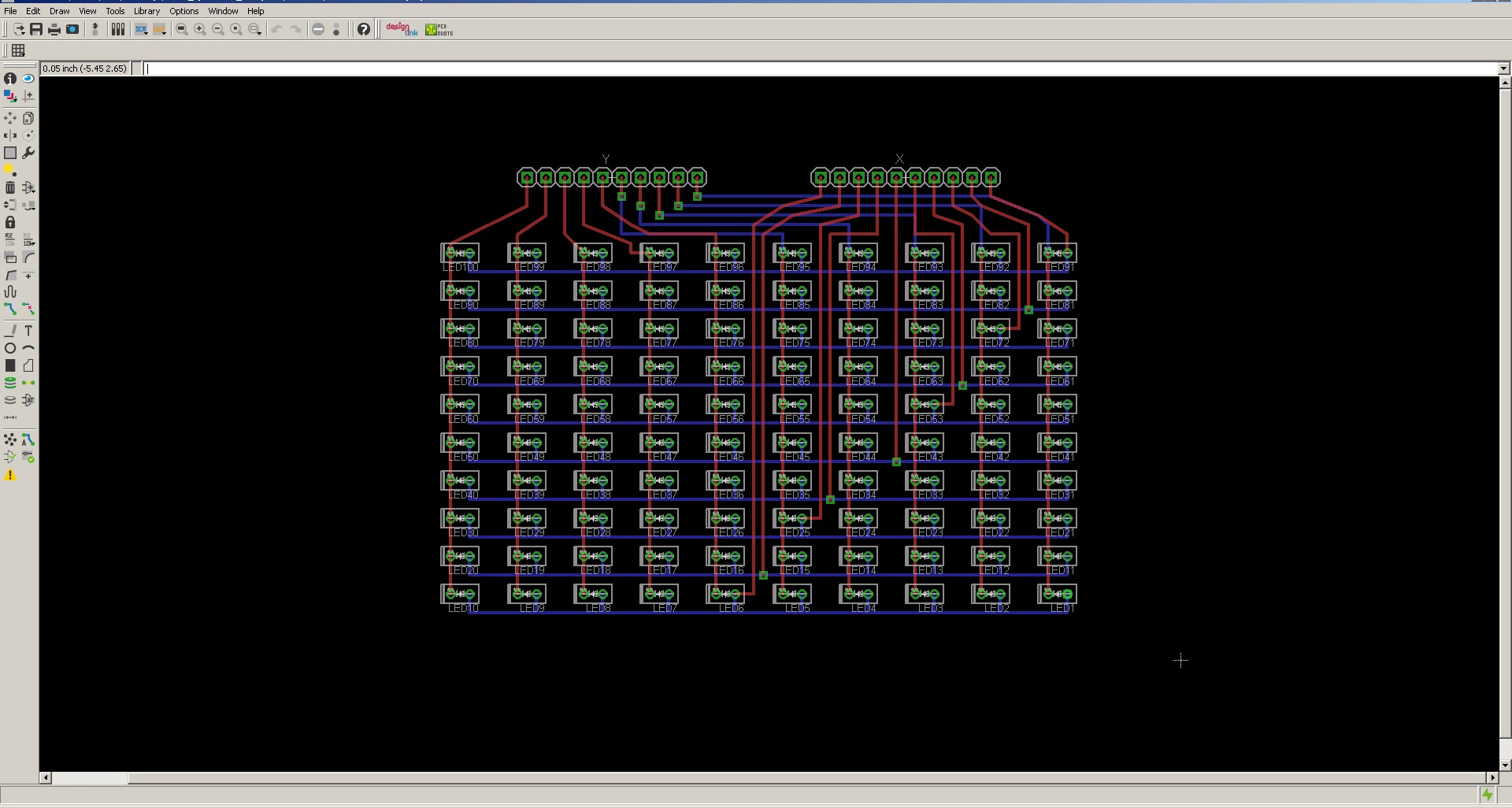
The schematic circuit of LED is plotted on Eagle software. EAGLE stands for Easily Applicable Graphical Layout Editor.
EAGLE is a scriptable electronic design automation application with schematic capture, printed circuit board layout, auto-router.
There are 100 LED's in the PCB. controlled by 20 wires,each LED can be lit individually if required.
The only possible way to accommodate 100 LED's in a small area is to design a double sided PCB board.
I have designed both sides (Top and Bottom Layer) of the PCB, and is shown below. The Top and Bottom layers can be
turned on and off by clicking the Layer button. The tracks can be exported by clicking FILE>EXPORT>IMAGE.
The image is saved as png format with a resolution of 600DPI. These picture can be exported to milling machine later.
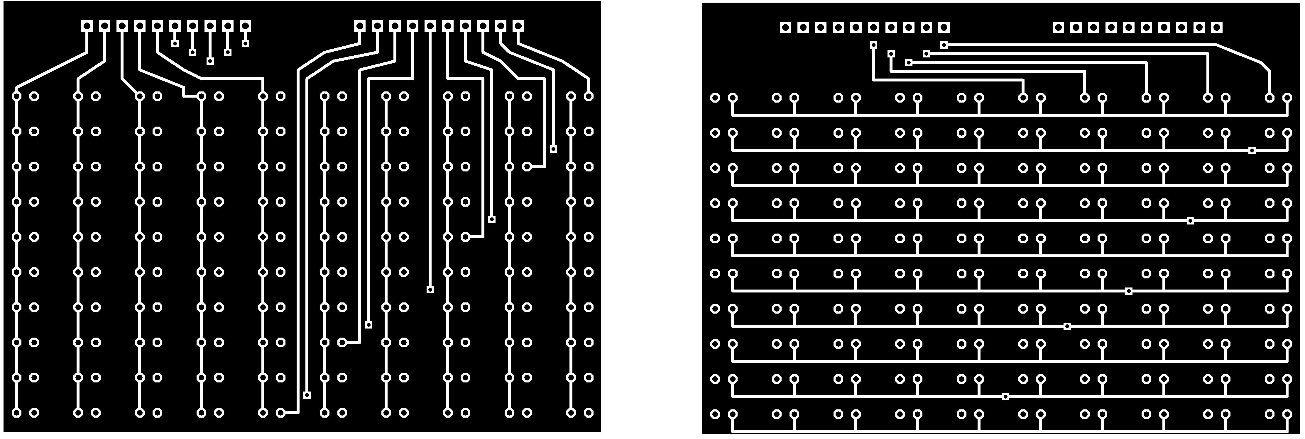
The merged Top and bottom layer of the PCB with LED's is shown below. The connectors X and Y is shown in the schematic. Electrical signal need to be transfered between top and bottom layers. Both tracks are to be soldered with wire/connector at 15 different locations. SMD LED doesn't have legs and cannot be used in this circuit, hence tiny rectangular LED (with two pins) is opted for this purpose.
The designed PCB size for this display system is 13cmx11cm only. 100 Led's need to be incorporated in this small area. Modella milling machine is used for milling operation. I have tried to mill double sided PCB twice, but in vain. The PCB tracks on both sides doesnt match exactely. So, I have used two single sided PCB connected back to back through LED legs. After milling operation, I have cleaned the copper surface and applied soldering flux. Once all the LED is soldered, it would be difficult to resolder any pins. Hence special care should be taken while soldering each LED. I have applied solder on all main tracks to avoid resolder in future. I started to solder each LED from one corner. I have used one reference plate to hold one row of LED at a defined height while soldering.
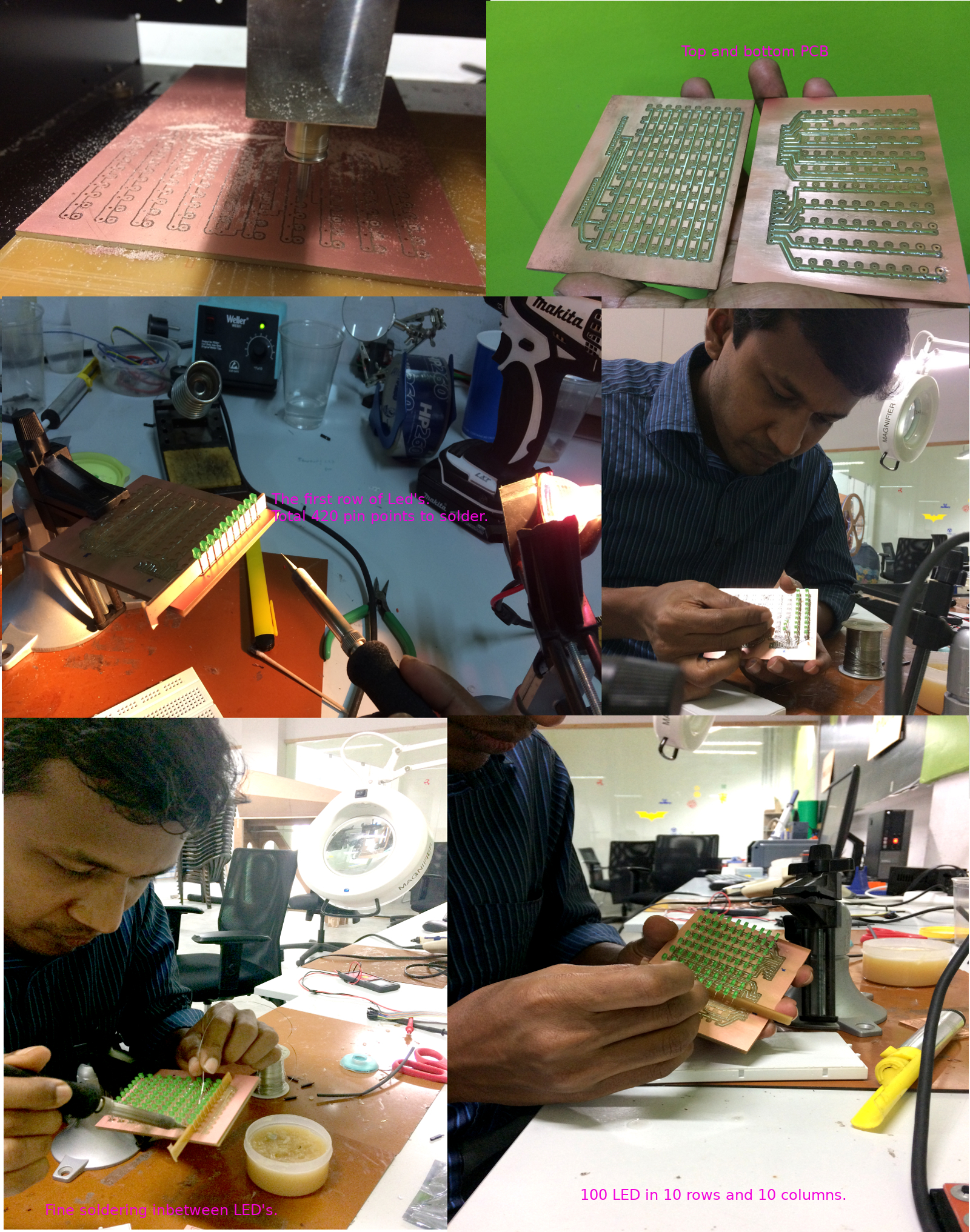
Once after soldering, each LED can be checked by connecting its corresponding X and Y connector to 2.8v supply. I have checked all the 100 Led's and all were working. The same video is shown below.
The LM4861 is a bridge-connected audio power amplifier capable of delivering 1.1W of continuous average power to an 8Ω load with 1% total harmonic distortion (THD) using a 5V power supply. Audio power amplifiers were designed specifically to provide high quality output power with a minimal amount of external components using surface mount packaging. Since the LM4861 does not require much components, it is optimally suited for low-power portable systems. The simple schematic diagram of amplifier and its frequency response curve is shown below.
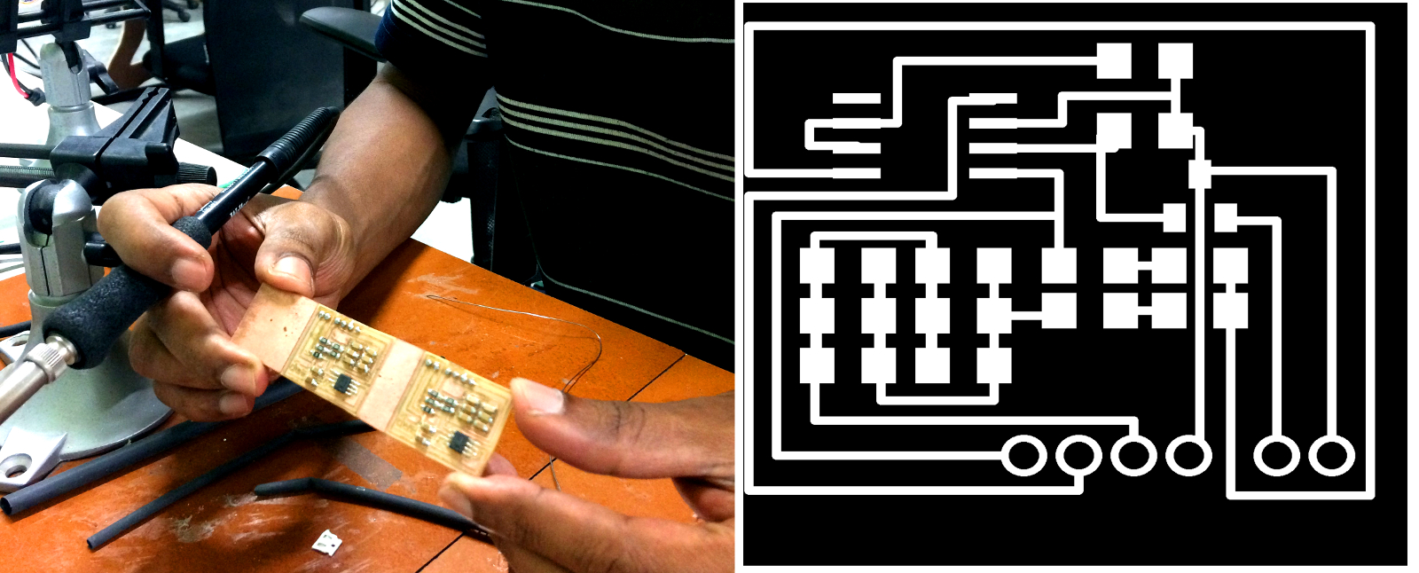
The amplifier design was done in eagle software. The input supply for the amplifier is just 5v and can be easily powered from computer USB port/mobile charger. The schematic circuit and PCB design is shown below.
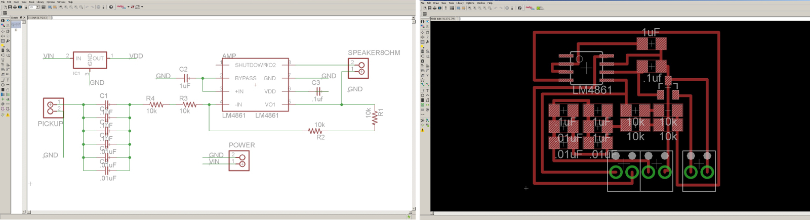
The overall size of the amplifier is 2.5cmx3cm. I had incorporated left and right channel (stereo) on a small PCB and milled using Rolland PCB router. All components were soldered and the amplifier was tested and found to be working fine.
The Matrix display board is connected to arduino for testing. The code for checking audio strength is refered from internet and is shown below. This code is for a single band spectrum with 10 channels.
#define N_PIXELS  10  // Number of LEDs
#define MIC_PIN   A0  // Input is attached to this analog pin
#define DC_OFFSET  0  // DC offset in mic signal - if unusure, leave 0
#define NOISE     0  // Noise/hum/interference in signal
#define SAMPLES   40  // Length of buffer for dynamic level adjustment
#define TOP       (N_PIXELS + 2) // Allow dot to go slightly off scale
#define PEAK_FALL 1000  // Rate of peak falling dot
const int led[] = {2,3,4,6,7,8,9,10,11,12};
byte
peak      = 0,      // Used for falling dot
dotCount  = 0,      // Frame counter for delaying dot-falling speed
volCount  = 0;      // Frame counter for storing past volume data
int
vol[SAMPLES],       // Collection of prior volume samples
lvl       = 10,      // Current "dampened" audio level
minLvlAvg = 0,      // For dynamic adjustment of graph low & high
maxLvlAvg = 512;

void setup() {
  analogReference(EXTERNAL);
  memset(vol, 0, sizeof(vol));
  for(int i=0; i<N_PIXELS; i++)
  {
    pinMode(led[i],OUTPUT);
  }
}

void loop()
{
  uint8_t  i;
  uint16_t minLvl, maxLvl;
  int n, height;
  n   = analogRead(MIC_PIN); // Raw reading from mic
  n   = abs(n - 512 - DC_OFFSET); // Center on zero
  n   = (n <= NOISE) ? 0 : (n - NOISE);     // Remove noise/hum
  lvl = ((lvl * 7) + n) >> 3;    // "Dampened" reading

  // Calculate bar height based on dynamic min/max levels (fixed point):
  height = TOP * (lvl - minLvlAvg) / (long)(maxLvlAvg - minLvlAvg);

  if(height < 0L) height = 0; // Clip output
  else if(height > TOP) height = TOP;
  if(height > peak) peak = height; // Keep 'peak' dot at top

  for(i=0; i<N_PIXELS; i++)
  {
    if(i < height)
    {
      digitalWrite(led[i], LOW);
    }
    else
    {
      digitalWrite(led[i], HIGH);
    }
  }
  if(peak > 0 && peak <= N_PIXELS-1)
  {
    // colour peak dot
  }
  if(++dotCount >= PEAK_FALL) { //fall rate

    if(peak > 0) peak--;
    dotCount = 0;
  }
  vol[volCount] = n;   // Save sample for dynamic leveling
  if(++volCount >= SAMPLES) volCount = 0; // Advance/rollover sample counter
  // Get volume range of prior frames
  minLvl = maxLvl = vol[0];
  for(i=1; i<SAMPLES; i++) {
    if(vol[i] < minLvl) minLvl = vol[i];
    else if(vol[i] > maxLvl) maxLvl = vol[i];
  }
  if((maxLvl - minLvl) < TOP) maxLvl = minLvl + TOP;
  minLvlAvg = (minLvlAvg * 63 + minLvl) >> 6; // Dampen min/max levels
  maxLvlAvg = (maxLvlAvg * 63 + maxLvl) >> 6; // (fake rolling average)
}
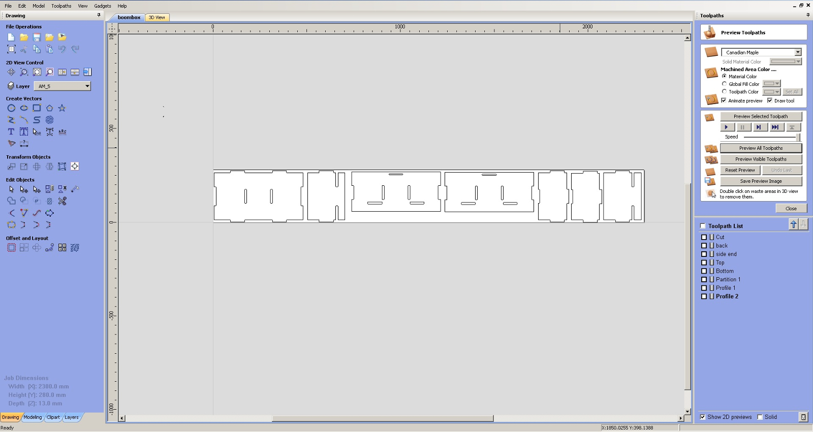
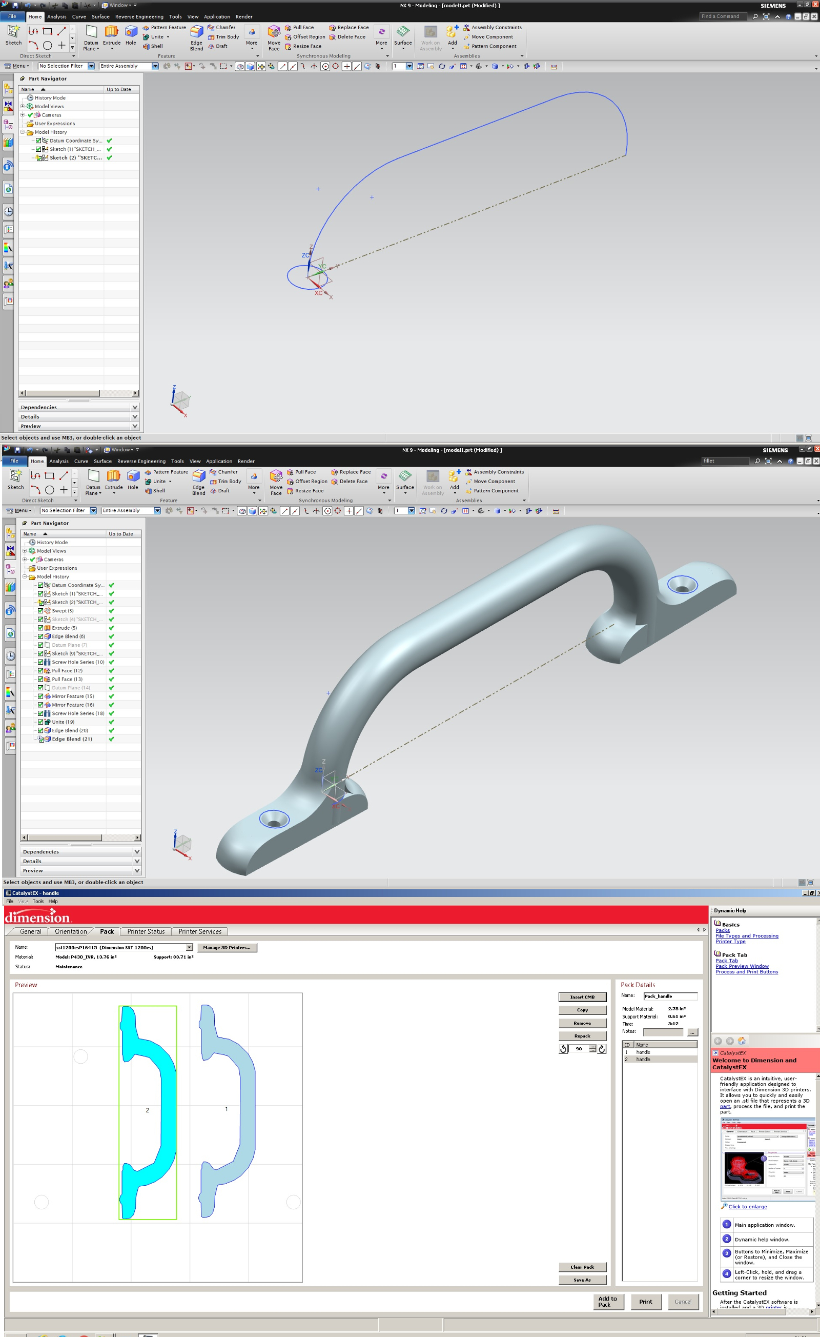
The enclosure for the unit can be realised from plywood having a thickness of 12mm. The design of the same has been done using NX software. The final dxf file has been exported to autocad for the CNC machining. The design files for the same can be downloaded here.
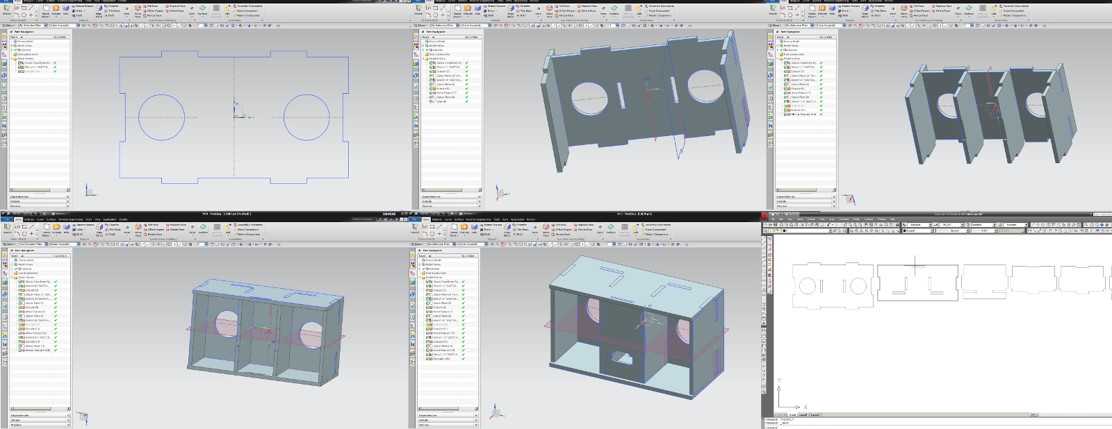
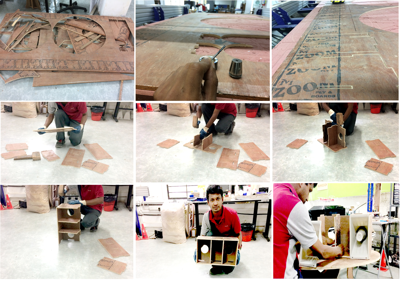
The size of the enclosure is 50cmx25cmx30cm. This enclosure contains seven wooden pieces and can be realised from scrap material. The available scrap pieces in FabLab is shown in below picture. I have opted 1/8" milling bit so as to avoid big tool radius compensation while cutting. The plywood has been screwed to the base surface. The tool feed is kept at slow pace (0.5inch/s) to attain a better side finish. The machining operation is tabulated in Vcarv software and the shopbot gcode is exported from the same and can be downloaded here.
After milling operation, each pieces is taken out and removed the burr edges using sandpaper measuring 80-grit. Gloves is recommended while burr removing. All the pieces can be assembled easily one by one starting from the back plate. The two holes provided at the black plate is for mounting horn speakers. Horn speaker may sit onto the slots and can be tighteen up using its cover itself. This technique will save extra fittings and make the overall design simple. The schematic and the PCB circuit can be downloaded from here.
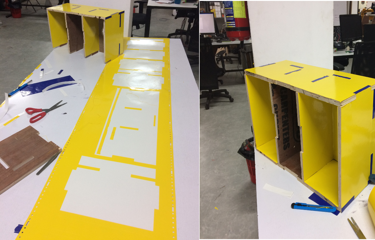
The front panel of the unit is realised from acrylic sheet of thickness 6mm. I have opted translucent orange sheet, which is permeable to green LED light. The sheet contains a few engraving for AUX input and 5v DC terminals.
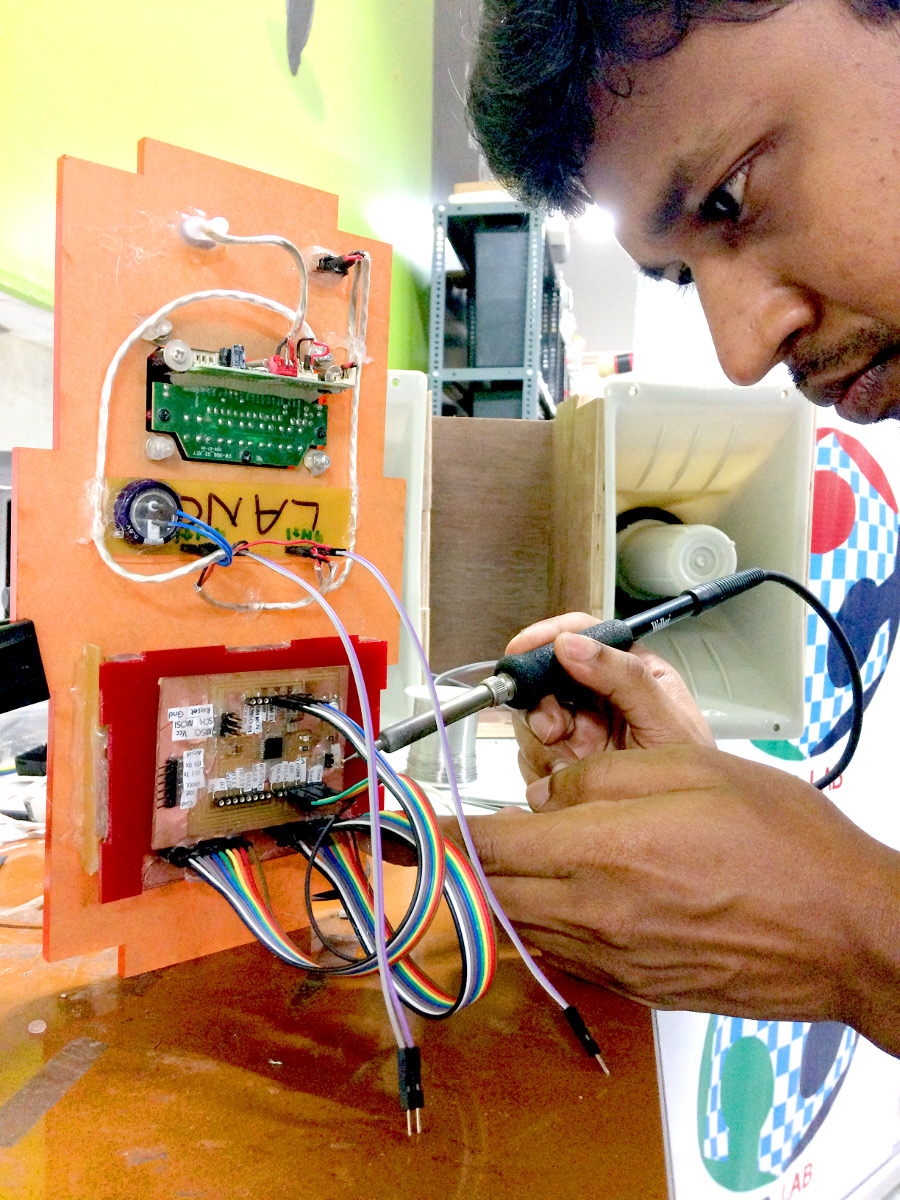
All the electronic parts were cleaned and were ready for assembly. This product is intended to run for another 20 year without any appreciable errors. For these kind of audio project, special two core shielded wires were used to eliminate the noise from surroundings. All the terminals were soldered in the exact locations followed by insrting protective sleeves to prevent short circuit and distrotion due to dust and other impurities in the audio lines. A 1000uF capacitor was inserted onto the 5v supply terminal to reduce the ripples from DC adapters. Apart from matrix disply, the USB mp3 module (boughtout item) is equipped with AUX input, stereo FM and IR remote control (7m range).
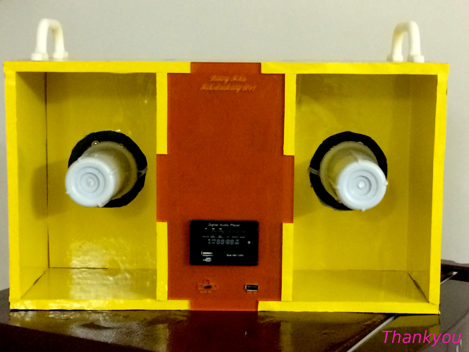
The front panel along with the corn speakers were assembled and the unit is tested with an USB loaded with mp3 files. A 5v input supply is driven from portable USB battery charger. One of the main reason for choosing a horn speaker is because, this is available abundant in our FabLAb now it can produce loud voice for a fraction of power. The main audible mid frequency lies in the range 200Hz to 1000Hz, this is where the horn speaker produce maximum decibel. I have removed the horn from the horn speaker to attain a clear voice. The reflected sound waves from the diaphram bounce back to the inner box creating a pleasant audible frequency. These mid range frequency is best suited for hearing news channels, where the audio mid range voice is more important. The testing video is shown below. (Note:-The audio/mp3 song has been muted to avoid copyright issue)
I am longing for a 10 band spectrum analyser for the last 15 years, the above finished project is limited to a single band. The main reason for this is due to the complex Embedded program with Fast Fourier Transform (FFT). Many of these programs are still under reaserch. I am purely from a mechanical background and a program like this is beyond my limits. Hence, I figured out an alternative solution. The real 10 bands ranging from 30Hz to 16Khz range can be realised with analog circuits. The analog circuit for the same is complex, but the bargraph produced by these analog circuits are alive with the sound and seems dancing with the music.
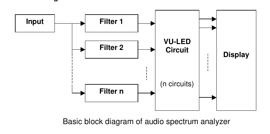
Each filters are designed for a particular frequency. Band pass filters are used for this purpose, which pass the belonged fixed frequency and removes the rest. This can be designed with the help of capacitors, resistors and transistors/OP-AMP. The matrix display 10x10 band can be used here for the display. The X rows of these LED's were connected with the output from 10 bandpass filters driven by power transistors. The Y row of the LED is connected to LM 3914 chip. LM 3914 IC visually show the magnitude of an analog signal and can drive upto 10 LED. This IC was introduced by National Semiconductor in 1980 and is still available.
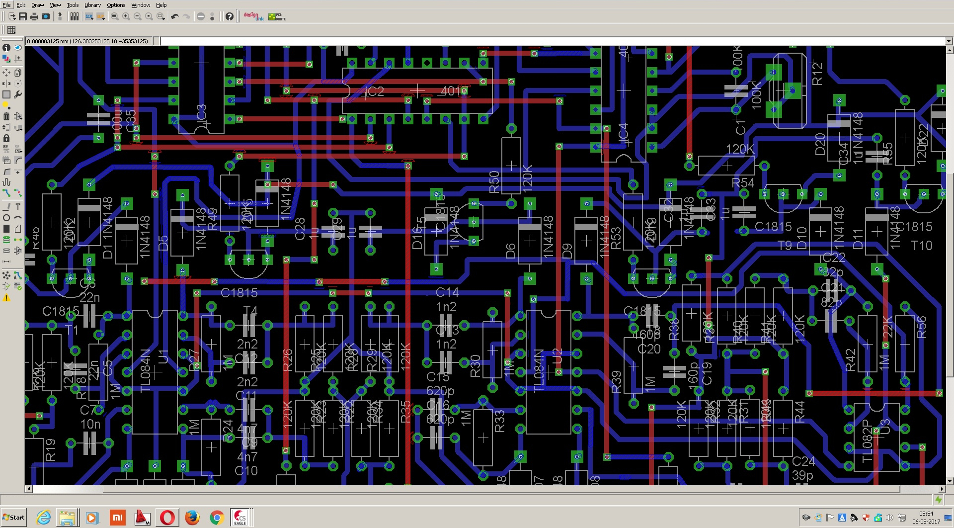
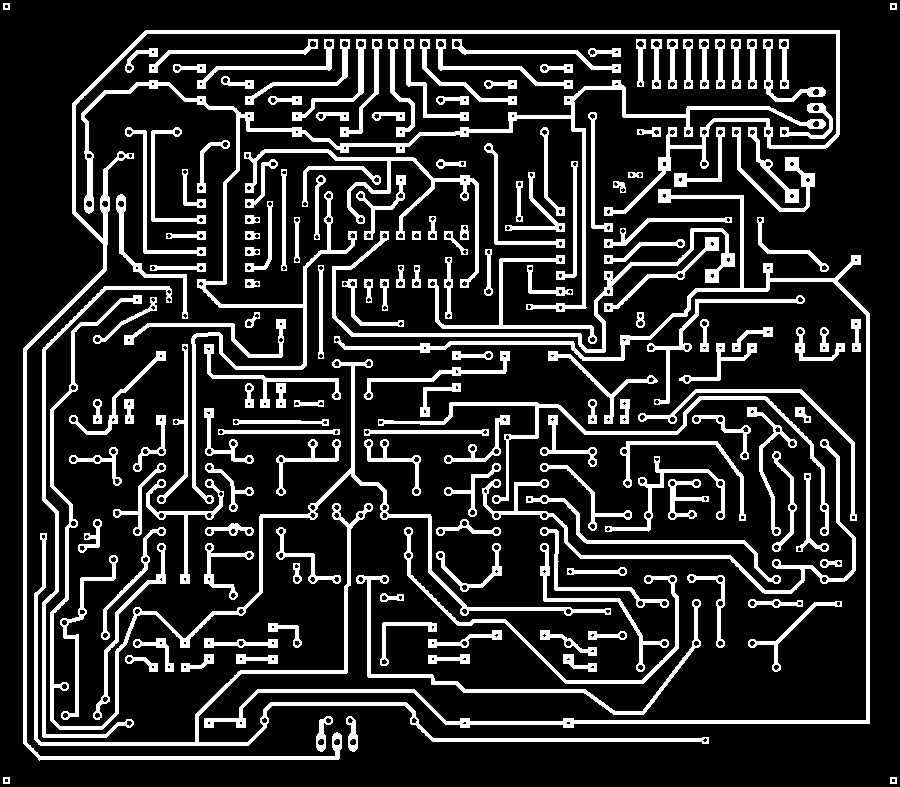
It took me several months to reduce the overall circuit size to incoporate all the components within a PCB of size 14.3cm x 12.5cm. More over I have routed all tracks on a single sided PCB board. So far I could not find any other compact circuit like this one in internet with similar 1/4W components in its place.
The circuit is redesigned with eagle software. The screenshot of the routed design is shown below.
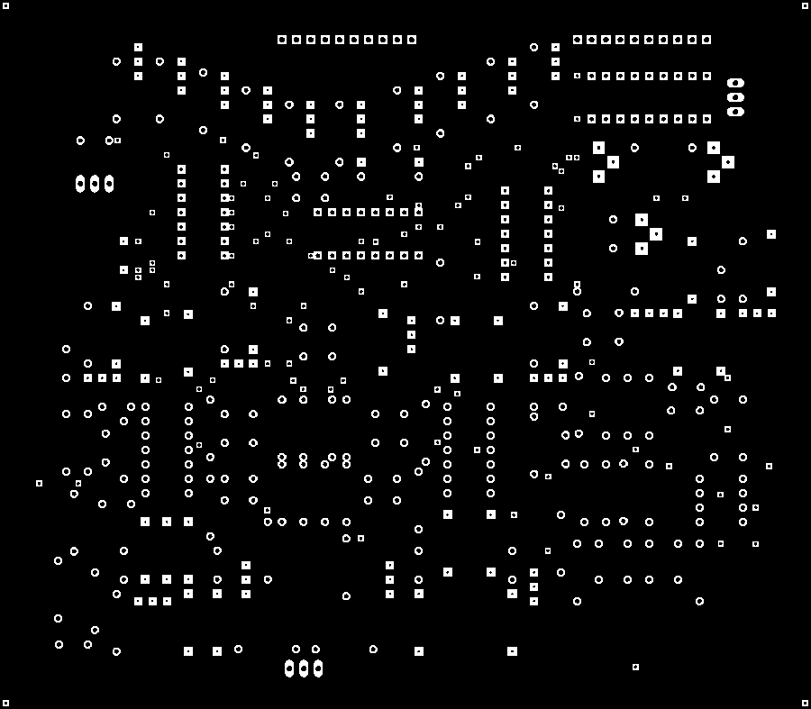
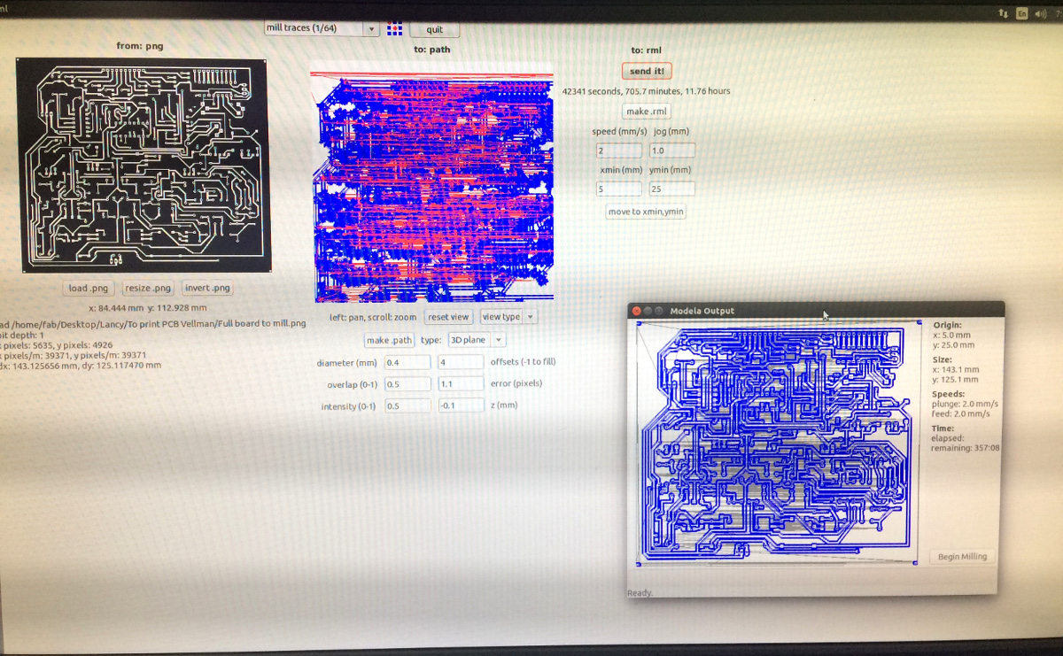
The circuit is exported for the milling operation in png format. The exported figures for milling the surface and drilling the holes are shown below.
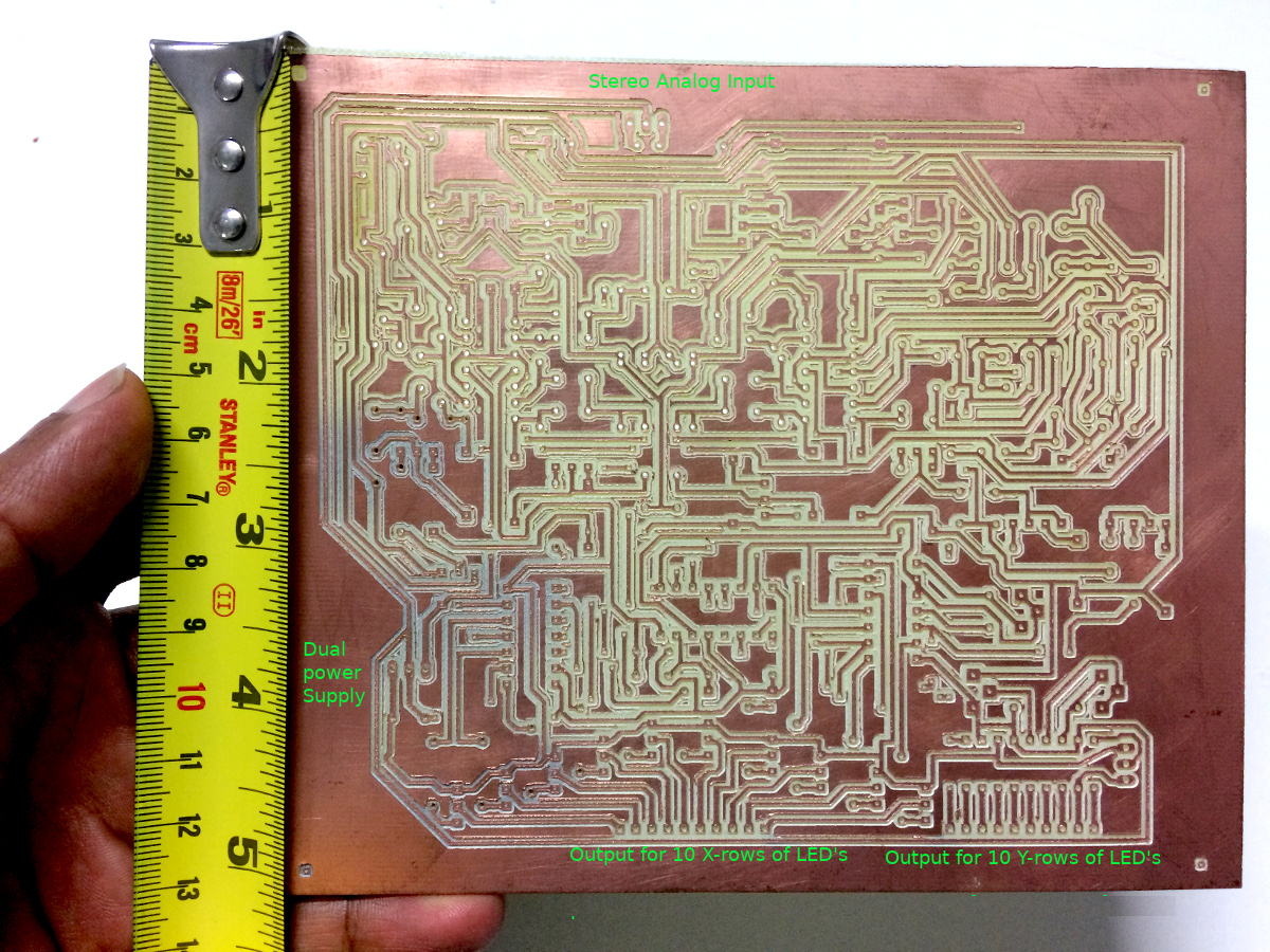
The final PCB board was realised from single sided FR4 Copper Clad Circuit Board. The milling operation for the same was done with a minimum tool speed of 1.5 to 2mm/s. The milling bit worn out at the end of operation. It is not recommended to use FR4 PCB with a tool bit with moderate hardness or else go for HRC level toolbits to sustain. The FR4 PCB after milling, the milled surface is semi-permeable to light. You can see the same in below pictures. There were holes with different sizes, hence smaller holes below 0.75mm standard sizes need to be manually drilled.
I believe, major portion of this project upgradation is completed here. The remaning task will be soldering followed by testing with the 10x10 Matrix display LED board. All these components are 1/4W and not available in fabinventory, obviously boughtout items. I hope this upgradation will be finishing soon fulfilling a 15 year dream.. ThankYou.