
- This week's lecture : Lecture
- Fab Tutorial Link : Tutorials
- Fab Tool's List : Tools List
Assignments:
- measure something: add a sensor to a microcontroller board that you have designed and read it
What I did this week?
- Designed and developed circuit board for reading input device.
- Programmed the board with the help of datasheet.
- Documented the processes and included all files for download.
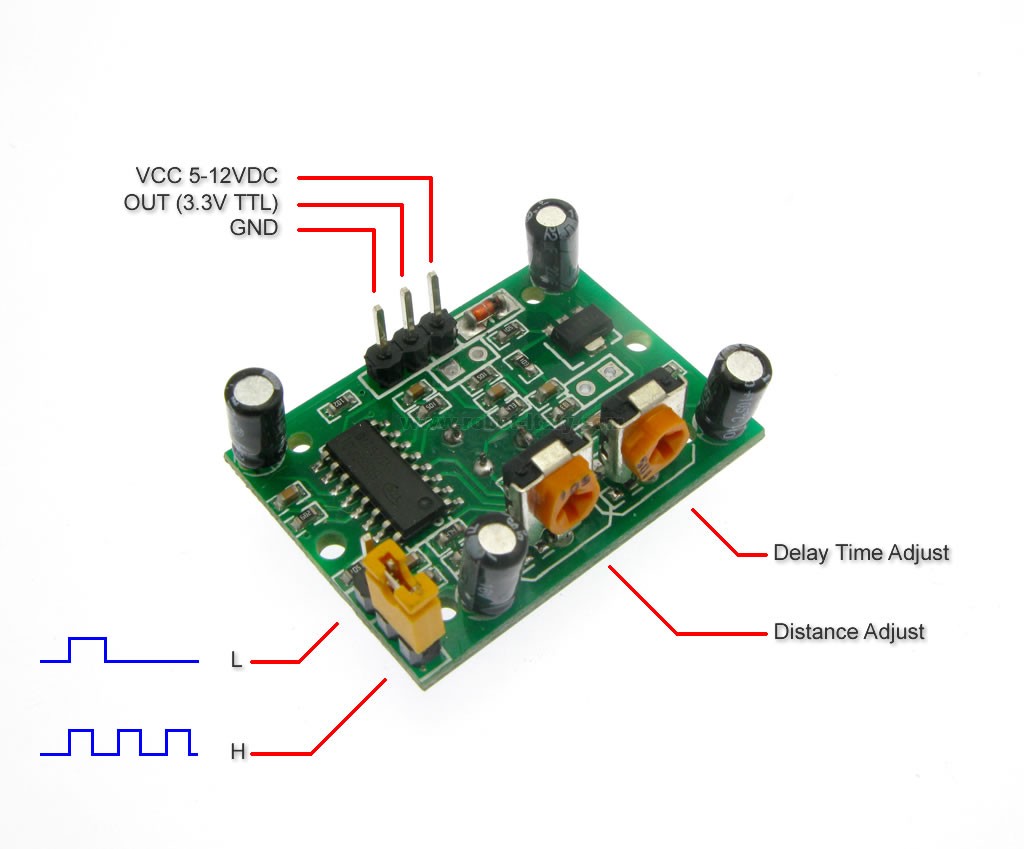
Input devices available in fablab are different switched, PIR, ultrasonic, hall effect sensor, temperature sensor, light sensor and accelerometer. I decided to try PIR sensor for this week's assignment.
PIR sensor
PIR, Passive Infrared, sensor senses Infrared light radiated from objects. So they are used for motion detection. PIR devices do not generate or radiate any energy for detection purposes, which is why the term 'passive'. PIRs are basically made of a pyroelectric sensor which can detect levels of infrared radiation.
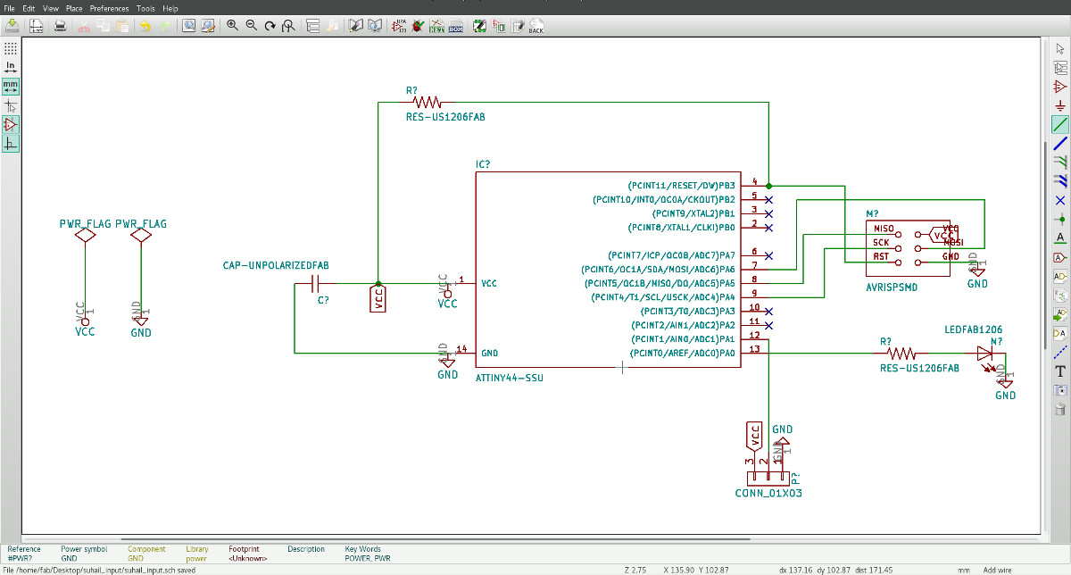
Electronic design
I started designing using Kicad. I decided to use attiny44 for this assignment. All I need is an LED and a 1x3 header pin for connecting PIR. According to datasheet, ATtiny44 chip has two ports - PORTA and PORTB. Port A is a 8-bit bi-directional I/O port and Port B is a 4-bit bi-directional I/O port. I just need two pins for this assignment. Led was connected to 13th pin which is PA0 and PIR was connected to 12th pin which is PA1. I used orange color LED (rating details : digikey.com - 160-1403-1-ND).
Calculating resistor value,
R = (V - VL)/IL
Where V = 5V,
VL (LED voltage rating) = 2V,
IL (LED current rating) = 20mA,
therefore R = 100 Ohm.
Here is my schematic diagram.
PCB looks like this.
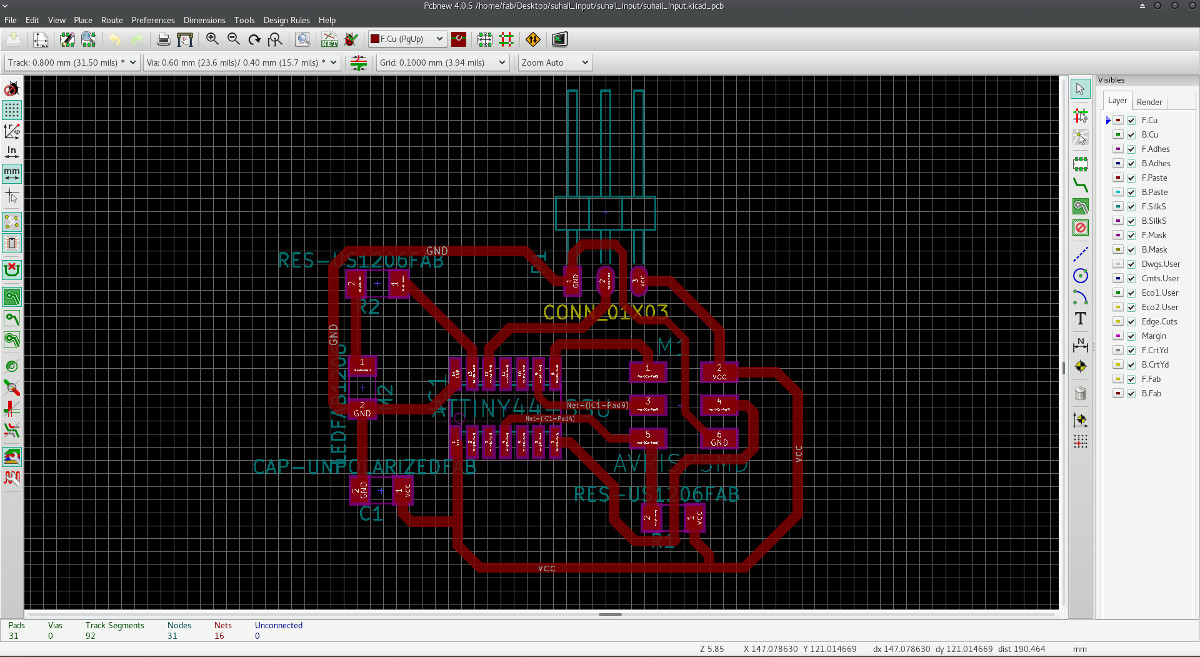
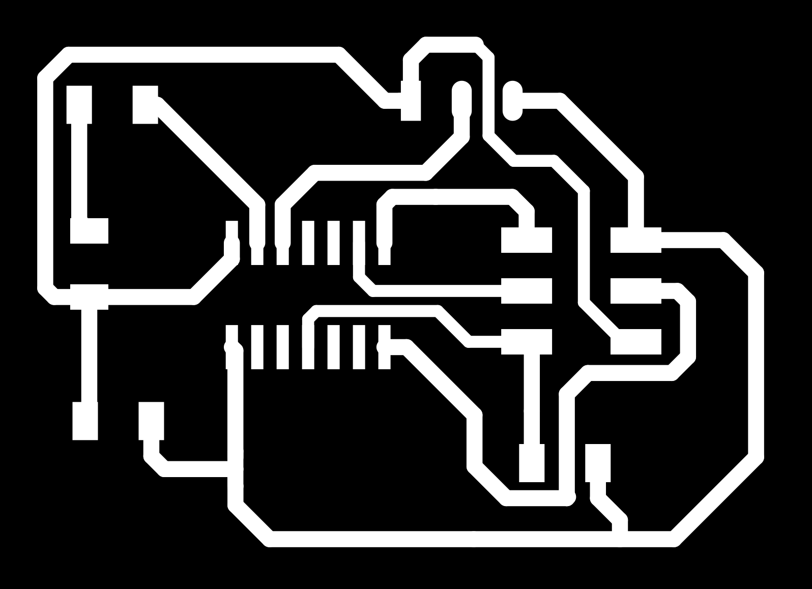
I exported the output into SVG format and trace & cutout files were generated.
Traces image
Cutout image

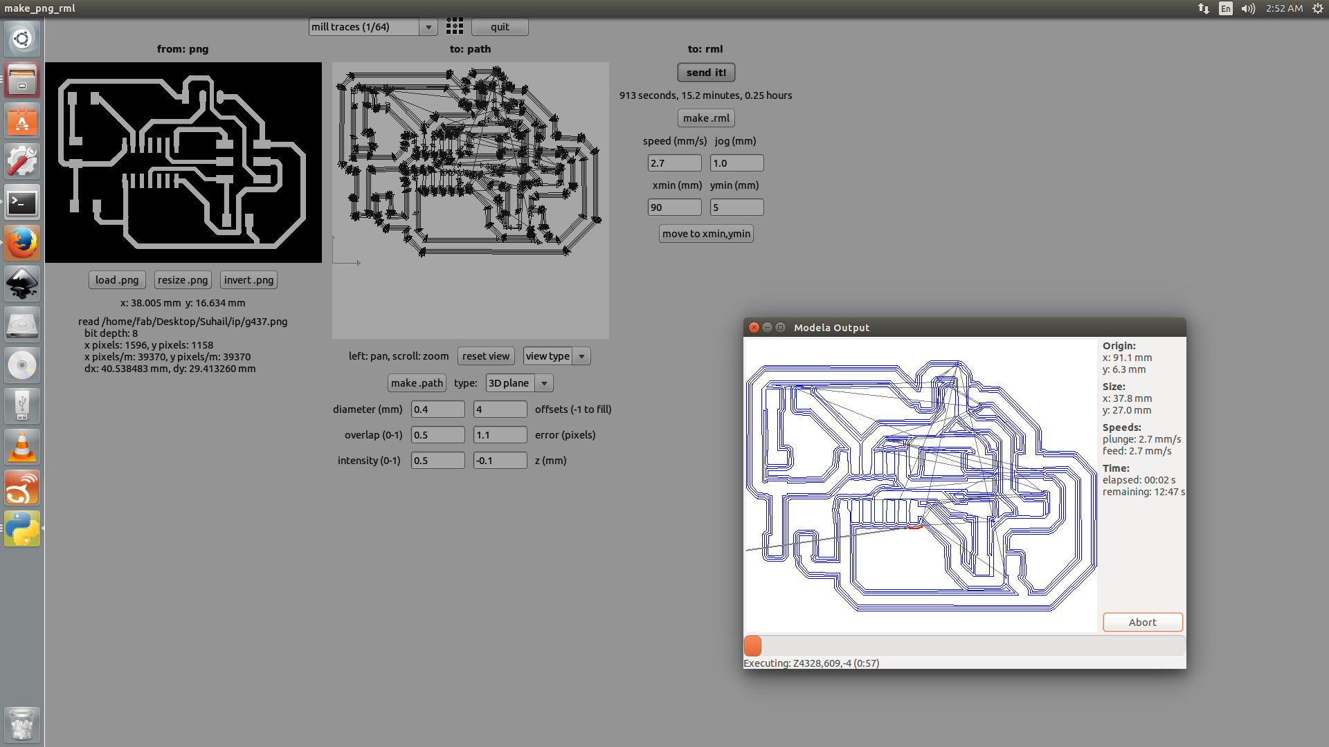
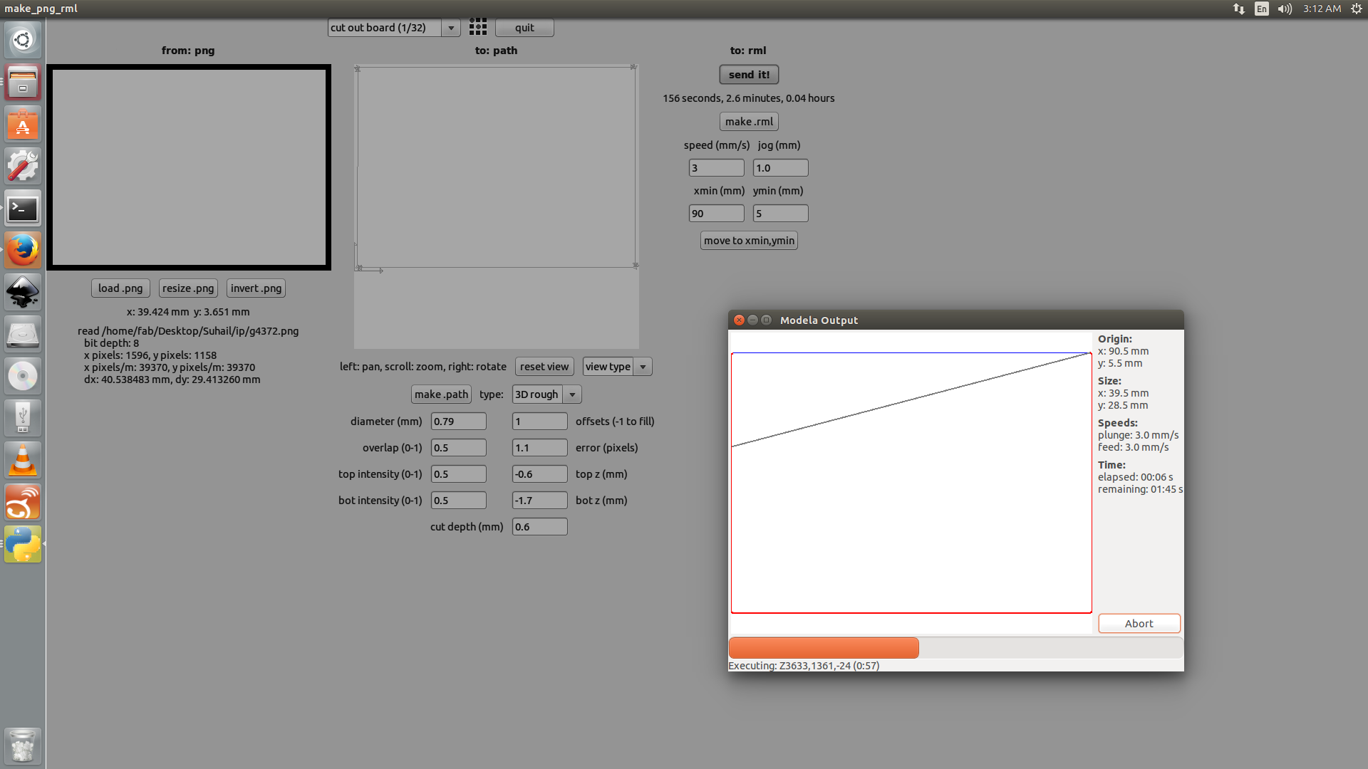
These file were fed to modella.
Milling PCB in Modella MDX
PCB cutout in modella
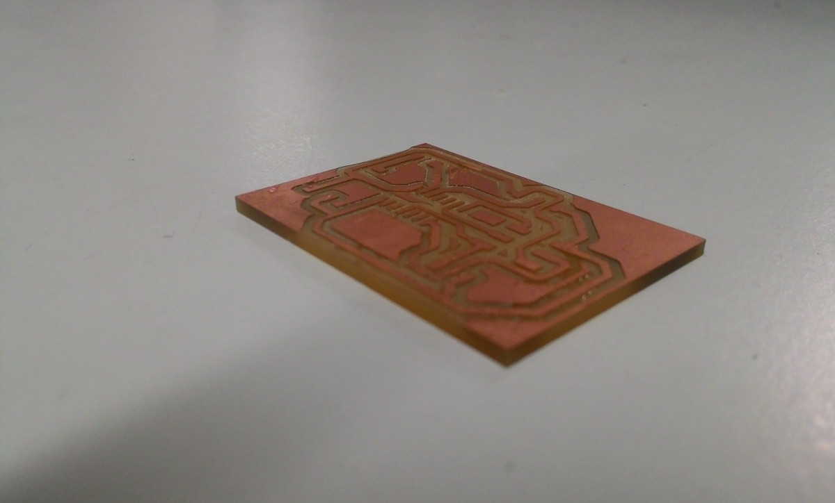
Here is the board before stuffing
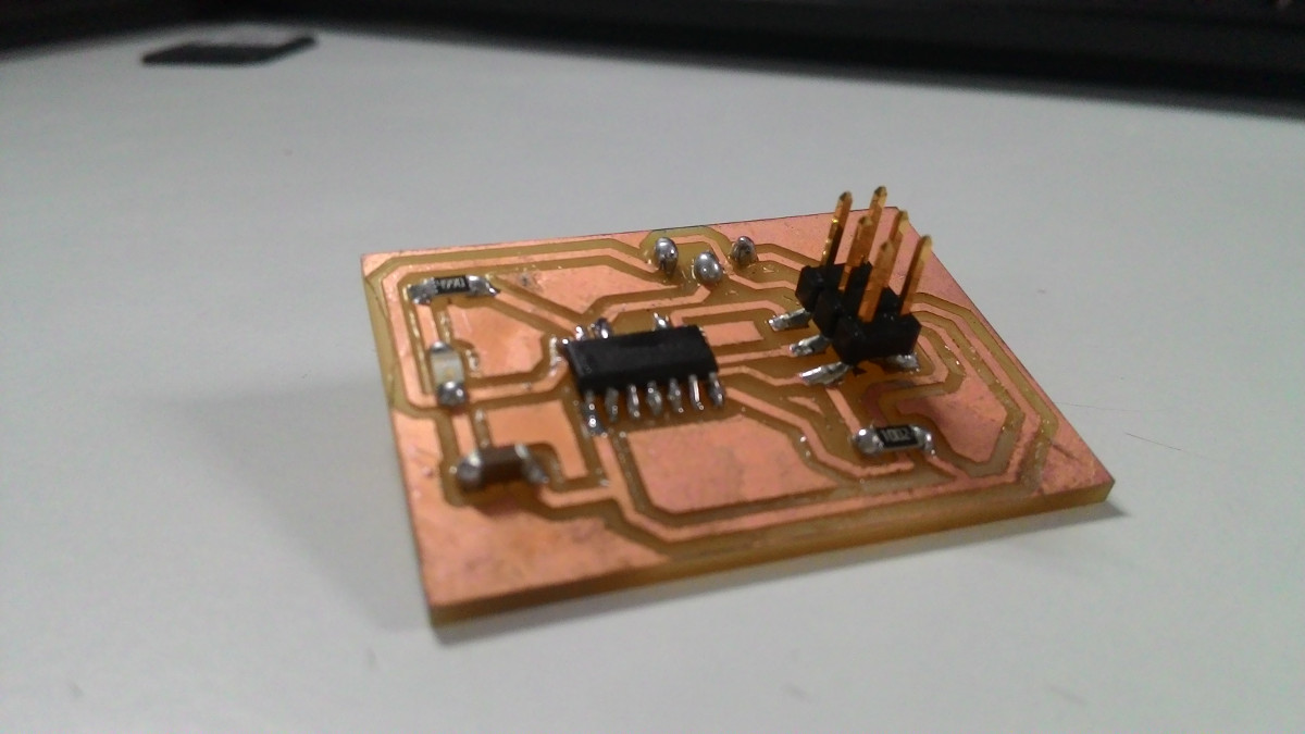
PCB after stuffing all components.
Programming
LED is connected to PA0. So data direction register should be 0b00000001. Similarly, input device PIR is connected to PA1. Final code is
#include <avr/io.h>
#define F_CPU 20000000         // External frequency of crystal oscillator.
#include <util/delay.h>
int main(void)
{
  DDRA=0b00000001;  //Output - LED at PA0
  PINA= 0b00000010; //Input  - PIR at PA1

while(1)
{
  if (PINA & (1<<PA1)) {
  PORTA=0b00000001;
}else {
  PORTA=0b00000000;
  }
}
}