
- This week's lecture : Lecture
- Fab Tutorial Link : Tutorials
- Fab Tool's List : Tools List
What I did this week?
- Tested 3D printer with various parameters.
- Designed and printed a model which can't be made subtractively.
- Scanned 3D image of an object
This week we were taught about 3D printing and scanning techniques. We were asked to complete the following assignments for this week.
Assignments:
- group project: test the design rules for your printer(s)
- design and 3D print an object (small, few cm) that could not be made subtractively
- 3D scan an object (and optionally print it) (extra credit: make your own scanner)
3D Printing
3D printing, also known as additive manufacturing (AM), refers to processes used to synthesize a three-dimensional object in which successive layers of material are formed under computer control to create an object. Objects can be of almost any shape or geometry and are produced using digital model data from a 3D model or another electronic data source such as an Additive Manufacturing File (AMF) file. --wikipedia--
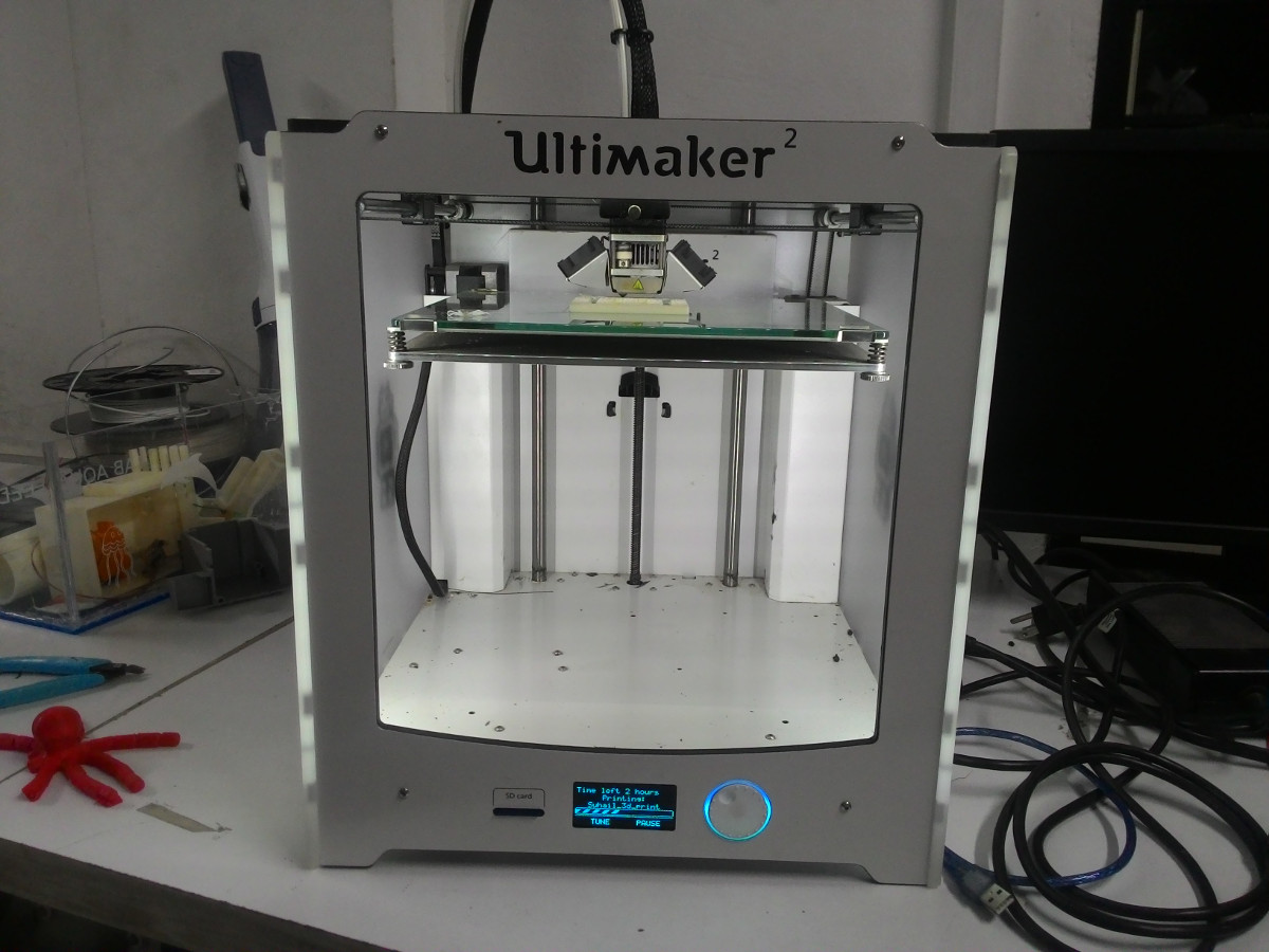
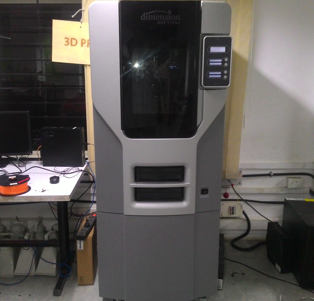
In our FabLab, we have two models of 3D printers. One is Ultimaker-2 and the other one is dimension SST 1200es.
Group Assignment: Testing 3D Printer
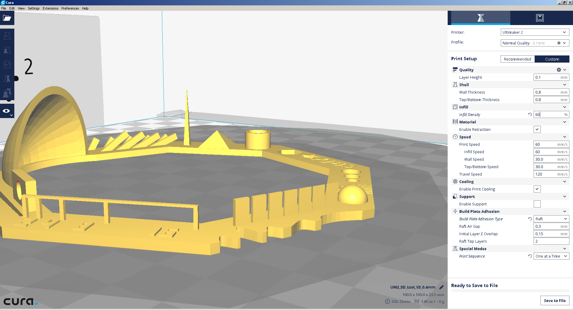
For 3D printer testing, we decided to try a design from thingiverse in ultimaker 2.
This include the following tests.
- Nut, Size M4 Nut should fit perfectly
- Wave, rounded print
- Star, Sharp Edges
- Name, Complex Shapes
- Holes, Size 3, 4, 5 mm
- minimal Distance: 0.1, 0.2, 0.3, 0.4, 0.5, 0.6, 0.7 mm
- Z height: 0.1, 0.2, 0.3, 0.4, 0.5, 0.6, 0.7, 0.8, 0.9, 1.0, 1.1 mm
- Wall Thickness: 0.1, 0.2, 0.3, 0.4, 0.5, 0.6, 0.7 mm
- Bridge Print: 2, 4, 8, 16 mm
- Sphere, Rounded Print 4.8mm height
- Sphere Mix, 7 mm height
- Pyramide, 7 mm height
- Pyramide, 7 mm height
- Warp, does it bend?
- 3D Print Font, optimized for 3D printing
- Surface, Flatness
- Size, 100 x 100mm x 23.83 (10mm width)
- Spike, minimum Layer Time, 21 mm height from Bottom (include Baseplate)
- Hole in Wall, 4 mm diameter, check for proper print
- Raft Test, raft should be just under the model
- Retract Travel, check retract settings for longer travel
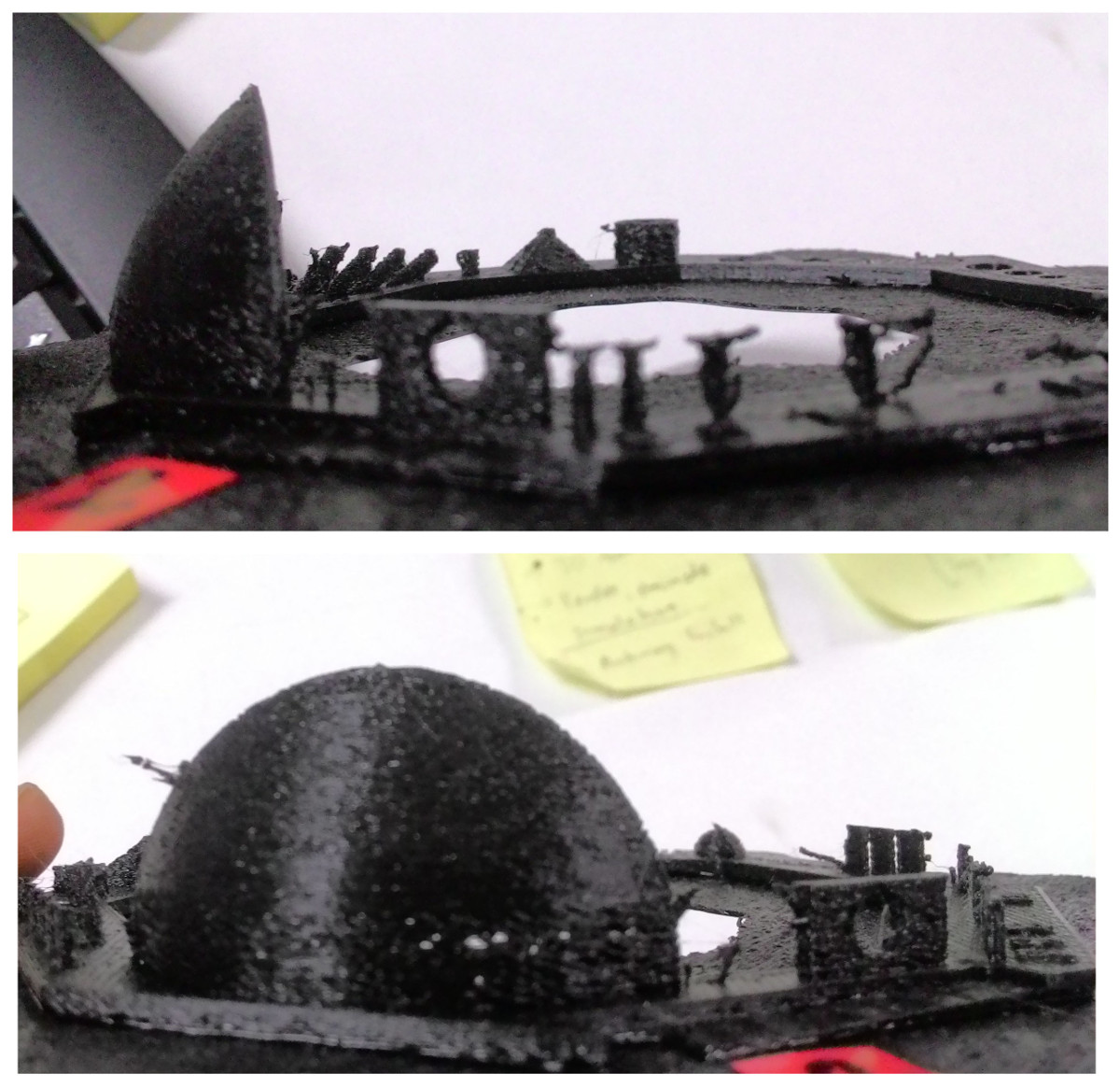
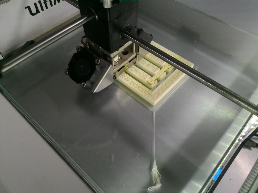
First we printed the design using values from the designer. Below is the image of our first print. Object was not printed well. There was no bridge, the dome shape's bottom section was imperfect, which is clearely visible from image below. Its caused because of large retraction value.
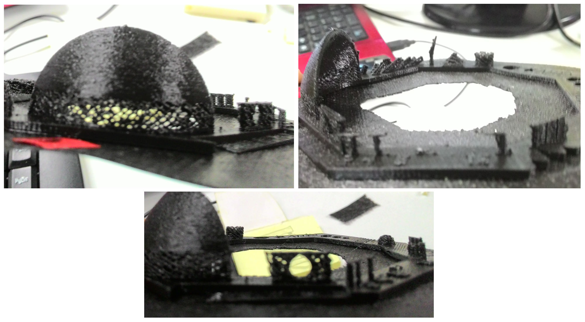
Second design was printed with lower retraction value, but almost same result was obtained at dome and bridge area. Other sections were almost okay. Modified retraction value is 2mm (initial value was 6.5mm)
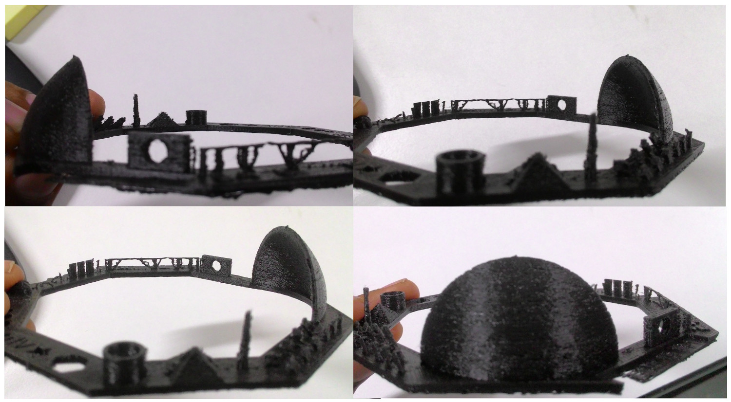
We printed another one with retraction = 1.5mm. Now the result was comparatively better but still bridge was not okay. Everything else is fine.
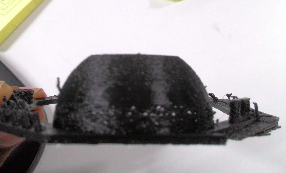
We decided to change fill rate too. Our new retraction and fill rate values are 0 and 60 respectively. Now everything is fine. Bridge is not perfect but still its better than previous designs.
Assignment: 3D Printing
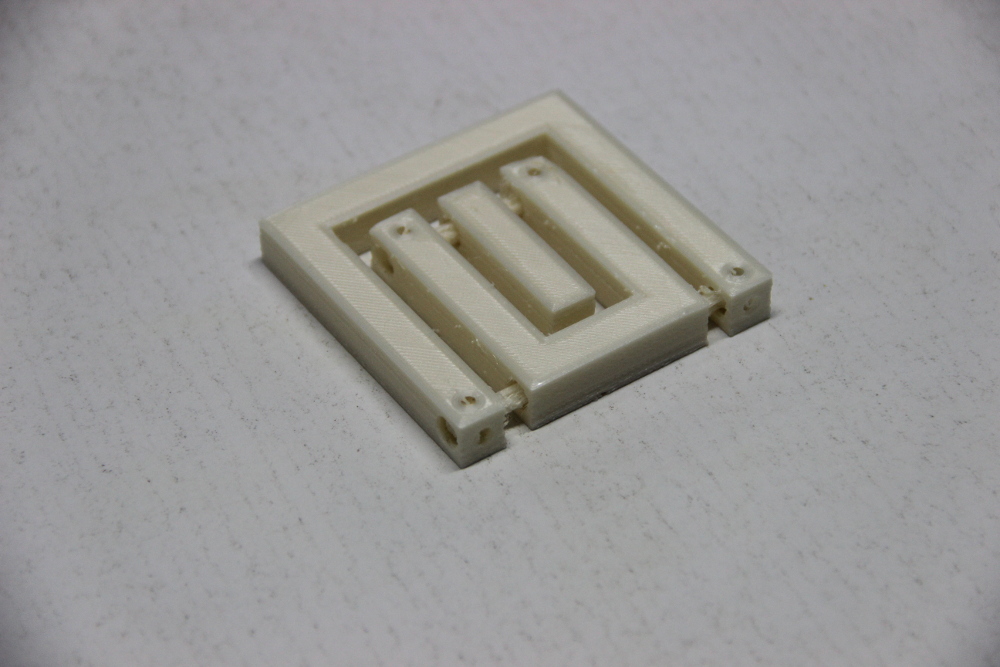
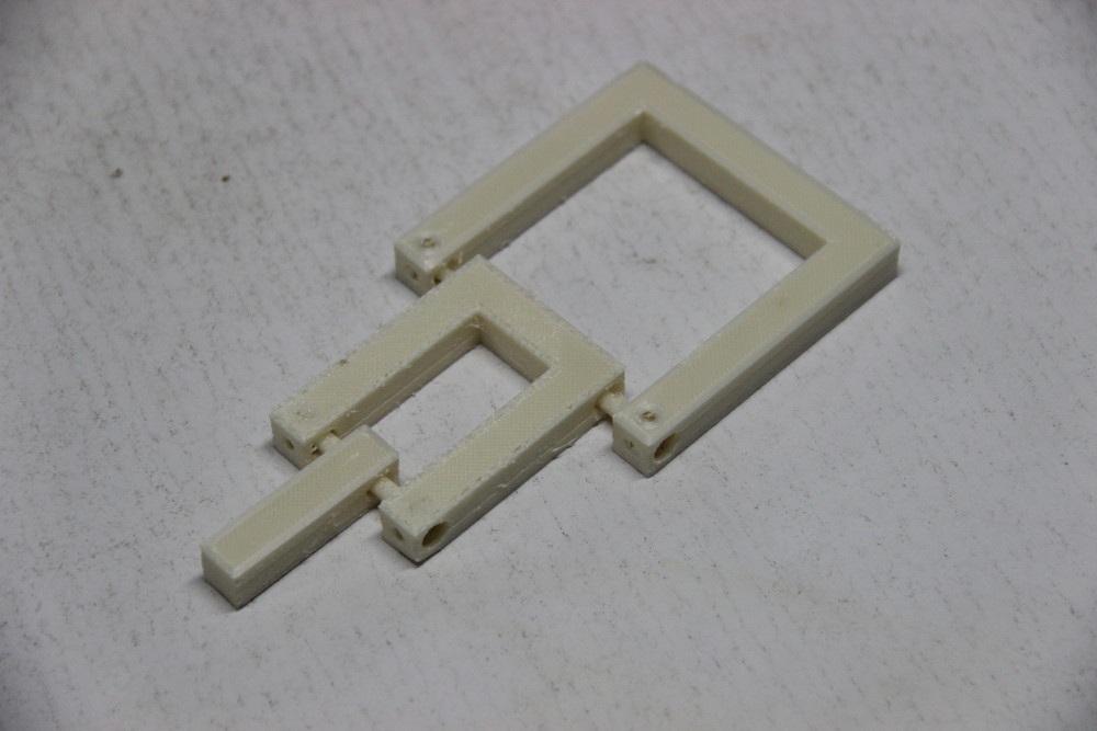
For 3D printing, I drew a simple design myself :).
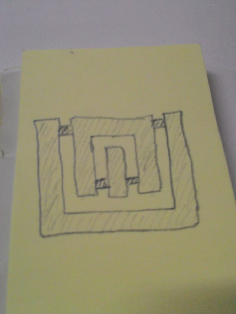
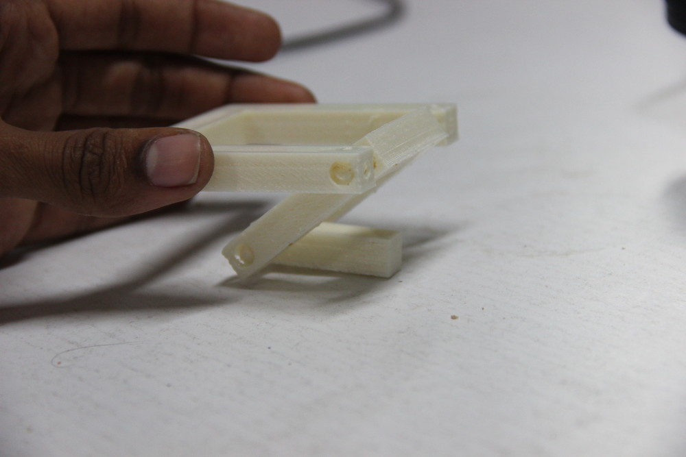
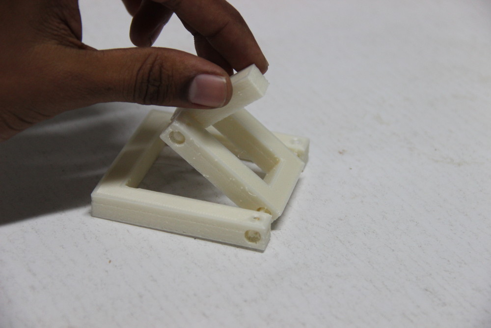
Here each item is locked with its child item. This item is difficult to build by subtractive method because of the ball and socket which locks each item together.
I started designing using OpenScad. I like its programatic approach for simple designs.
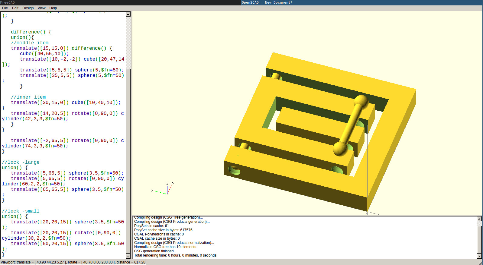
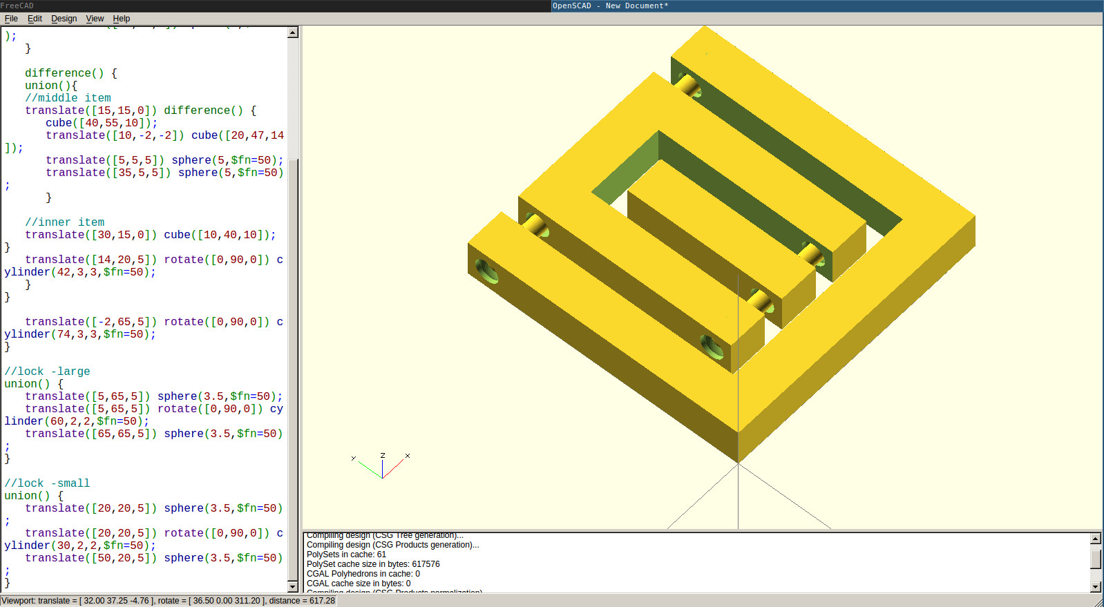
Here is my code for the above design.
difference() {
union() {
  //outer item
  difference() {
    cube([70,70,10]);
    translate([10,10,-2]) cube([50,62,14]);
        translate([5,65,5]) sphere(5,$fn=50);
        translate([65,65,5]) sphere(5,$fn=50);
  }

  difference() {
    union(){
      //middle item
      translate([15,15,0]) difference() {
      cube([40,55,10]);
      translate([10,-2,-2]) cube([20,47,14]);
      translate([5,5,5]) sphere(5,$fn=50);
      translate([35,5,5]) sphere(5,$fn=50);
      }

      //inner item
      translate([30,15,0]) cube([10,40,10]);
    }
  translate([14,20,5]) rotate([0,90,0]) cylinder(42,3,3,$fn=50);
  }
}

translate([-2,65,5]) rotate([0,90,0]) cylinder(74,3,3,$fn=50);
}

//lock -large
union() {
  translate([5,65,5]) sphere(3.5,$fn=50);
  translate([5,65,5]) rotate([0,90,0]) cylinder(60,2,2,$fn=50);
  translate([65,65,5]) sphere(3.5,$fn=50);
}

//lock -small
union() {
  translate([20,20,5]) sphere(3.5,$fn=50);
  translate([20,20,5]) rotate([0,90,0]) cylinder(30,2,2,$fn=50);
  translate([50,20,5]) sphere(3.5,$fn=50);
}
I exported the design in stl format and opened in Cura.
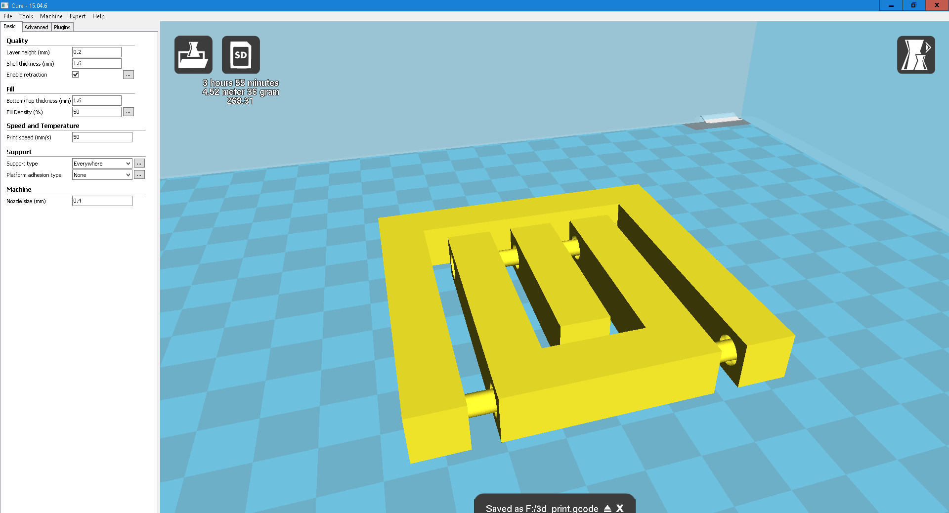
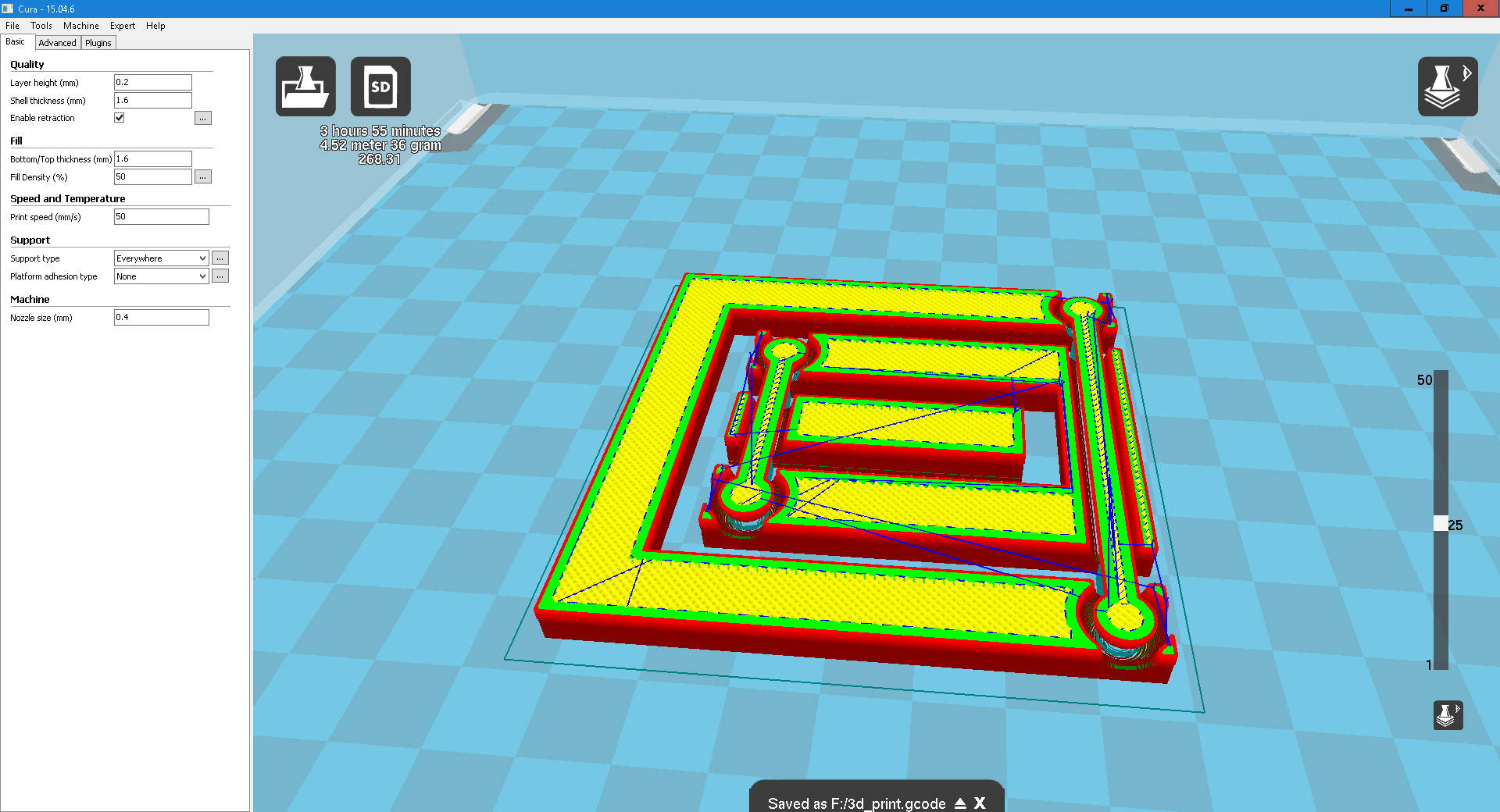
Finally gcode file was saved into memory card and fed into the Ultimaker 2. The gcode is used mainly in computer-aided manufacturing to control automated machine tools. It is defined by instructions on where to move, how fast to move, and what path to follow. The most common situation is that, within a machine tool, a cutting tool is moved according to these instructions through a toolpath and cuts away material to leave only the finished workpiece. The same concept also extends to noncutting tools such as forming or burnishing tools, photoplotting, additive methods such as 3D printing, and measuring instruments.
Here are some photos of the final output.
Downloadable links are available at the bottom of the page.
Assignment: 3D Scanning
A 3D scanner is a device that analyses a real-world object or environment to collect data on its shape and possibly its appearance (e.g. colour). The collected data can then be used to construct digital three-dimensional models. -Wikipedia-
Using Kinect XBOX 360
Kinect is a line of motion sensing input devices by Microsoft for Xbox 360 and Xbox One video game consoles and Windows PCs. Based around a webcam-style add-on peripheral, it enables users to control and interact with their console/computer without the need for a game controller, through a natural user interface using gestures and spoken commands. -Wikipedia-
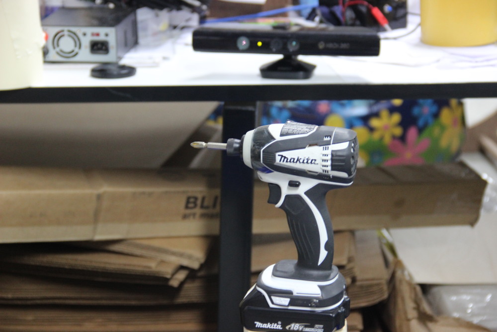
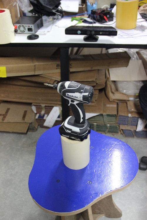
I used Kscan3D software for processing scanning. Here this application takes a series of photos while the object is being rotated. Software then combines all images to form the 3D shape. I selected no.of scans as 40 and delay between image capture as 4s. I took a driller to scan and placed it infront of Kinect, above a chair to adjust height.
40 image were taken with 4s gap in between each shot. I rotated the object at particular angles during this interval, so that the object was rotated 360 degree by the end of scanning. All images were taken well. Below is a screenshot taken after capturing all photos.
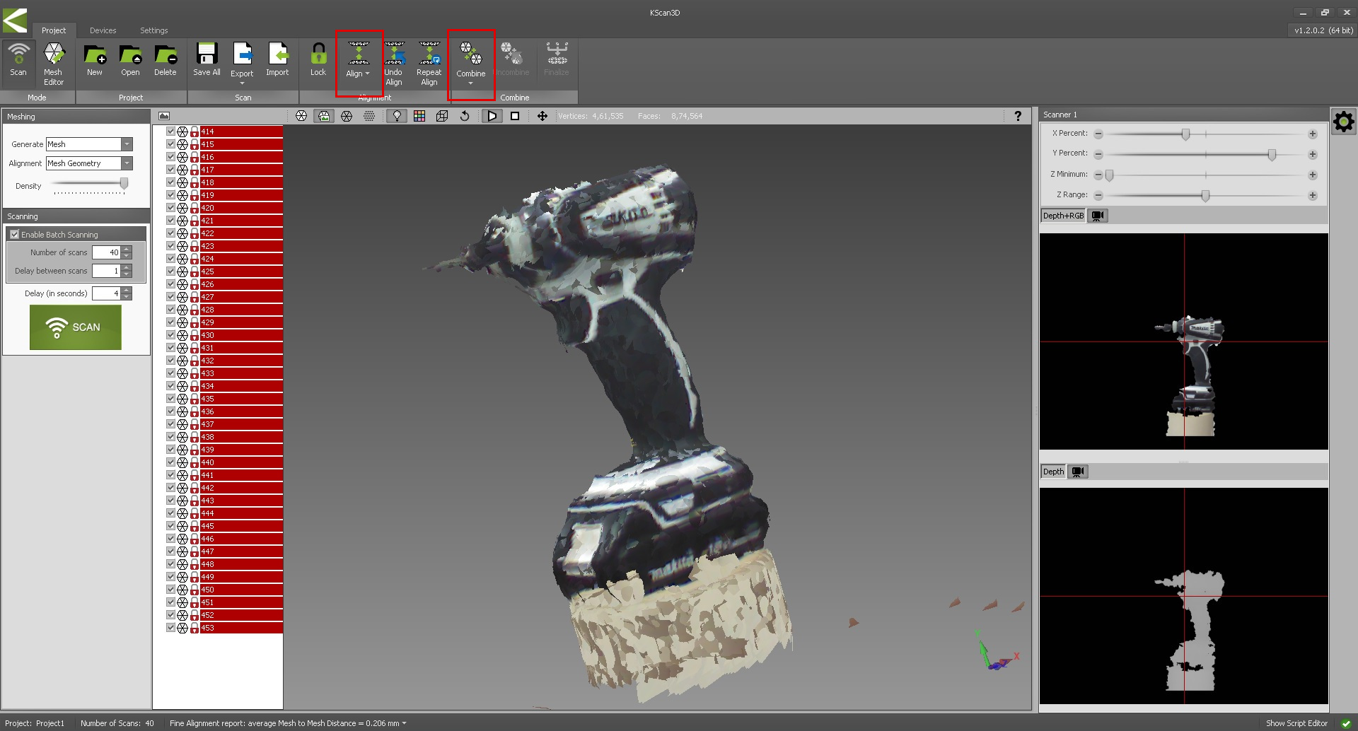
After that I selected Align option from menu. All images were grouped into a single one. Then I selected Combine option from menu, for fine tuning and generating final 3D image. Here is the screenshot.
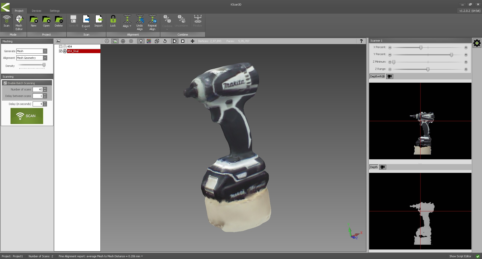
As you can see, the drill bit was lost in the final image. I exported the file in both STL and PLY formats. Sketchfab view is available below. Downloadable links are also available below.