
- This week's lecture : Lecture
- Fab Tutorial Link : Tutorials
- Fab Tool's List : Tools List
Assignments:
- automate your machine, document the group project and your individual contribution
What I did this week?
- Added electronic components to the machine
- Learned to use stepper motor
- Programmed the machine
This week we are doing the second part of our group project. In week 9 we had completed the mechanical parts. This week is about automating the movements. We have to add necessary electronic boards and program them. Our group page can accessed from here.
My duty this week was to program the board. Before jumping into the programming section, let me explain our electronic setup. As you can see, we have two stepper motors in our project, one for azimuth angle and other one for altitude. These stepper motors are connected to a RAMP1.4 board which can drive upto 5 stepper motors using Pololu stepper controller modules. This RAMPS1.4 board is connected on the top of an arduino mega development board.
RAMPS1.4
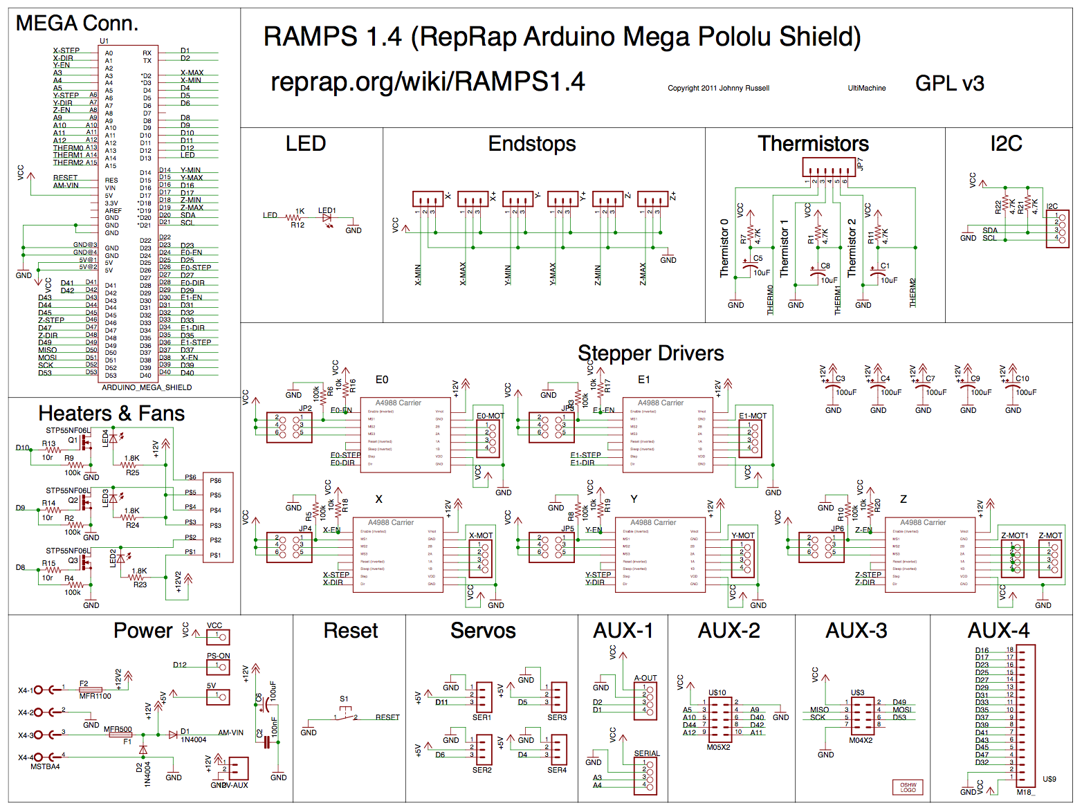
Ramps is short for reprap Arduino mega pololu shield, it is mainly designed for the purpose of using pololu stepper driven board (similar to 4988 driven board). Ramps can only work when connected to its mother board Mega 2560 and 4988/DRV8825.
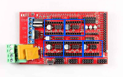
In image above, I have marked 4 squares, where we can add the Pololu stepper control modules. Top two are named as E0 and E1. Bottom 3 are named as X,Y and Z respectively. Z can control 2 stepper motors. Note that we have connected our Pololu modules in E0 and E1. An annotation diagram is given below.
The shield has following features:
- Standard interfaces (as that of extruder)
- Reserved GCI like I2C and RS232Reserved GCI like I2C and RS232
- MOSFET are applied to the heater/ fan and thermistor circuit.
- Adding another 5A to protect the component parts.
- An 11A fuse is added to the hotbed
- Support 5 stepper drive board
- The adoption of Pin Header as pololu makes it more convenient to repair or change.
- I2C and SPI are reserved for expanding
- All the MOSFET can be controlled by PWM
- Use the interface of servo motor to adjust the level of printing platform automatically.
- Adding a SD module for SD ramps module.
- LED can indicate the status of the heater (the open and close of MOS).
- 2 stepper motor for Z axis in parallel.
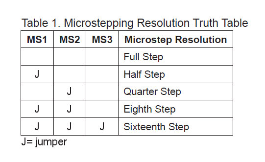
In above two images there are 3 jumper pins for each pololu shield holders. They are used for microstepping the stepper motor. Microstepping jumper settings are shown below.
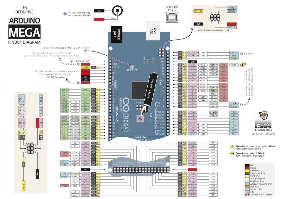
Arduino Mega
The Mega 2560 is a microcontroller board based on the ATmega2560. It has 54 digital input/output pins (of which 15 can be used as PWM outputs), 16 analog inputs, 4 UARTs (hardware serial ports), a 16 MHz crystal oscillator, a USB connection, a power jack, an ICSP header, and a reset button. It contains everything needed to support the microcontroller; simply connect it to a computer with a USB cable or power it with a AC-to-DC adapter or battery to get started.
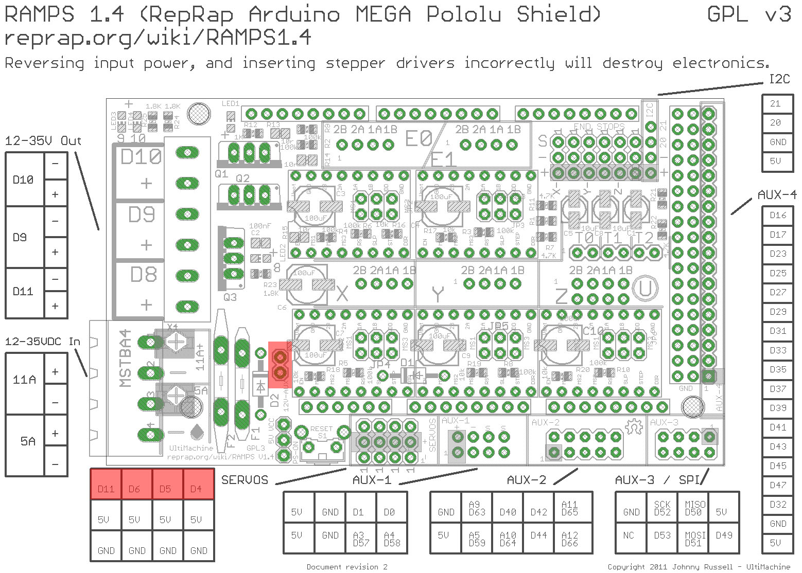
We had mounted the RAMPS board over Arduino Mega. Schematic diagram showing connection between RAMPS and arduino mega is given below.
Here is the pinout diagram for arduino mega.
Pololu
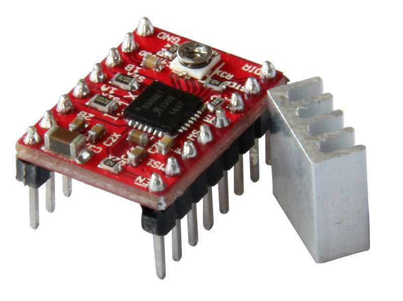
The A4988 is a microstepping driver for controlling bipolar stepper motors which has built-in translator for easy operation. This means that we can control the stepper motor with just 2 pins from our controller, or one for controlling the rotation direction and the other for controlling the steps.
The Driver provides five different step resolutions: full-step, haft-step, quarter-step, eight-step and sixteenth-step. Also, it has a potentiometer for adjusting the current output, over-temperature thermal shutdown and crossover-current protection. Its logic voltage is from 3 to 5.5 V and the maximum current per phase is 2A if good addition cooling is provided or 1A continuous current per phase without heat sink or cooling.
Programming
I decided to test stepper motor control first. I connected the RAMPS board into arduino and connected a Pololu sheld at E0 position of the RAMPS. Also all 4 pins were connected to pins named 2A, 2B, 1A & 1B. Now, according to the schematic diagram shown above, step pin and direction pin of E0 are connected to D26 & D28 of arduino. By default stepper control is in 1/16 microstepping.
Therefore total no.of steps required for 360 deg rotation = 200*16 = 3200
I wrote a program to rotate stepper by 360 deg. High and low pulses were generated inside a for loop 3200 times. Below is the sample code.
const int stepPin = 26;
const int dirPin = 28;

void setup() {
// Sets the two pins as Outputs
pinMode(stepPin,OUTPUT);
pinMode(dirPin,OUTPUT);

for (int i=0;i<3200;i++) {
  digitalWrite(dirPin,HIGH);
  digitalWrite(stepPin,HIGH);
  delayMicroseconds(1000);
  digitalWrite(stepPin,LOW);
  delayMicroseconds(1000);
}

}
void loop() {
}
While running this code, unfortunately nothing was happening. Our instructor asked to check the enable pin. Enable pin corresponding to E0 is D24. Inorder to enable this pin Low signal should be given. I edited the code as below.
const int enablePin = 24;
const int stepPin = 26;
const int dirPin = 28;

void setup() {
// Sets the two pins as Outputs
pinMode(enablePin,OUTPUT);
pinMode(stepPin,OUTPUT);
pinMode(dirPin,OUTPUT);

//enable E0
digitalWrite(enablePin,LOW);

for (int i=0;i<3200;i++) {
  digitalWrite(dirPin,HIGH);
  digitalWrite(stepPin,HIGH);
  delayMicroseconds(1000);
  digitalWrite(stepPin,LOW);
  delayMicroseconds(1000);
}

}
void loop() {
}
And, now it works!!!
Now comes the calculation part. Theoretical informations for this are explained in machine week page. For the calculations we need below inputs.
- RA and declination if celestial body
- Current date and time
- my latitude and longitude
Also I declared an array which stores no.of days passed until each month. It varies in leap year. This is required for calculation.
//no.of days from beginning of year(normal)
//jan-0, feb-31 etc
int days[] = {0,31,59,90,120,151,181,212,243,273,304,334};
//no.of days from beginning of year(leapyear)
int days_leap[] = {0,31,60,91,121,152,182,213,244,274,305,335};
//declination - {degree,minute}
int ip_dec[] = {-19,52.74};
//right ascension - {hour,minute}
int ip_ra[] = {19,53};
//time - {hour,minute} in 24HRS format
int ip_t[] = {16,10};
//latitude - {value in decimal}
float ip_lat = 10.05542;
//logitude - {value in decimal}
float ip_long = 76.35792879999997;
//date - date,month,year
int ip_date[] = {19,4,2017};
Note: Hardcoded DEC and RA values seen above are that of Moon.
Each calculations were defined as different functions.
To convert DEC in (degree,minute) to degree
// to convert value in (degree,min) to degree
float dec_to_degree(int val[]) {
float result;
result = val[0] + (val[1]/60.0);
return result;
}
To convert RA in (hour,nimute) to degree
// to convert value in (hour,min) to degree
float ra_to_degree(int val[]){
float result;
result = (val[0] + (val[1]/60.0))*15;
return result;
}
To convert time in (hour, minute) to hour
// to convert value in (hour,min) to hour
float time_to_hour(int val[]){
float result;
result = val[0] + (val[1]/60.0);
return result;
}
To find LST (Local Sidereal Time)
    //Local Sidereal Time
    //longitude,time,date as inputs
    float get_lst_value(float lngt, int t[], int dt[]) {
    float lst;
    //for calculate from epoch (reference date is J2000)
    //days from J2000 upto 2017 is 6208.5
    float total_days = 6208.5+(dt[2]-2017)*365 + time_to_hour(t)/24;
    //if leap year, add one more day
    if ((dt[2] % 4) == 0) {
      total_days += 1;
      leap_year = 1;
}
    //add total days of current month and date
    //currently we processed only days in year
    if (leap_year == 1) {
  total_days = total_days + days_leap[dt[1]-1] + dt[0];
    }
    else {
  total_days = total_days + days[dt[1]-1] + dt[0];
    }
    //last element is time converted to GMT
    lst = float(100.46) + float((0.985647*total_days)) + float(lngt) + float(15*(time_to_hour(t)-5.5));
    return lst;
    }
To find HA
//HA = LST - RA
float get_ha() {
float lst_ = get_lst_value(ip_long, ip_t, ip_date);
float ra_ = ra_to_degree(ip_ra);
float ha = lst_ - ra_;
//float ha = (lst_ - ra_ + 360)- ((int)((lst_ - ra_ + 360)/360))*360;
return ha;
}
To find altitude
float get_altitude() {
float alt = asin(sin(dec_to_degree(ip_dec)*pi/180)*sin(ip_lat*pi/180)+cos(dec_to_degree(ip_dec)*pi/180)*cos(ip_lat*pi/180)*cos(get_ha()*pi/180));
return alt*180/pi;
}
To find azimuth
float get_azimuth() {
float a,az,ha;
a = acos((sin(dec_to_degree(ip_dec)*pi/180)-sin(get_altitude()*pi/180)*sin(ip_lat*pi/180))/(cos(get_altitude()*pi/180)*cos(ip_lat*pi/180)));
a = a*180/pi;
ha = get_ha();
if (sin(ha*pi/180) > 0) {
  az = 360-a;
}
else {
  az = a;
}
return az;
}
Initially the telescope should move to its home position, facing the North. After this, it should move according to the calculated azimuth and altitude angles from home position. The whole code should look like this.
int leap_year = 0;
//no.of days from beginning of year(normal)
//jan-0, feb-31 etc
int days[] = {0,31,59,90,120,151,181,212,243,273,304,334};
//no.of days from beginning of year(leapyear)
int days_leap[] = {0,31,60,91,121,152,182,213,244,274,305,335};

//{degree,minute}
int ip_dec[] = {-19,52.74};
//{hour,minute}
int ip_ra[] = {19,53};
//{hour,minute} in 24HRS format
int ip_t[] = {16,10};
//{value in decimal}
float ip_lat = 10.05542;
//{value in decimal}
float ip_long = 76.35792879999997;
//date,month,year
int ip_date[] = {19,4,2017};

float pi = 3.1415;

void setup() {
int i,j;
int base_correction = 0;

//Initiate Serial communication.
Serial.begin(9600);

Serial.print("Time: ");
Serial.print(ip_t[0]);
Serial.print(':');
Serial.print(ip_t[1]);
Serial.print("\nDate: ");
Serial.print(ip_date[0]);
Serial.print('/');
Serial.print(ip_date[1]);
Serial.print('/');
Serial.print(ip_date[2]);
Serial.print('\n');

//pins for setting home position
const int button_side = 32;
const int button_base = 16;
pinMode(button_side, INPUT);
pinMode(button_base, INPUT);
digitalWrite(button_side,HIGH);
digitalWrite(button_base,HIGH);

//STEPPER DATA
// defines pins numbers
const int enablePin_base = 24;
const int stepPin_base = 26;
const int dirPin_base = 28;
const int enablePin_side = 30;
const int stepPin_side = 36;
const int dirPin_side = 34;

pinMode(enablePin_base,OUTPUT);
pinMode(stepPin_base,OUTPUT);
pinMode(dirPin_base,OUTPUT);

pinMode(enablePin_side,OUTPUT);
pinMode(stepPin_side,OUTPUT);
pinMode(dirPin_side,OUTPUT);

//set enable pin
digitalWrite(enablePin_base,LOW);
digitalWrite(enablePin_side,LOW);

//finding home position for base(azimuth)
int button_base_val = digitalRead(button_base);
while (button_base_val == HIGH) {
digitalWrite(dirPin_base,HIGH);
digitalWrite(stepPin_base,HIGH);
delayMicroseconds(400);
digitalWrite(dirPin_base,HIGH);
digitalWrite(stepPin_base,LOW);
delayMicroseconds(400);
button_base_val = digitalRead(button_base);
}

//finding home position for side arm(altitude)
int button_side_val = digitalRead(button_side);
while (button_side_val == HIGH) {
digitalWrite(dirPin_side,LOW);
digitalWrite(stepPin_side,HIGH);
delayMicroseconds(700);
digitalWrite(dirPin_side,LOW);
digitalWrite(stepPin_side,LOW);
delayMicroseconds(700);
button_side_val = digitalRead(button_side);
}

//After reaching home position
float alt_val = get_altitude();
float azimuth_val = get_azimuth();

Serial.print("\nAltitude: ");
Serial.print(alt_val);
Serial.print('\n');
Serial.print("Azimuth: ");
Serial.print(azimuth_val);
Serial.print('\n');

//Home position for our telescope is 90 deg to earth surface
//But, 0 deg altitude means telescope should be parallel to earth surface
//So, altitude = 90-calculated_altitude

alt_val = 90-alt_val;

//Telescope is not allowed to move backward. We have set it move only anticlockwise(-ve direction)
//So if there is -ve value azimuth, its taken as +ve and move anticlockwise
//else azimuth = 360 - az, and moved anticlockwise
if (azimuth_val < 0) {
azimuth_val = abs(azimuth_val);
}
else {
azimuth_val = 360-azimuth_val;
}
/*
Serial.print('\n');
Serial.print(alt_val);
Serial.print(';');
Serial.print(azimuth_val);
*/
/*
if (alt_val < 0) {
base_correction = 180;
alt_val = abs(alt_val);
}
if (azimuth_val < 0) {
azimuth_val = 360 + azimuth_val - base_correction;
}
else{
azimuth_val = azimuth_val + base_correction;
}

//azimuth should not be > 360 according to our mechanical setup
if (azimuth_val > 360) {
azimuth_val = azimuth_val -360;
}
*/
//converting above values to steps
//microstepping-1/16; 0.1125 deg = 1 step
alt_val = alt_val/0.1125;
azimuth_val = azimuth_val/0.1125;

/*
Serial.print(round(alt_val));
Serial.print(';');
Serial.print(round(azimuth_val));
Serial.print(';');
*/

//correction - gear ratio is 1:10
//alt_val = alt_val*10;
//azimuth_val = azimuth_val*10;
alt_val = alt_val*10;
azimuth_val = azimuth_val*10;

/*
Serial.print('\n');
Serial.print(alt_val);
Serial.print(';');
Serial.print(azimuth_val);
Serial.print(';');

*/
//feeding steps to motor
//base stepper
for (i=0; i<=azimuth_val; i++) {
//generate pulse for base motor
digitalWrite(dirPin_base,LOW);
digitalWrite(stepPin_base,HIGH);
delayMicroseconds(400);
//digitalWrite(dirPin_base,HIGH);
digitalWrite(stepPin_base,LOW);
delayMicroseconds(400);
}
for (j=0; j<=alt_val; j++) {
//generate pulse for side motor
digitalWrite(dirPin_side,HIGH);
digitalWrite(stepPin_side,HIGH);
delayMicroseconds(700);
//digitalWrite(dirPin_side,HIGH);
digitalWrite(stepPin_side,LOW);
delayMicroseconds(700);
}
}

void loop() {
// put your main code here, to run repeatedly:
}

// to convert value in (degree,min) to degree
float dec_to_degree(int val[]) {
float result;
result = val[0] + (val[1]/60.0);
return result;
}

// to convert value in (hour,min) to degree
float ra_to_degree(int val[]){
float result;
result = (val[0] + (val[1]/60.0))*15;
return result;
}

// to convert value in (hour,min) to hour
float time_to_hour(int val[]){
float result;
result = val[0] + (val[1]/60.0);
return result;
}

//Local Sidereal Time
//longitude,time,date as inputs
float get_lst_value(float lngt, int t[], int dt[]) {
float lst;
//for calculate from epoch (reference date is J2000)
//days from J2000 upto 2017 is 6208.5
float total_days = 6208.5+(dt[2]-2017)*365 + time_to_hour(t)/24;
//if leap year, add one more day
if ((dt[2] % 4) == 0) {
total_days += 1;
leap_year = 1;
}
//add total days of current month and date
//currently we processed only days in year
if (leap_year == 1) {
total_days = total_days + days_leap[dt[1]-1] + dt[0];
}
else {
total_days = total_days + days[dt[1]-1] + dt[0];
}
//last element is time converted to GMT
//lst = float(100.46) + float(((time_to_hour(t)-5.5)/24)*total_days) + float(lngt) + float(15*(time_to_hour(t)-5.5));
lst = float(100.46) + float((0.985647*total_days)) + float(lngt) + float(15*(time_to_hour(t)-5.5));
//lst = (100.46 + 0.985647 * total_days + float(lngt) + 15 * (time_to_hour(t)) + 360) - (((int)((100.46 + 0.985647 * total_days + float(lngt) + 15*(time_to_hour(t)) + 360)/360))*360);
//BRINGING VALUE B/W 0 & 360
//int temp = (lst/360)+1;
//lst = 360*temp - lst;
return lst;
}

//to find Hour Angle (HA)
//HA = LST - RA
float get_ha() {
float lst_ = get_lst_value(ip_long, ip_t, ip_date);
float ra_ = ra_to_degree(ip_ra);
float ha = lst_ - ra_;
//float ha = (lst_ - ra_ + 360)- ((int)((lst_ - ra_ + 360)/360))*360;
return ha;
}

//to calculate Altitude(ALT)
float get_altitude() {
float alt = asin(sin(dec_to_degree(ip_dec)*pi/180)*sin(ip_lat*pi/180)+cos(dec_to_degree(ip_dec)*pi/180)*cos(ip_lat*pi/180)*cos(get_ha()*pi/180));
return alt*180/pi;
}

//to calculate Azimuth(AZ)
float get_azimuth() {
float a,az,ha;
a = acos((sin(dec_to_degree(ip_dec)*pi/180)-sin(get_altitude()*pi/180)*sin(ip_lat*pi/180))/(cos(get_altitude()*pi/180)*cos(ip_lat*pi/180)));
a = a*180/pi;
ha = get_ha();
if (sin(ha*pi/180) > 0) {
az = 360-a;
}
else {
az = a;
}
return az;
}