Week 9 - Mechanical Design
Assignment
1. Create a machine.
Project Criteria
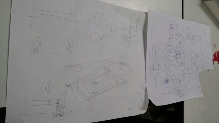
This week we have design and make a machine and this will be a group project. We had so many ideas in the begining. We discussed a lot for the first 3 days.
Major Criteria :
1. Design a machine (mechanism+automation), including the end effector
2. Build the passive parts and operate it manually
3. Document the group project and your individual contribution
We wanted to include both electronics and mechanical elements.
The machines should have atleast 2 axis of motion.
Briefing some of the initial ideas.
1. PLAbot : This is the first idea we had.
We are using PLA material for 3-D printing and the wastage of the material is very high.
We wanted to do recyle the wasted materials
and Recycler for used and waste PLA prints.
The wasted materials can be collected together and then processed to build the filament for further printing.
Challenges :
When we looked into the feasibility we found that the high temperature used for heating the material can make the material lose its properties.
It may also cause bubbles inside filament if proper care is not taken.
2. EdgeBander :
The models made of plywood and wood in the Lab lack quality finishing.
The edges are pretty sharp. So we thought of making a "EdgeBander" which will have a motor that will be moved along the surface of the plywood and the banding materials will be binded along the edges.
Challenges :
This will not meet the project criteria as it has only one degree of movement which is rotational motion along the horizontal plane.
3. SolarTracker :
This is something we almost fixed.
SolarTracker as the name suggests tracks the motion of the Sun along its movement through the day to power something - like lighting using solar power.
A solar panel is kept connected to a stepper motor which rotates 360 degrees.
After one complete rotation the panel will go to the postion where maximum voltage(sunlight) is available.
This process can be set to rotate every half hour to check the voltage.
We were planning to use solar energy to power something here in the lab.
Challenges :
Constant checking along 2 axis (azimuth and elevation angle) is something that is difficult.
Panels are costlier as well.
4. ZenithScope / Celestial Tracker(Name might change :P ) :
This is an automatic telescope.
Feascibility Study and Project Selection
Setting the Scope of the Project
After going through a lot of material online, and understanding our constraints, we set the planned scope of our project:
Default Position
Auto-Locate Celestial Body
Automated Movements of the telescope
If possible, remote Controlled Movements.
For reducing the gear ratio, and for the pun of it, we thought about incorporating a planetary gear system.
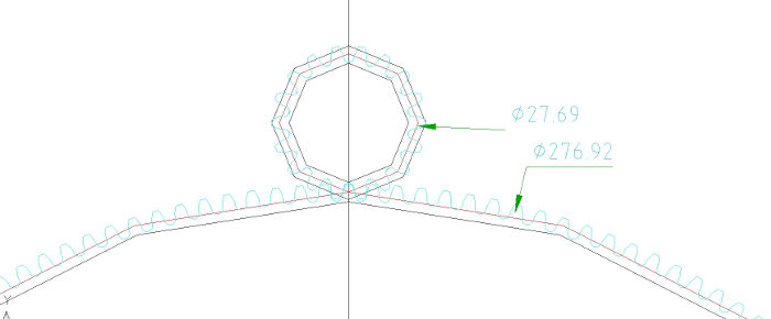
However; we decided to skip it and go on with regular 2 gear mesh system, for this Tanvir had calculated the required Parameters
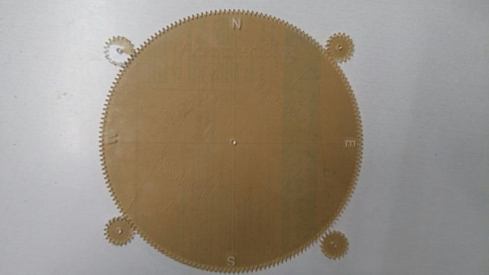
Having set the required Outer Diameterof the driven gear as 280mm,Number of teeth to be 180, Gear ratio to be 0.1 and Diameteral Pitch as 1, and Pressure angle to be 20degrees the following parameters were calculated:
Note # The Driven gear is denoted as 1, and Driving gear as 2 After designing, we couldn't cut the gear from our lab as the laser cutter in our lab was not working. I was anyway traveling to Trivandrum on that week coincidentally. So Tanvir sent the file to me.
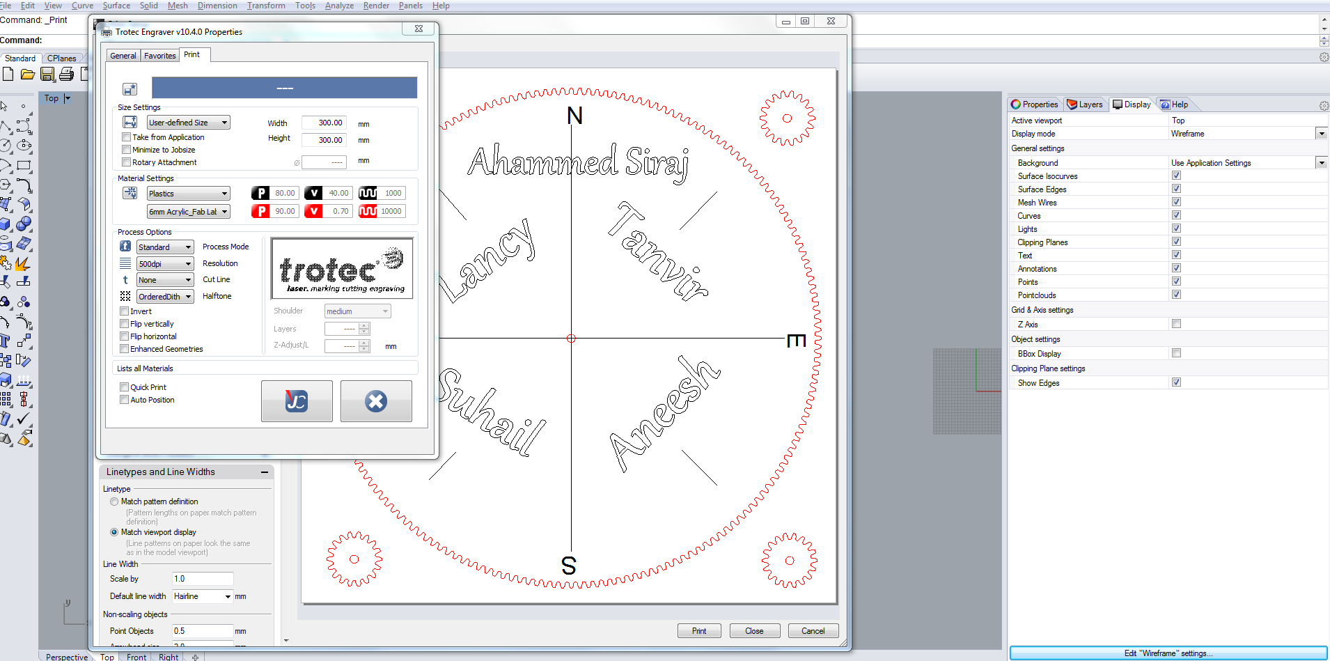
While in Trivandrum I found that the gear can be easily designed in inkscape as well. I didn't know that until this week. We just have to give the parameters and the gear will be ready. No need of going through the strenuous desgining steps :P Unfortunatley Tanvir didn't know it as well and we came to know about that only after the design was made.
Vishnu, the TVM instructor had told me about this feature in inkscape. I just gave it a try afterwards.
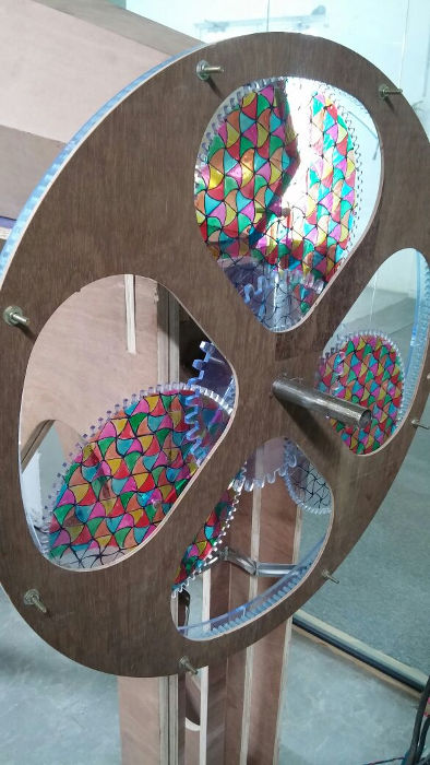
After giving it a try, before laser cutting I decided to engrave the names of the team members.

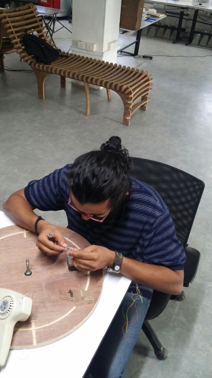
Working on fixing the smaller gears on top of the stepper motor. It was not a perfect fit. Heated the slot using hot air gun and filed it a bit using circular file.
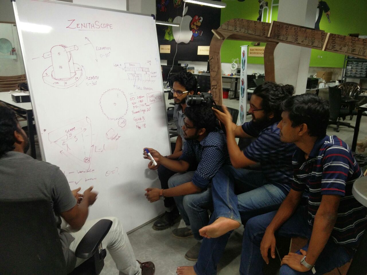
Instructor clearing the doubts B-)
 some fun in between :P
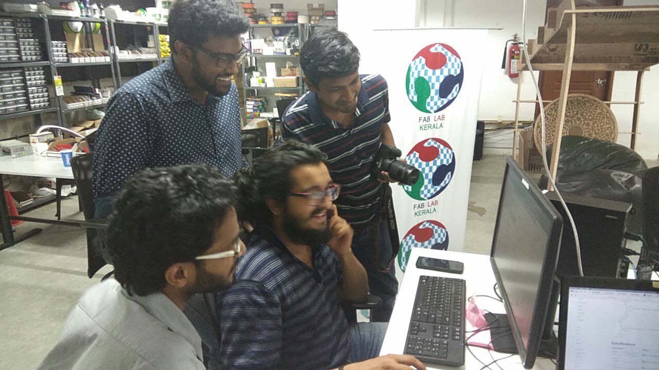
I was documenting the major part of the project and made some mistake in between and everyone was having a laugh as shown in the image :P
< bit too honest ? >
=))
xD
some fun in between :P
I was documenting the major part of the project and made some mistake in between and everyone was having a laugh as shown in the image :P
< bit too honest ? >
=))
xD