   Familiarize microcontroller data sheet.

   Program the board in atleast 2 different programming languages/environments.

   Optionally, experiment with other architectures.
This week we have to program the echo hello world board we made 2 weeks back. LED control using the switch. I don't have programming background so I thought this week was going to be tough. But in the end it was not as difficult as I imagined. Just went through the data sheet of Attiny44 once before programming.
tinyAVR Microcontrollers
Atmel tiny category of microcontrollers are optimized for applications that require performance,power efficiency and easy of use. All tinyAVR devices are based on the same architecture and compatible with other AVR devices.
Attiny 44A is the high performance 8bit AVR RISC based architecture microcontroller by Microchip It is having 4KB ISP flash memory,256 Byte EEPROM, 256B SRAM,12 general purpose I/O lines, 32 general purpose registers,an 8 bit timer/counter with two PWM channels,a 16-bit timer/counter with two PWM channels, internal and external interrupts, an 8-channel 10-bit A/D converter, programmable gain stage (1x, 20x) for 12 differential ADC channel pairs, programmable watchdog timer with internal oscillator, internal calibrated oscillator, and four software selectable power saving modes.The device operates between 1.8-5.5 volts.
" ATtiny24/44/84 is a low-power CMOS. It's an 8-bit microcontroller based on the AVR enhanced RISC architecture. By executing powerful instructions in a single clock cycle, the ATtiny24/44/84 achieves throughputs approaching 1 MIPS per MHz allowing the system designer to optimize power consumption versus processing speed."
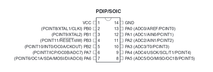
LED in PA7 and switch in PB2
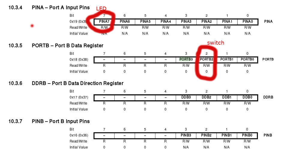
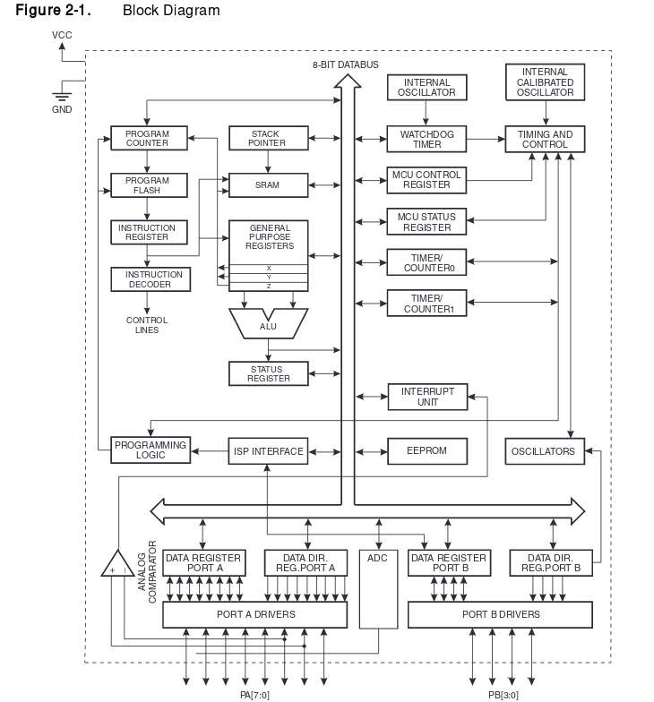 From this I understood PORT A has Analog to Digital Convertor capability but PORT B doesn't.
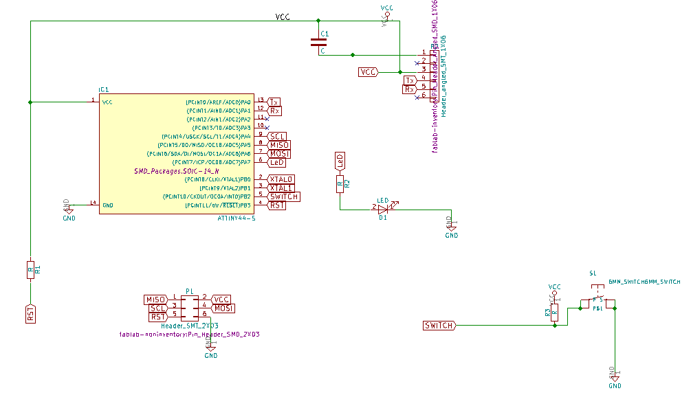
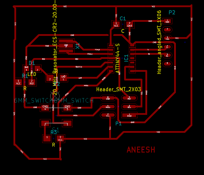
Attaching the schematic and position diagram of my board.
The LED soldered is in PA7 and switch is in PB2.
AVR-GCC compiler
AVR-GCC is a compiler that takes C language high level code and creates a binary source which can be uploaded into an AVR micro controller. Thus AVR-GCC might be regarded as a 'C' cross compiler for producing AVR code. Once code in 'C' is written for a particular project AVR-GCC will turn C code into assembly language files. AVR-libc includes all the header files that contain the addresses of port and register names. Individual assembler files are then converted into object files. Object files are files of code that AVR chips could run. The linker AVR-ld will take all these assembler files, and cross-reference functions names to create one single object file. The linker will also take modules from the 'C' library and make them into a single object. Normally this linked object is in ELF format and furthermore AVR-objcopy is used to generate a HEX format file. The hex file can be flashed to the chip using programmer. The above mentioned details are simply depicted below.
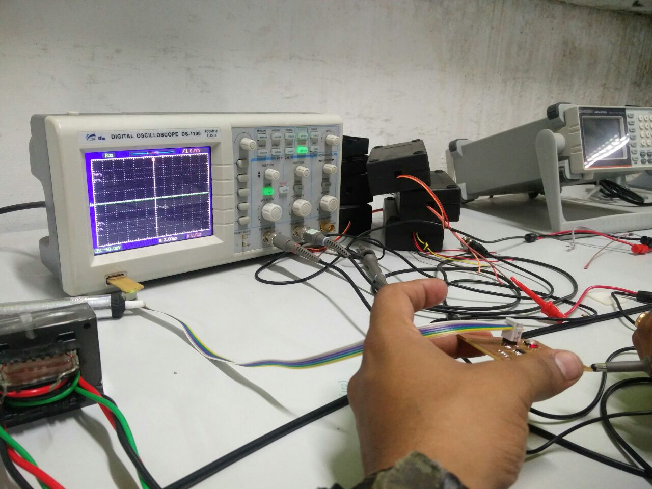
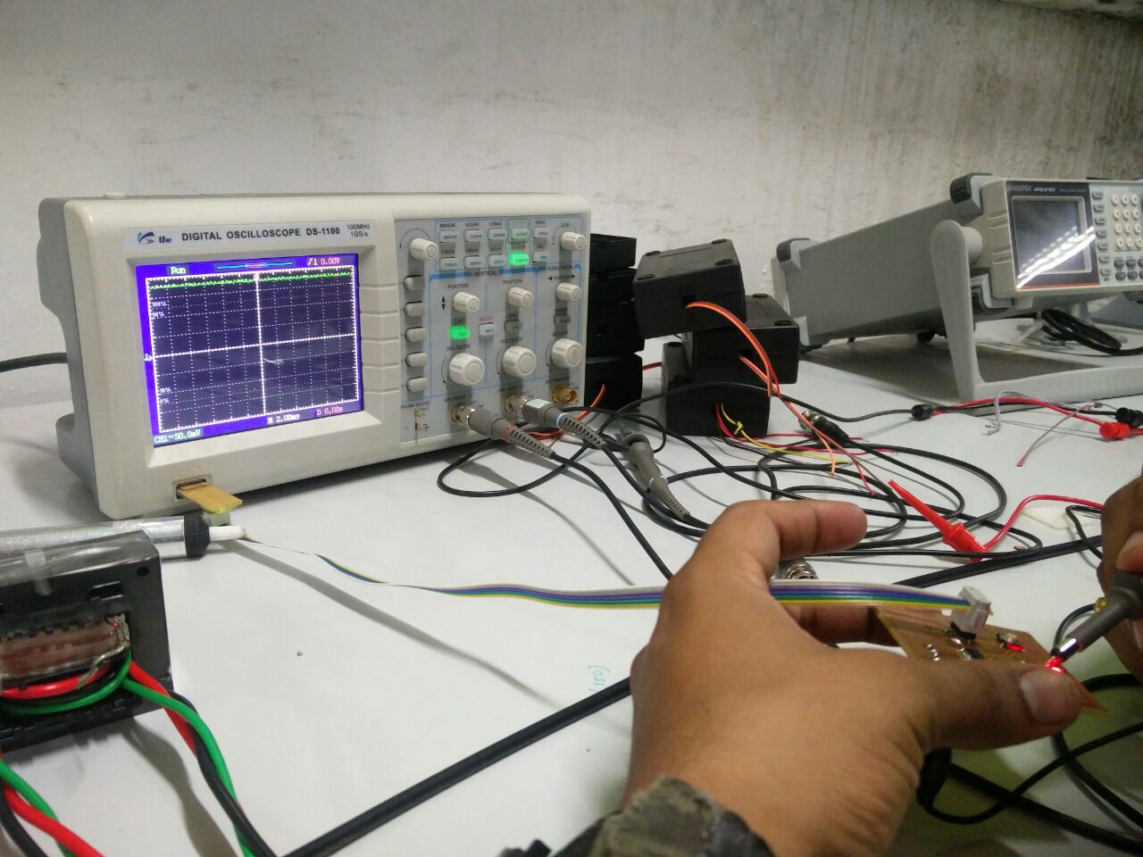
This week I was in Trivandrum fab lab as I had to go to Trivandrum to attend a function and had a few personal stuff to take care of. Yadu and Vishnu helped a lot especially the programming part.
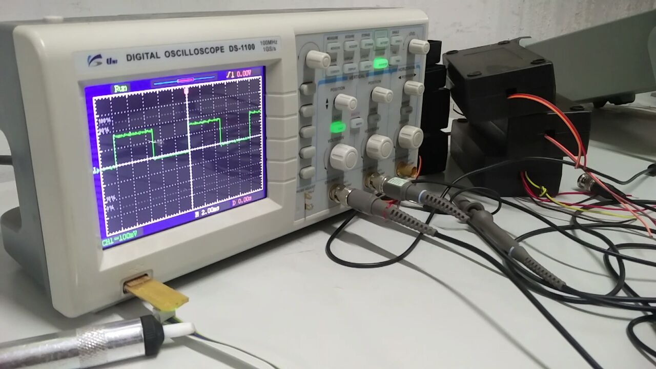
Firstly checked if the boards were working. The program can be written in IDE's(Integrated Development Environment), there are different varieties of IDE are available, I used Atom. Then I tried Arduino IDE.
This program is written in embedded C programming language. Actually the microcontollers will understand mechine level languages(binary), it is a low level language and hard to understand, that's why we are using highlevel languages like "C". The programs will be written in C language and saved with extension ".c". Inorder to run this program on microcontroller we may need to conver the high level langauges to low level language. Inorder to convert high level language to machine level language a Compilers/ Interpreters is required. These two are having differences, we are using compilers to convert our C program to machine level language. The compiler used here is "AVR-GNU Compiler Collection"(AVR-GCC), GCC supports C-code compilation, some debugging may be required while compiling, once you compiled successfully we will get a ".hex" file , that is the machine level code equivalent to our C program. Next we have to flash the program into the microcontroller, for that we require AVRDUDE - AVR Downloader Uploader - is a program for downloading and uploading the on-chip memories of Atmel’s AVR microcontrollers. It can program the Flash and EEPROM, and where supported by the serial programming protocol, it can program fuse and lock bits. Using Avrdude we can fuse the microcontrollers with the help of a programmer. Avr dude supports different programmers, here i used my Fab ISP as the programmer.
Inorder to compile in avr-gcc and flash the program on attiny44, we may need to run certain commands from the terminal.
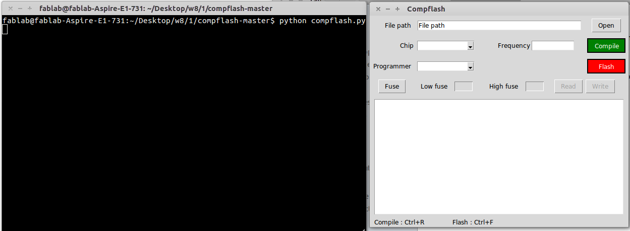
Yadu of fablabtrivandrum developed one User Interface in python language for easy compiling and flashing, it's called Compflash. Its available in the here. I cloned it to the PC. It requires certain dependancies, you can install it in your PC using commands. Once cloned,open terminal from the cloned directory, then type python compfalsh.py. It will open the GUI of comp flash like this.
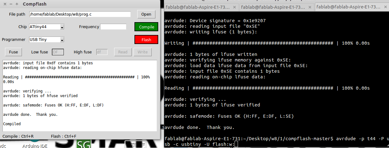
Next select the file from the directories, select chip,its frequency,and the programmer. I have selected selected my file from the folder, selected chip as ATtiny44 ,frequency as 20MHz and programmer as USB Tiny. Then i pressed the compile button, at first some syntax errors were there so it showed the error, later i corrected the program and compiled once again and this time it successfully compiled and is shown below.
Blinking the LED with one second delay.

#include<avr/io.h>  // importing avr/io library
#define F_CPU 20000000  // defining CPU speed as 20MHz
#include<util/delay.h>  // importing delay library

main()
{
DDRA = 0xff;        // set data direction register to 0b11111111
while (1)
{

PORTA|=(1<<7);      // set PA7 High
_delay_ms(1000);    // setting a delay
PORTA&=(!(1<<7));   // set PA7 Low
_delay_ms(1000);    // setting a delay
}
}
The program can be downloaded here.
Blinking the LED by using a switch

#include <avr/io.h>
#define F_CPU 20000000
#include <util/delay.h>
#include <avr/interrupt.h>

main ()

{

    DDRA= 0x0FF;
    DDRB= 0xF;

PORTB|=(1<<2);

    while(1)
    {
        if (!(PINB&(1<<2)))
        {
            PORTA|=(1<<7);
        }
        else
        {
            PORTA&=(!(1<<7));
            }

    }
}
The program can be downloaded here.
Arduino is an open-source platform used for building electronics projects. Arduino consists of both a physical programmable circuit board (often referred to as a microcontroller) and a piece of software, or IDE (Integrated Development Environment) that runs on your computer, used to write and upload computer code to the physical board. There are a large collection of tutorials are available on Arduino, out of which ,I found the following tutorial is good to know more about Arduino.
Connect the hello world board to the FabISP using FTDI cable.
Arduino IDE was already there in my PC. The Programming was done here.
By default, The attiny board wont be present in Arduino. You either have install the borad files or paste the ATtiny files into t he arduino directory.To install the files, select
tools>board>boards manager
In the bottom of the boards menu, there is an option to install the attiny by David A. mellis.
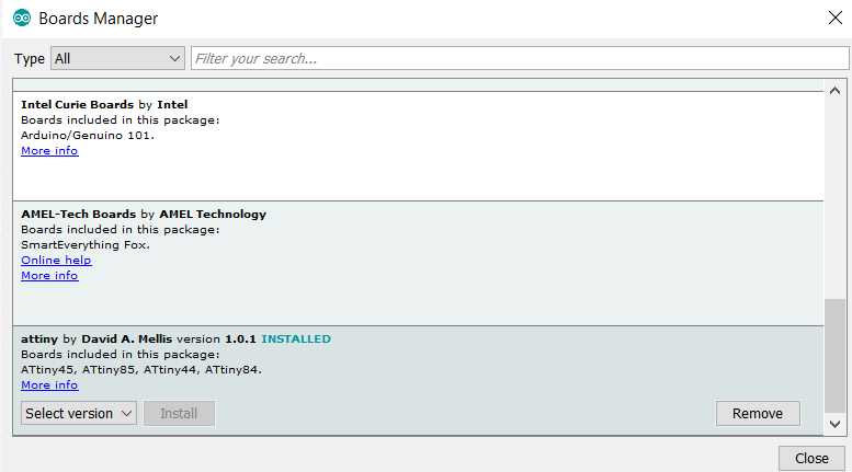
Install it and the then select the Attiny from board.
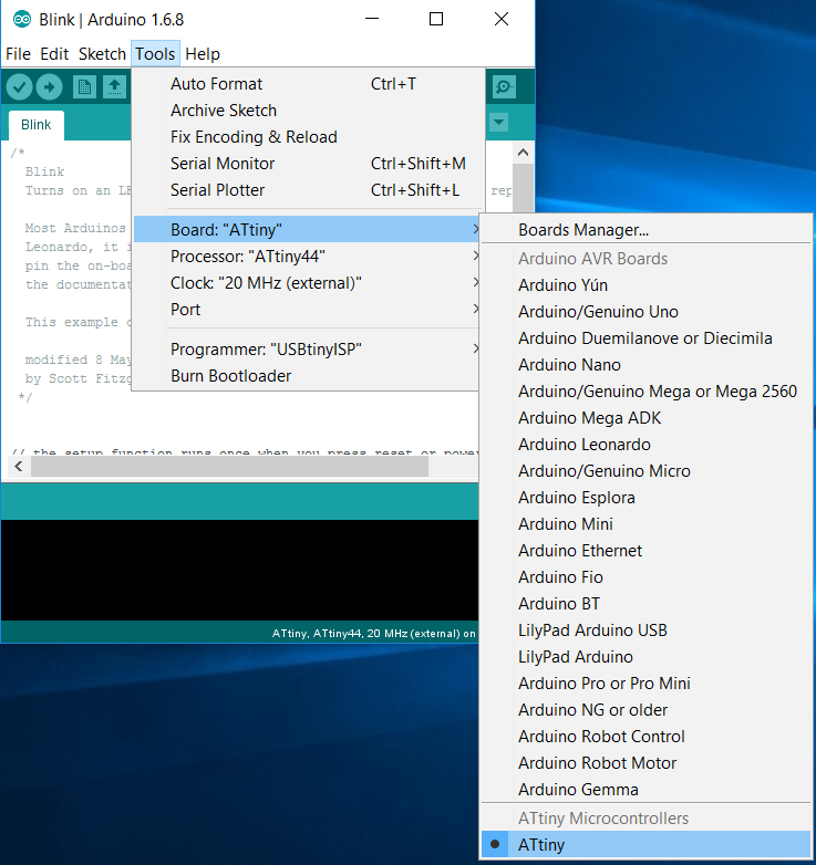
select the processor in tools menu. In my case - Attiny44A.
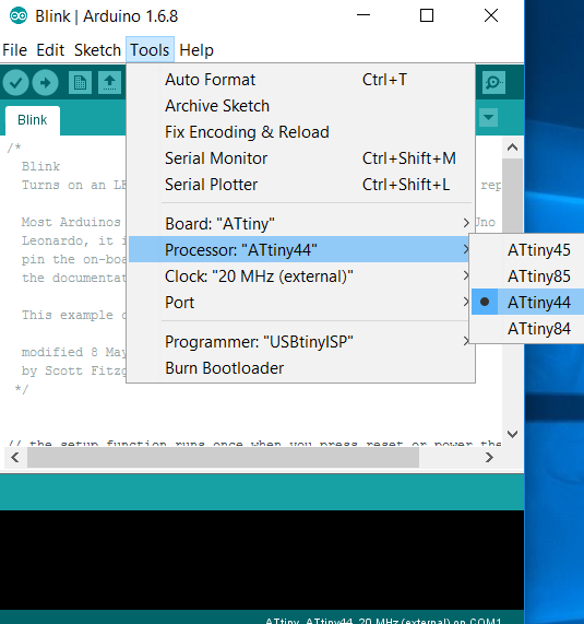
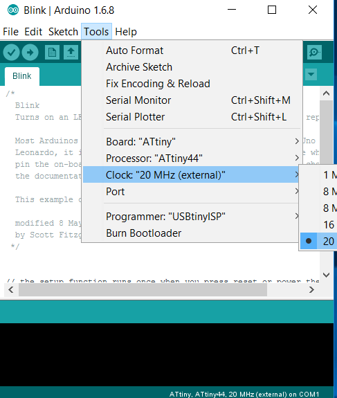
Select the clock (I chose 20MHz)
Now, we have to select the programmer used for programming the board. I used FabISP we made during the electronic production week,so I selected the USBtiny programmer.
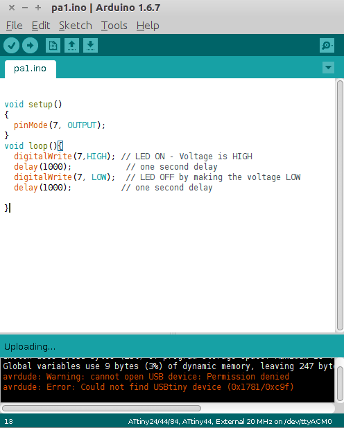
It was showing an error at first while compiling.
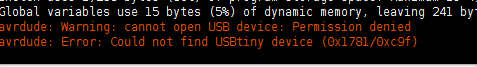
This was fixed when I used sudo command to open the Arduino IDE.
The program can be downloaded here.