Week 7 - COMPUTER CONTROLLED MACHINING

Assignment

    Make something big

Computer Controlled Machining

CNC router (Or Computer Numerical Control router) is a computer-controlled cutting machine related to the hand held router used for cutting various hard materials, such as wood, composites, aluminium, steel, plastics, and foams. CNC stands for computer numerical control. CNC routers can perform the tasks of many carpentry shop machines such as the panel saw, the spindle moulder, and the boring machine. They can also cut mortises and tenons. A CNC router is very similar in concept to a CNC milling machine. Instead of routing by hand, tool paths are controlled via computer numerical control. The CNC router is one of many kinds of tools that have CNC variants. A CNC router typically produces consistent and high-quality work and improves factory productivity. Unlike a jig router, the CNC router can produce a one-off as effectively as repeated identical production. Automation and precision are the key benefits of cnc router tables. ~ Wikipedia

Controlling the Machine

The CNC router is controlled by a computer. Coordinates are uploaded into the machine controller from a separate CAD program. CNC router owners often have two software applications—one program to make designs (CAD) and another to translate those designs into a 'G-Code' program of instructions for the machine (CAM). As with CNC milling machines, CNC routers can be controlled directly by manual programming, and CAD/CAM opens up wider possibilities for contouring, speeding up the programming process and in some cases creating programs whose manual programming would be, if not truly impossible, certainly commercially impractical. ~ Wikipedia

Design

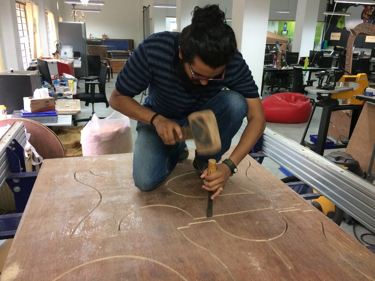
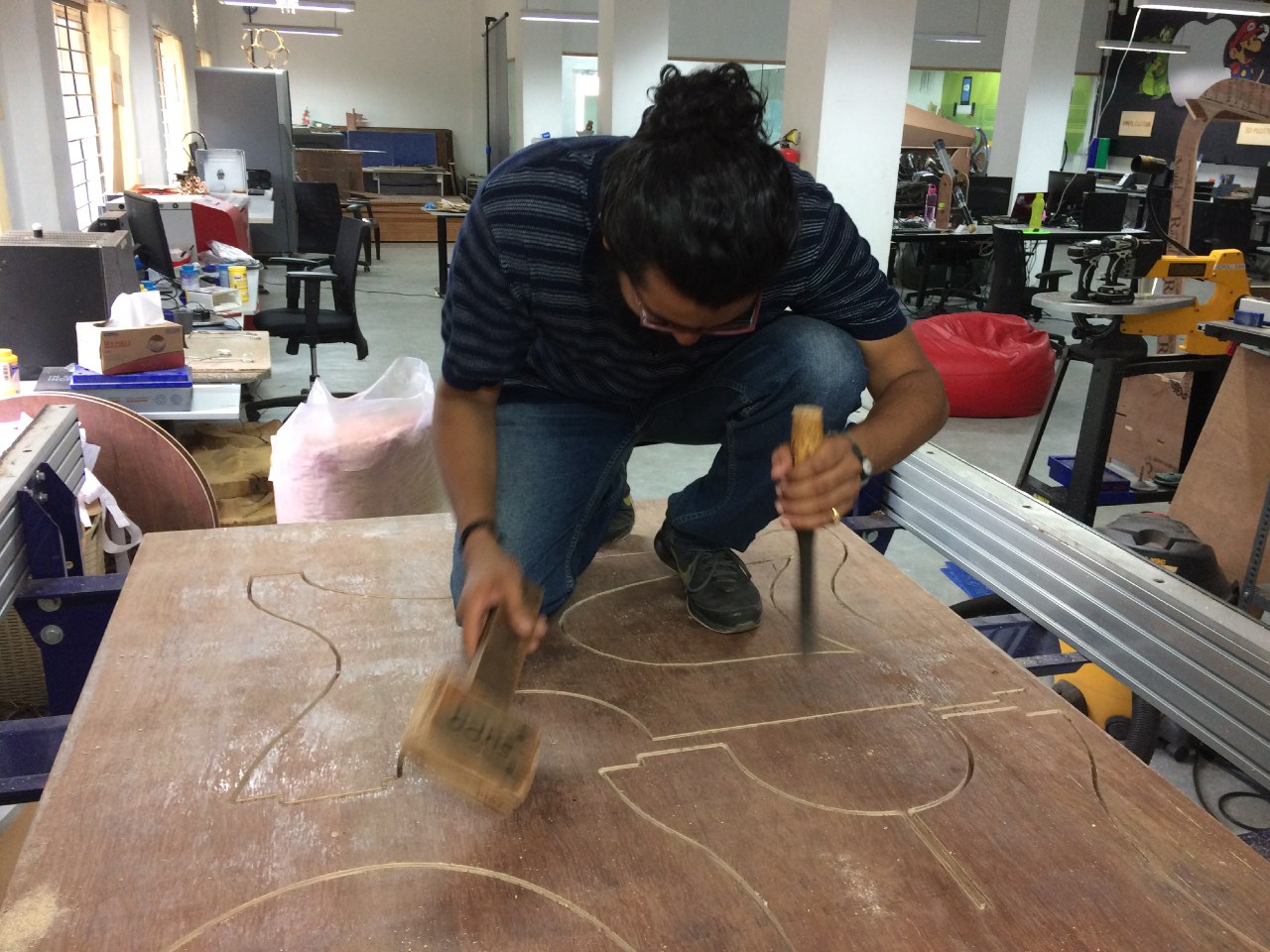
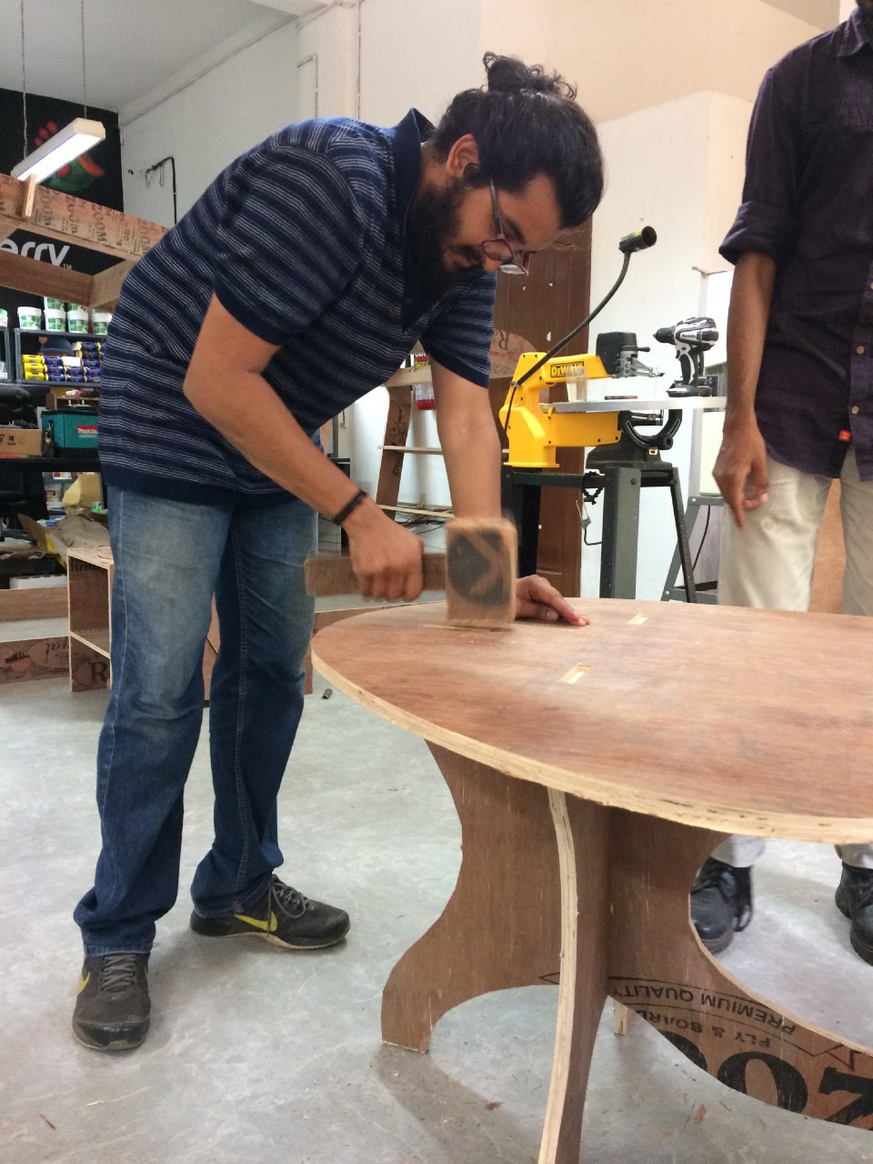
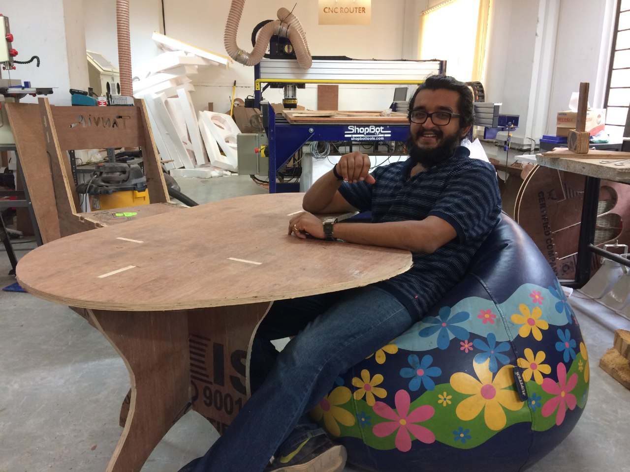
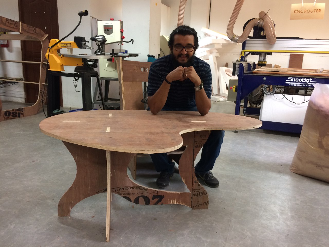
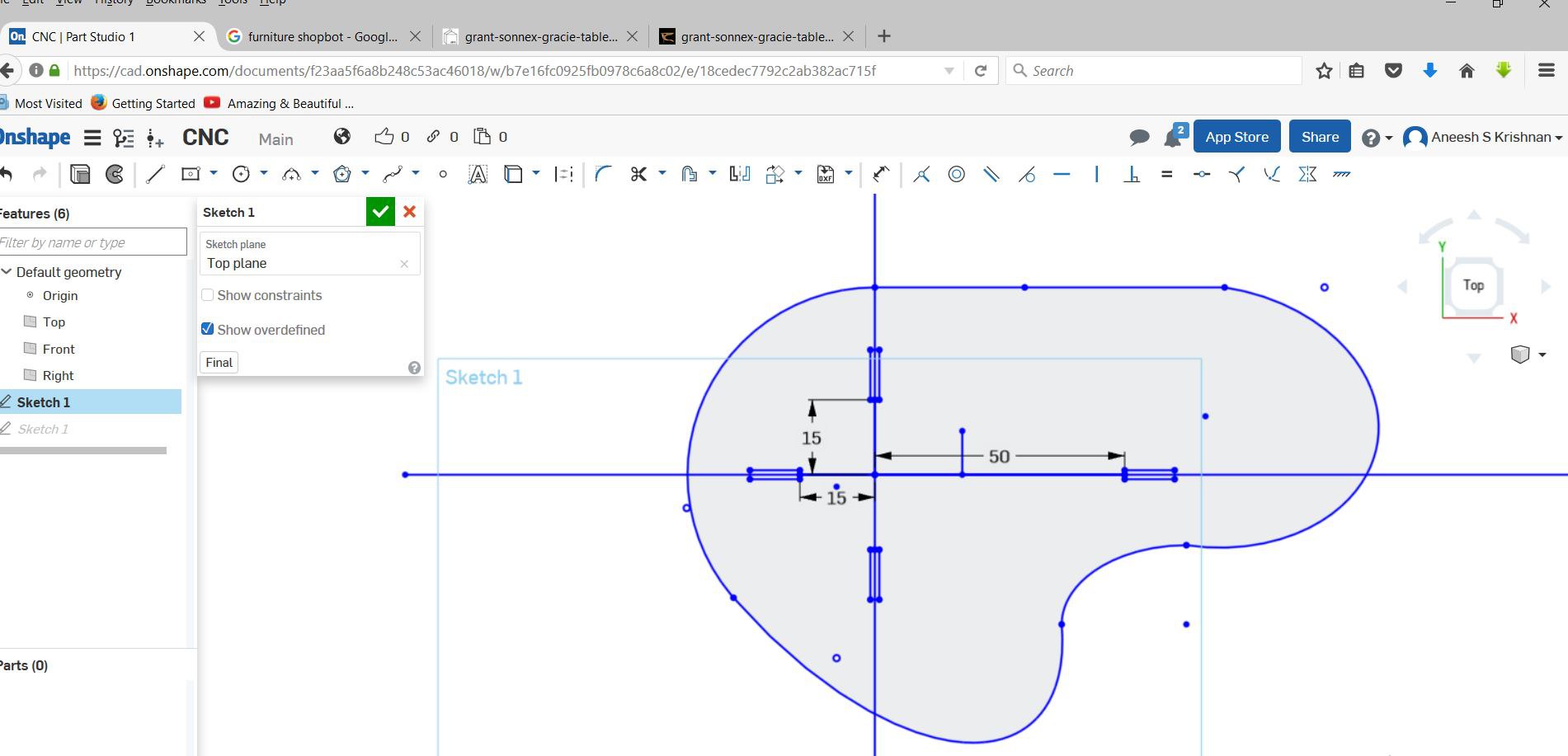
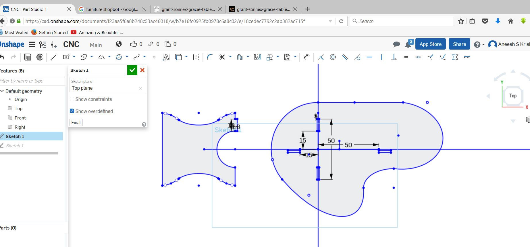
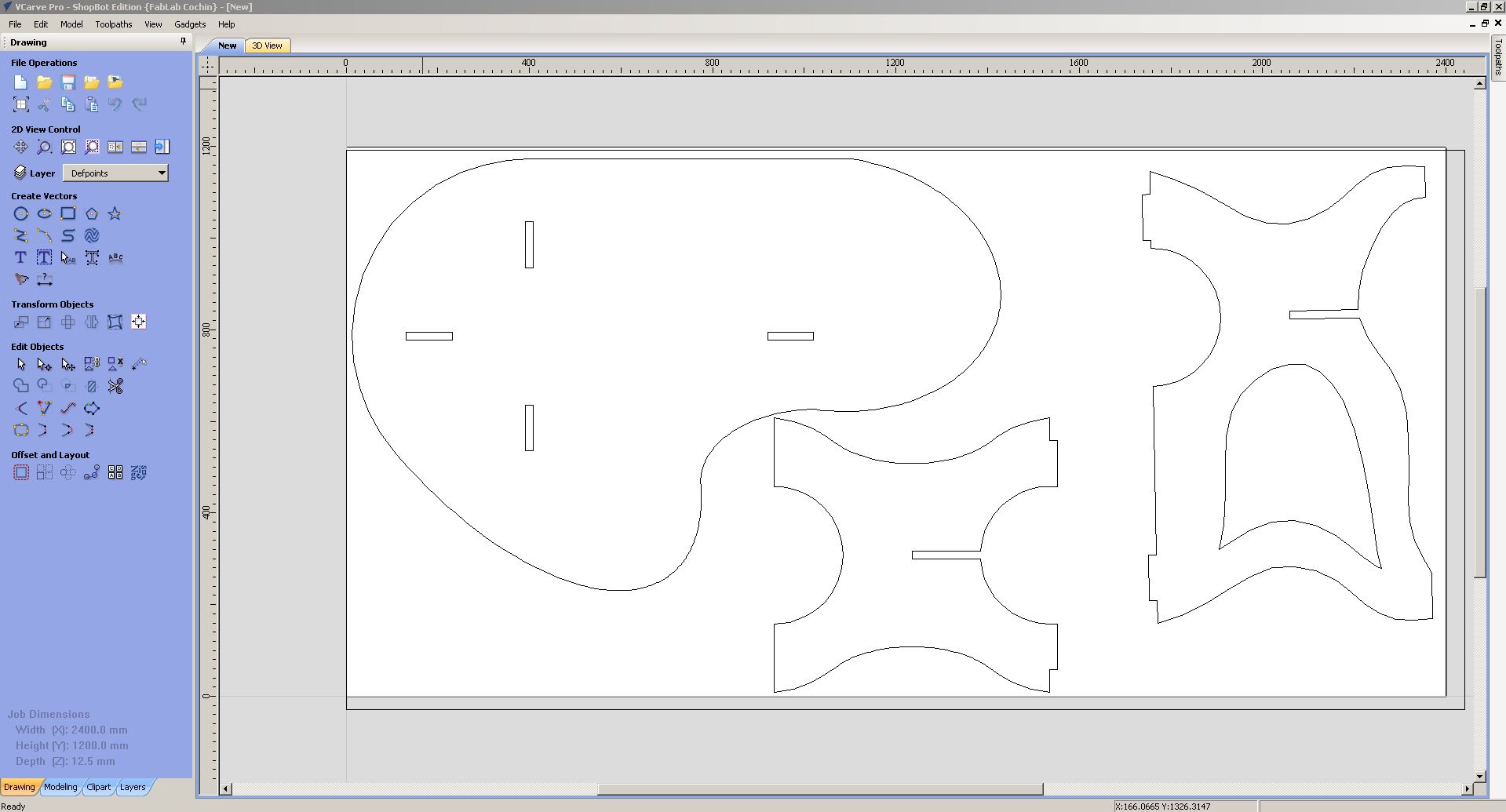
I tried Onshape this week. Decided to make a small table.

The design files can be downloaded here.


Measuring the material

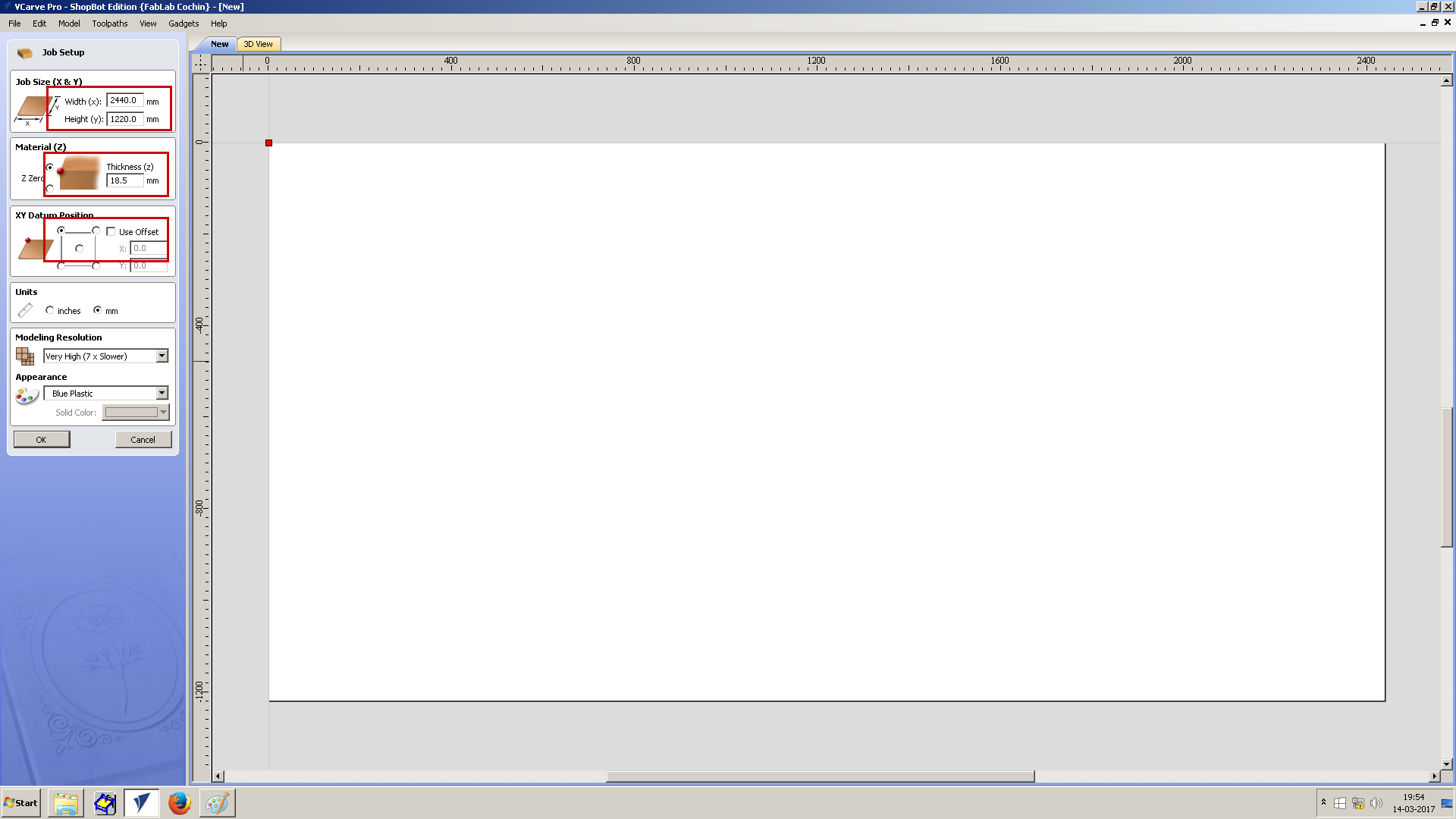
To get an accurate measure of the plywood, I measured the plywood at many places, to get a homogeneous measure. I found that the values were ranging from 16mm to 20.5 mm.
For desining Thickness, Mill bit diameter,Clearance gap are the required parameters. 
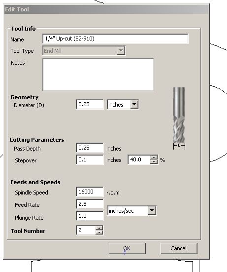
The Mill bit I would be using is a 1/4" bit. As it would give me a balance between feed rate and diameter of cut. Also, the clearance gap was calculated as .7 cm minimum, as .635 cm would be the cut diameter. 
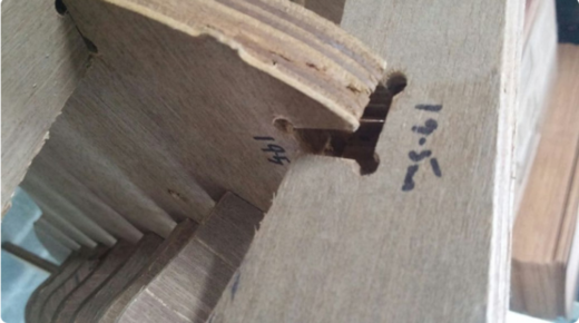
The fit between the male and female joints needed to be found, for this I used some old joint that were aldready made.


With a 19.5 mm fit between the joints, the fit was loose, and would easily come out by just pulling the joint. And since I wanted a table the fit had to be tight. For, this I checked other sample, which had 18 mm male and female joint, with this specification ,the fit was tight, and the one I would be using. As the plywood has different thickness on its surface, the 18mm joint would fit it most point, except some places where the thickness drops to 17 mm.


I designed and assembled the table in onshape and this is the sketchfab model.

Cnc by aneeshskrishnan on Sketchfab


Operating Shopbot

Guidelines to follow
Wear the gloves, eye protection glasses and noise cancellation headset when we are operating the machine. Compressor should be ON before start operation. Never leave the machine unattended. Quickly press emergency stop button in case something goes wrong. Make sure drill-bit wont touch screws or clamp. Put enough tabs Operating ShopBot includes mainly two sections.

1. Generate required files using Vcarve Software

Vcarve software is used for arranging each elements to be cut and to generate files which are to be fed into ShopBot's application. Each parts to be cut are arranged such that plywood wastage is minimum. Following steps were used to generate required .sbp file. Open the software and create a new file. Select required plywood size, material thickness and origin position. I used the following settings. 2440x1220mm size 18.5mm thickness Top left corner as origin point


Now, the major options I used are

1. Drawing circle. I used it for marking drilling holes for using screws.
2. For changing size of object.
3. To rotate object at particular angle.
4. Take mirror image of the selected object.
5. To select an object.
6. To group each objects as a single element.
7. To ungroup a grouped object.
8. To join each vectors in an element.


Import each part designs into Vcarve.
Follow this => File -> Import -> Import vector file.
Files were imported and arranged as below.

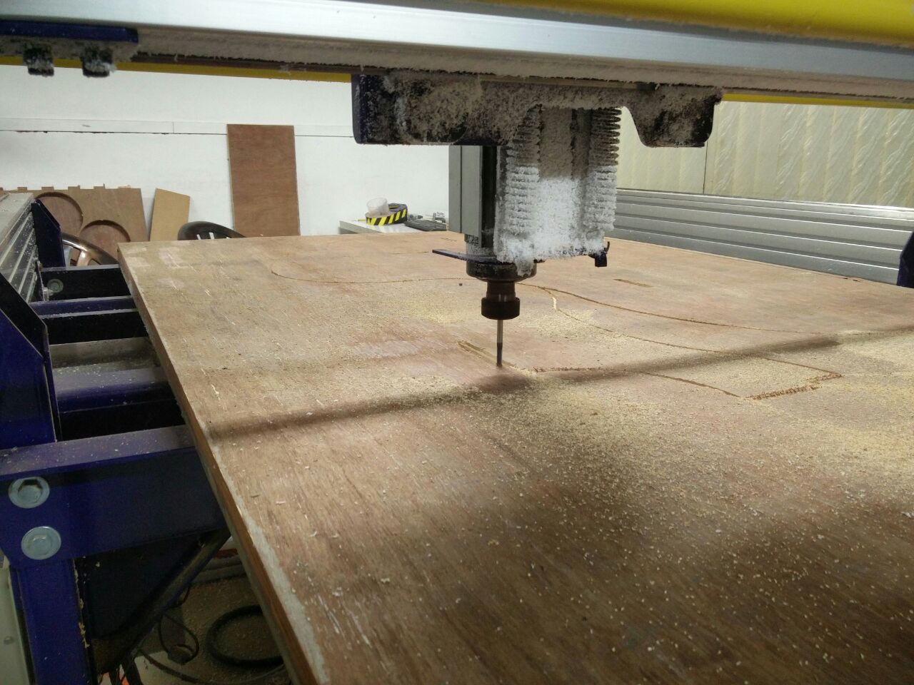
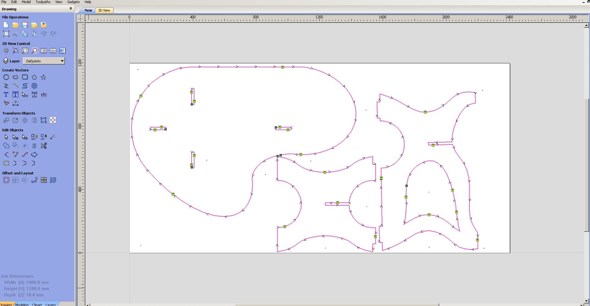
On the right side there is toolpath settings menu. First button under Toolpath Operations Tab is Profile Toolpath, this is used to set the profile settings for cutting the plywood. Third tab under the same section is Drilling Toolpath, this is used for setting drill holes. I used the following settings in Profile Toolpath.


  1. Cut Depth - 18.5mm

  2. Tool
1/4" Up-cut Spindle Speed - 16000 rpm Feed Rate - 0.5 inches/sec Plunge Rate - 1 inches/sec Pass Depth - 0.25 inches Cut type - Outside
I made a mistake in the above instruction. I gave the cut depth as 0.25 initially. This resulted in breaking of the bit. Then I changed the Pass depth to 0.125 inches
  • Tabs of 3mm thickness is provided in the table.

  • After setting this in toolpath menu, click the calculate button to generate the toolpath. Also, Select 3D view tab to get 3D view of the object.


    This profile is then saved as .sbp file. For saving, select save button from Toolpath menu available on the right side. Now a profile file for shopbot is created. But, to fix the wood strongly we have to use screws. For this, screw positions were selected and used circle tool to mark it on board. Circle of diameter 8mm were used. For drilling path file, I used the following setting. Cut Depth - 1mm Tool - 1/4" Up cut
    Now both profile and drill files are ready.

    Start Cutting

    Now, once the Gcode file is created, it has to be send to the ShopBot. For setting up the Shopbot, Fix the required bit in the machine.

    Open the shopbot application.


    The button with a yellow background is used to open keyboard which is used to move the machine to required position.


    Use this keyboard to set a origin point. After moving the head to required origin point click on the orange background colored button named Fixed and select X and Y. Then click on button named zero.


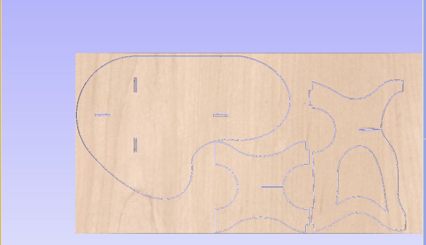
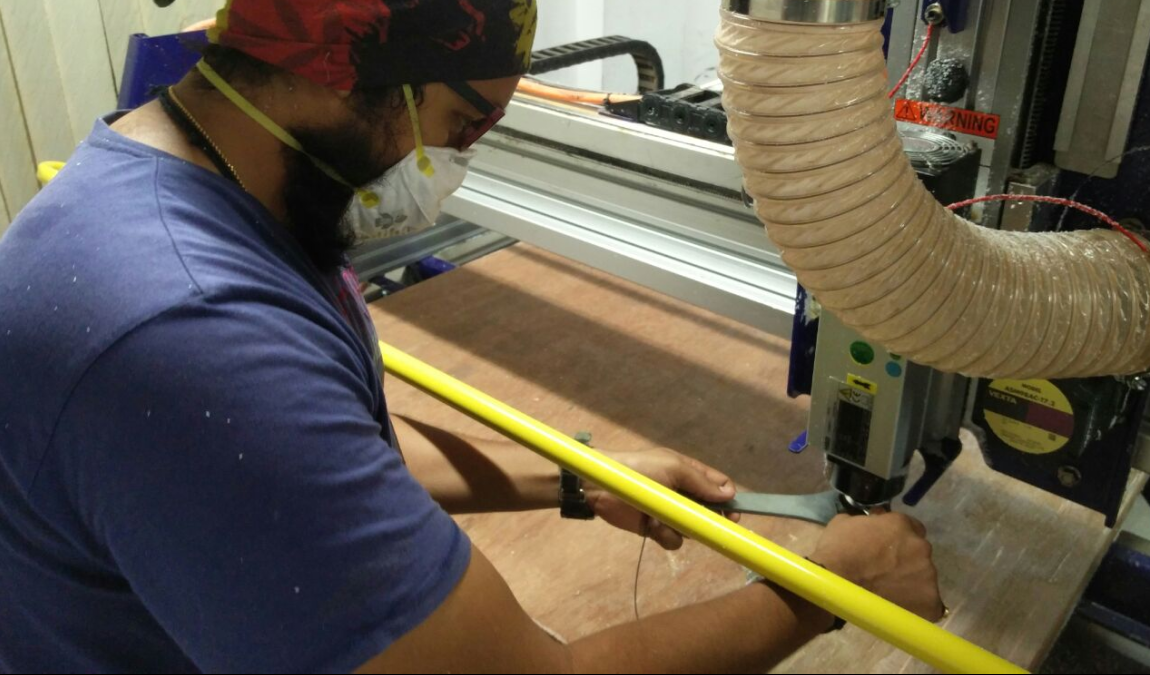
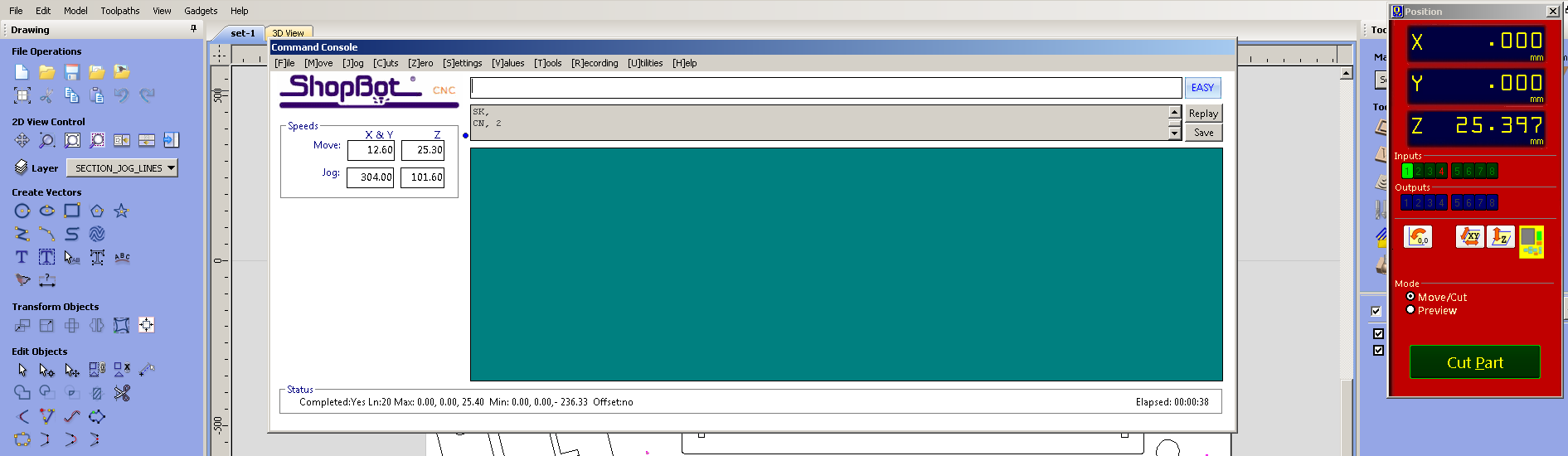
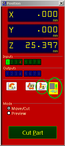
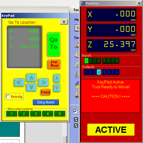
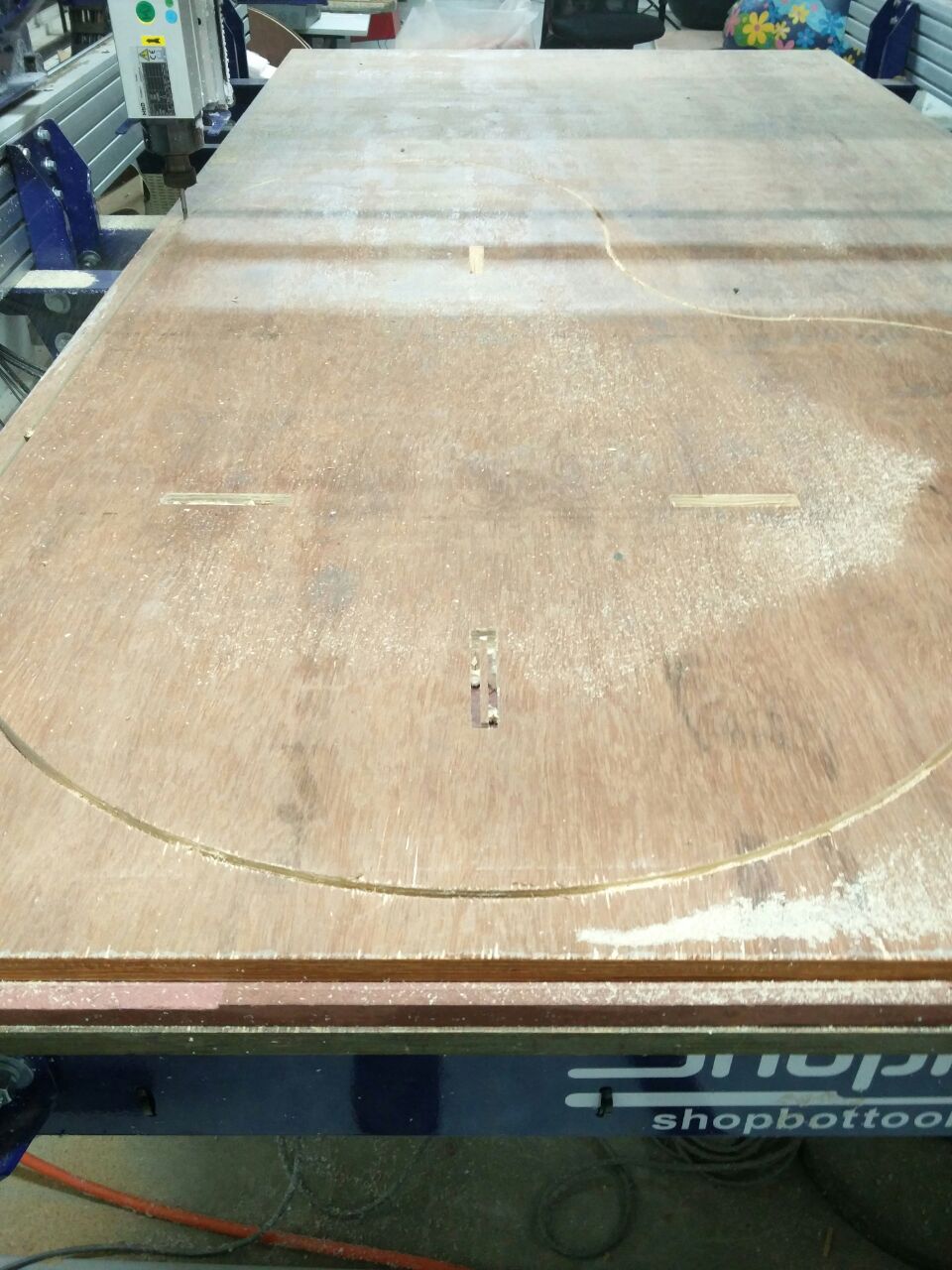
    Now we have to set the z axis. For this we have to place the plate below the drill bit & cick on the button left to the keyboard icon. Now,turn on the machine. Click on the Cut Part button button and choose drill toolpath file first. Press the spindle start button when the pop up window ask to do so. And click OK. Then the machine will start drilling. Put screws on these holes. And select profile toolpath file for cutting the plywood.


    Assembling


    Hero Shots :P


    Problems Faced

  • 1

  • Initially I had the following parameters
    1/4" Up-cut
    Spindle Speed - 16000 rpm
    Feed Rate - 0.5 inches/sec
    Plunge Rate - 1 inches/sec
    Pass Depth - 0.25 inches
    Cut type - Outside

    The problem with this was , instead of 0.25 I should've given only half its value; i.e, 0.125! Since this was wrong, a "not so normal" noise was coming out from the machine. I didn't know this was a problem until the bit BROKE!! So I stopped the machine immediatley. Changed the pass depth to 0.125 and used the same bit to cut the rest of the wood as it was still usable.


  • 2
  • The second problem was that I tightened the collet very tightley and I couldn't remove it when the bit broke. So we had to put some oil on the collet section as it will lubricate that part. I tried loosening it after a few minutes and finally it came off.

    Design Files

  • Table Design - Download