. Test the limits for your 3D-printer (group project)
. Design & 3D print an object (small,few cm) that cant be made subtractively
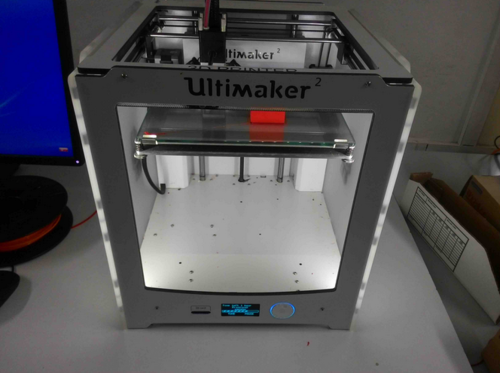
. 3D scan an object (and optionally print it)Ultimaker 2 is capable of printing objects with PLA (Polylactic Acide) material.
Layer resolution: up to 20 µm Build volume: 23 cm × 22.5 cm × 20.5 cm Position precision X Y Z: 12.5 µm × 12.5 µm × 5 µm Print speed: 30–300 mm/s Travel speed: 30–350 mm/s Filament diameter: 2.85 mm Nozzle diameter: 0.4 mm Card support: Stand-alone SD-card printing Feature: WiFi printing ready (future upgradeable) Software: Cura - Official Ultimaker Print technology: Fused filament fabrication (FFF) Frame dimension X Y Z: 35.7 cm × 34.2 cm × 38.8 cm (no filament) Frame dimension X Y Z: 49.2 cm × 34.2 cm × 55.8 cm (with filament) Operation nozzle temperature: 180-260 °C Operation heated bed temperature: 50-100 °C AC input: 100-240 V/~4 A/50–60 Hz/221 watt max. Power requirements: 24 V DC @ 9.2 A
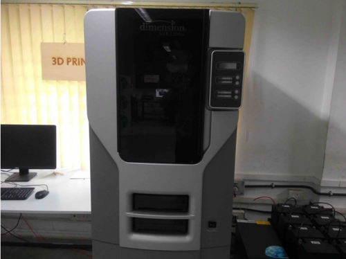
Dimension SST 1200es 3D printer uses ABS (Acrylonitrile Butadiene Styrene) as the model material and SST as support material.
Model material: ABS plus in ivory, white, black, red, olive green, nectarine, fluorescent yellow, blue or gray Support material: Soluble Support Technology (SST) or Breakaway Support Technology (BST) Build size: 254 x 254 x 305 mm (10 x 10 x 12 in) Layer thickness .254 mm (.010 in) or .330 mm (.013 in) of precisely deposited ABS plus model and support material Workstation compatibility: Windows XP/Windows 7 Network connectivity: Ethernet TCP/IP 10/100Base-T Size and weight: 33 x 29 x 45 in, 148 kg Power requirements: 220–240 VAC 50/60 Hz
ABS - Its strength, flexibility, machinability, and higher temperature resistance make it often a preferred plastic for engineers, and professional applications.
PLA - The wide range of available colors and translucencies and glossy feel makes it best for for display or small household uses, the plant based origins and the semi-sweet smell has got the advantage over ABS . When properly cooled, PLA seems to have higher maximum printing speeds, lower layer heights, and sharper printed corners. Combining this with low warping on parts make it a popular plastic for home printers.
This is the group assignment for the week.
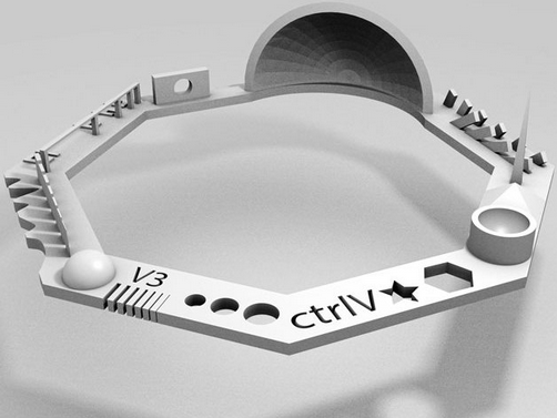
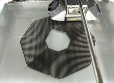
We printed a popular test pattern from thingiverse.
The tests that this object does are:
Nut, Size M4 Nut should fit perfectly
Wave, rounded print
Star, Sharp Edges
Name, Complex Shapes
Holes, Size 3, 4, 5 mm
minimal Distance: 0.1, 0.2, 0.3, 0.4, 0.5, 0.6, 0.7 mm
Z height: 0.1, 0.2, 0.3, 0.4, 0.5, 0.6, 0.7, 0.8, 0.9, 1.0, 1.1 mm
Wall Thickness: 0.1, 0.2, 0.3, 0.4, 0.5, 0.6, 0.7 mm
Bridge Print: 2, 4, 8, 16 mm
Sphere, Rounded Print 4.8mm height
Sphere Mix, 7 mm height
Pyramide, 7 mm height
Overhang: 25, 30, 35, 40, 45, 50, 55, 60, 65, 70°
Warp, does it bend?
3D Print Font, optimized for 3D printing
Surface, Flatness
Size, 100 x 100mm x 23.83 (10mm width)
Spike, minimum Layer Time, 21 mm height from Bottom (include Baseplate)
Hole in Wall, 4 mm diameter, check for proper print
Raft Test, raft should be just under the model
Retract Travel, check retract settings for longer travel
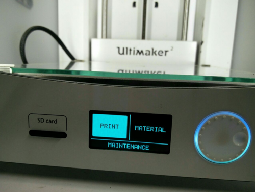
Copied the model to the SD card and inserted it inside the machine.
The menu appeared and we selected PRINT.
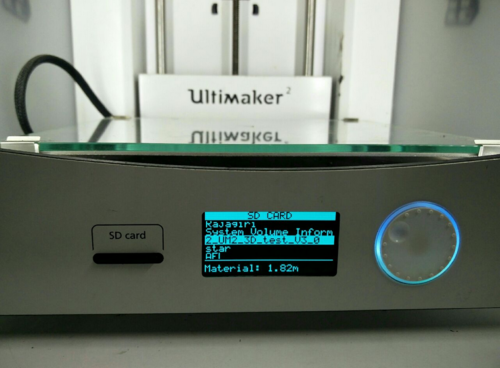
After selecting the Menu, the file was selected.
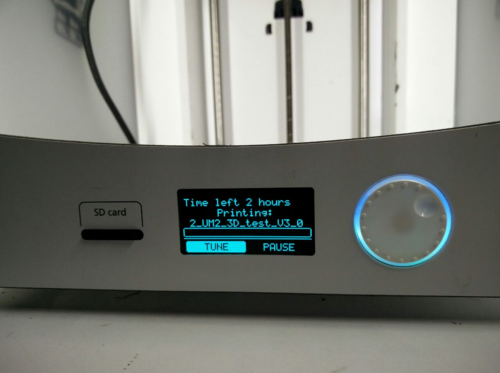
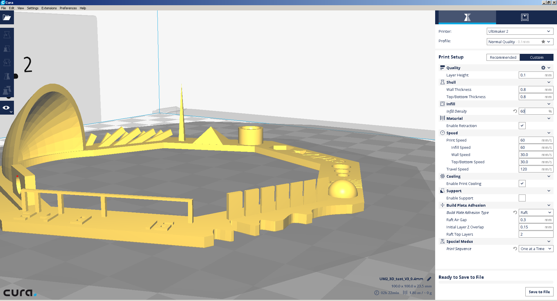
The setting used were:
SPEED:100 mm/s INFILL SPEED:100 mm/s WALL THICKNESS SPEED:40 mm/s TOP/BOTTOM SPEED: 40 mm/s TRAVEL SPEED: 200 mm/s SUPPORT:RAFT AIRGAP:0.2 mm INITIAL Z OVERLAP:0.1 mm RAFT TOP LAYER: 2 LAYER HEIGHT:0.1 mm WALL/TOP/BOTTOM THICKNESS:0.8 mm INFILL: 30% RETRACTION:6.5 mm
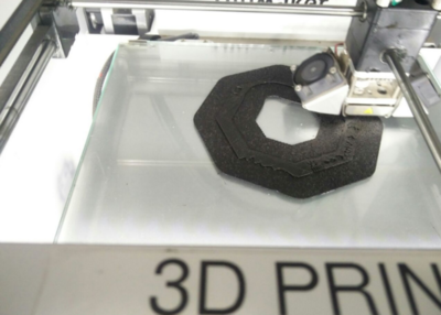
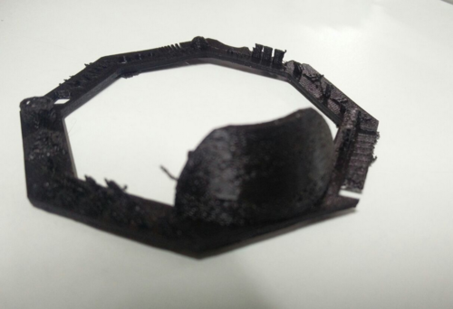
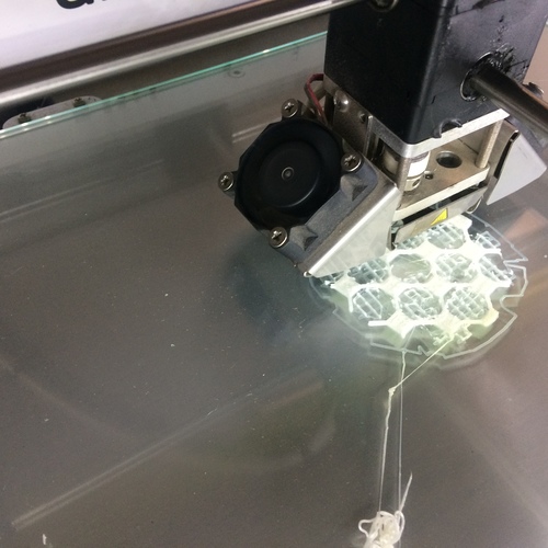
As you can see from the result above that the model has a lot of errors , like webbing and incompletness.
The base of the dome structure has many holes, this may be caused due to retraction being high, from the adjacent structure.
The setting used were:
SPEED:100 mm/s INFILL SPEED:100 mm/s WALL THICKNESS SPEED:40 mm/s TOP/BOTTOM SPEED: 40 mm/s TRAVEL SPEED: 200 mm/s SUPPORT:RAFT AIRGAP:0.2 mm INITIAL Z OVERLAP:0.1 mm RAFT TOP LAYER: 2 LAYER HEIGHT:0.1 mm WALL/TOP/BOTTOM THICKNESS:0.8 mm INFILL: 30% RETRACTION: 2 mm
Here we decreased, the retraction from the default 6.5 mm to 2 mm, to counter the effects , as we saw in the previous trial.
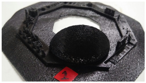
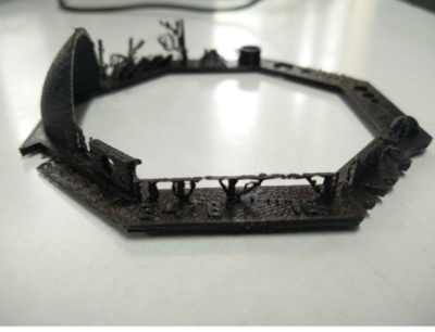
As you can see from the result above that the base of the dome ,even though improved from the previous trial, still has the holes.
The retraction needs to be reduced even more.
The setting used were:
SPEED:100 mm/s INFILL SPEED:100 mm/s WALL THICKNESS SPEED:40 mm/s TOP/BOTTOM SPEED: 40 mm/s TRAVEL SPEED: 200 mm/s SUPPORT:RAFT AIRGAP:0.2 mm INITIAL Z OVERLAP:0.1 mm RAFT TOP LAYER: 2 LAYER HEIGHT:0.1 mm WALL/TOP/BOTTOM THICKNESS:0.8 mm INFILL: 30% RETRACTION:1.5 mm
Here, we have decreased the retraction even further.
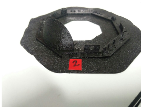
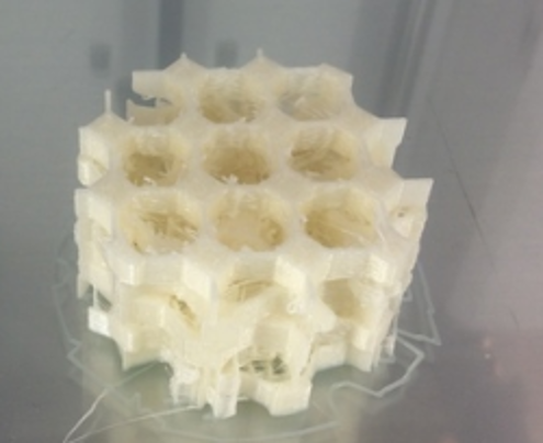
As you can see from the result above that the model still has the incompletness issue at various locations.There is also lot of webbing in the inverted hemispherical area.
Also, the bridge isnt properly completed.This may be due to less infill rate.
The setting used were:
SPEED:100 mm/s INFILL SPEED:100 mm/s WALL THICKNESS SPEED:40 mm/s TOP/BOTTOM SPEED: 40 mm/s TRAVEL SPEED: 200 mm/s SUPPORT:RAFT AIRGAP:0.2 mm INITIAL Z OVERLAP:0.1 mm RAFT TOP LAYER: 2 LAYER HEIGHT:0.1 mm WALL/TOP/BOTTOM THICKNESS:0.8 mm INFILL: 60% RETRACTION:0 mm
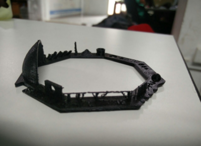
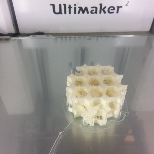
Here we have completely removed the retraction, and given a 0 mm value for it.Also the fill rate has been increased to counter the incompltness at some sites.
The incompletness of the bridge and the base of teh dome is also resolved.
The webbing inside the inverted hemisphere is also absent
The model, now matches almost to the desired output, and is taken as the best iteration.
The test print has the above tests in it.
We are supposed to print something that cant be made subtractively. I decided to print a bone scaffold.
A few days back I came across an article online, on how 3D printers are excessively used in medical field. That article stated a few things that was recently made using 3D printers - including printing a heart's model before the surgery and the surgery was later very succeful.
Human body is constantly creating new cells. However, when it is damanged, the cell's growth is often undirected which impacts the healing. Hinders the healing process.
One way to the Tissue Engineering is to use structures to repair and guide the body in its regeneration. These damaged cells can be implanted into an artificial structure capable of supporting 3-D tissue formation, known as the scaffold.
Scaffolds are actually porous structures for cell population and simultaneous formation of tissues, which tries to reproduce the bone matrix.
Old methods of scaffold modeling and production include fiber bonding, solvent casting and particulate leaching, membrane lamination, gas foaming, cryogenic induced phase separation and so on.
But all of these process are mainly depended on manual work and lack of designing process and hence extra procedures were needed to obtain suitable shape and the microstructure.
Major disadvantages of these traditional techniques are long fabrication periods, poor repeatability and insufficient connectivity of pores.
To overcome these limitations 3D printing of scaffolds are being used these days.
Why control porosity?
Porosity determines the free flow of blood and nutrients. In traditional methods this cannot be defined, but while 3d printing this can be defined and designed well.
Another reason is that the implant and the bone should be having the same strength. If the implant is having more strengthe then the strength of the growing bone will be reduced as all the load will be on implant.
Biocompatibility and Biodegradability

Controlled degradation rate

Appropriate pore size

Sufficient strength and stiffness

Three-dimensional shape
The commonly used materials are metals which are boicompatible & biodegradable. Eg: Titanium, Magnesium, Tentanium
When the bone locally loses its mechanical integrity due to degeneration, the scaffold is placed in the defect to restore the temporal mechanical function. Subsequently, the bone undergoes regeneration and remodeling of its macro and microstructure. Simultaneously, the scaffold starts to degrade in the in vivo ("within the living") environment, gradually loses its mechanical function, and is finally replaced by the newly formed bone tissue.
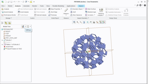
A circular plate of 50 mm diameter and 5 mm layer thickness is drawn by extrusion
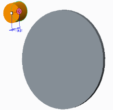
Then in the plate the required porous shape is created by negative extrusion
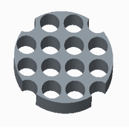
The same is placed over the 1st layer at an angle 30 degree.
Likewise total 5 are placed one above the other at an angle of 30 degree.
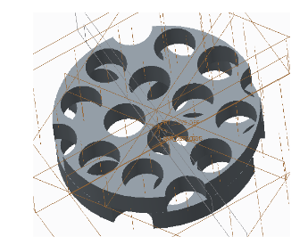
Exported it as IGES and then converted it to .stl
This .stl is opened in CURA and then exported as gcode format.
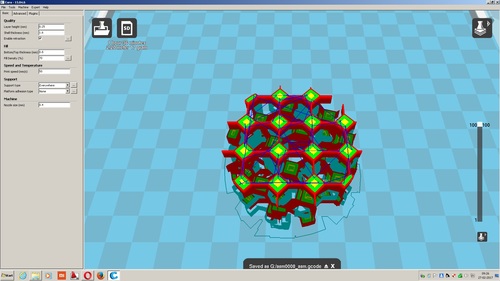
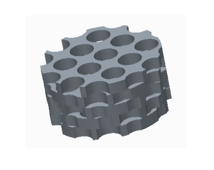
From the Menu- Print was selected.
After this the file was selected and after heating up the machine will start priting.
This is how it looked after printing.
3-D Desgin
3D scanner is a device that analises an object or environment to collect data on its shape and colour. The collected data can then be used to construct 3-D models. (wiki)
A 3D print/model is a digital representation of a physical object. This is done by processing the raw data gathered during a 3D scan into a digital model that can then be used for many purposes.
3D scanning
Kinect is a line of motion sensing input devices by Microsoft for Xbox 360 and Xbox One video game consoles and Windows PCs. Kinect uses an RGB camera with depth sensor and infrared projector with a monochrome CMOS sensor which sees the environment not as a flat image, but as dots arranged in a 3D environment. Like a game controller, the Kinect is an input device for the Xbox One. It can be used to identify who's playing the Xbox One, to sense the position of your body to control things on the screen, and to listen and react to voice commands. The device provides a natural user interface (NUI) that allows users to interact intuitively and without any intermediary device, such as a controller.
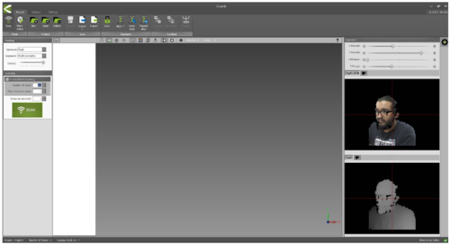
I used Kscan3D software for scanning process. In this a series of photos are taken while the object is rotated. The Software then combines all images to form a 3D shape. I selected no.of scans and selected the delay between image capture 4s. I sat infront of the Kinect, on a chair and rotated and took the images.
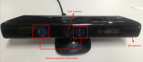
Vision camera - This video camera aids in facial recognition and other detection features by detecting three color components: red, green and blue. Microsoft calls this an "RGB camera" referring to the color components it detects.
Depth sensor - An infrared projector and a monochrome CMOS (complimentary metal-oxide semiconductor) sensor work together to "see" the room in 3-D regardless of the lighting conditions. Multi-array microphone - This is an array of four microphones that can isolate the voices of the players from the noise in the room.
Kscan3D
Kscan3D is a 3D scanner tool for kinect. KScan3D converts the data into a 3D mesh, it captures data from multiple angles to create a complete 360 degree mesh and align 3D meshes automatically. After completing the model can be exported in .fbx, .obj, .stl, .ply, and .asc formats.
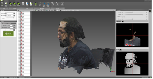
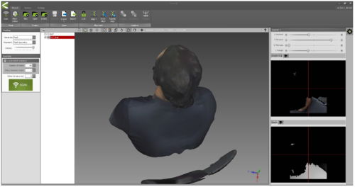
I sat on a rotating chair took 60 pictures in total for 360 degree complete chair rotation. Each had a gap of 3seconds. After taking the photos, all photos were aligned using align option. Click meshing tool, this tool will mesh all the pictures and will generate a smooth contour with exact color contrast 3D model. Once after checking the model, it can be exported to stl file for 3D printing.
The STL file can be downloaded here.