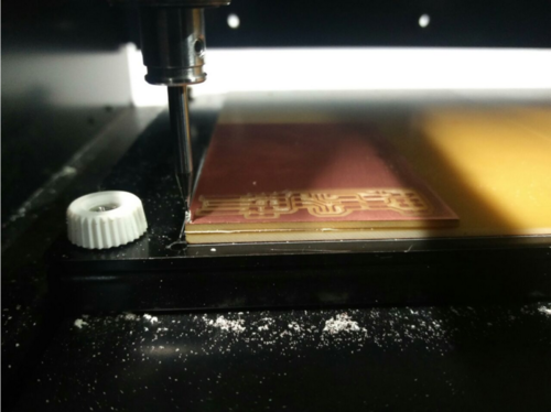
Milling the circuit
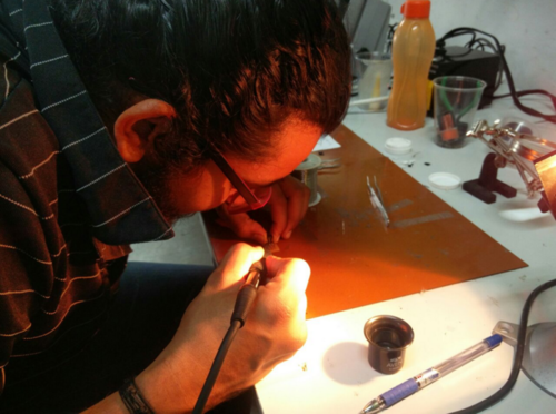
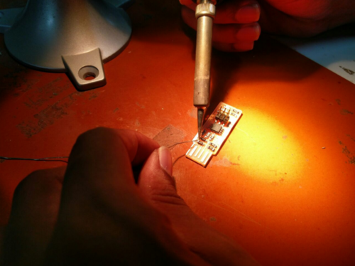
Soldering the components
Program the ISP programmerThis week's assignment is to build our own in-circuit FabISP programmer.
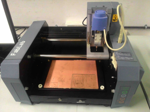
For that I learnt how to use Roland Modella MDX-20, soldering the components to the PCB and load the firmware to the chip.
FabISP is an entirely new term for me. The FabISP is an in-system programmer for AVR microcontrollers on the boards we make at FabLab. The FabISP itself can be made in Fablab using Modella and electronics workbench.
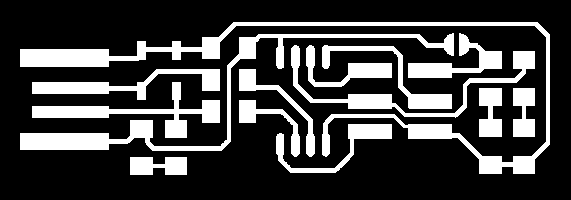
I selected Brian's board to mill.

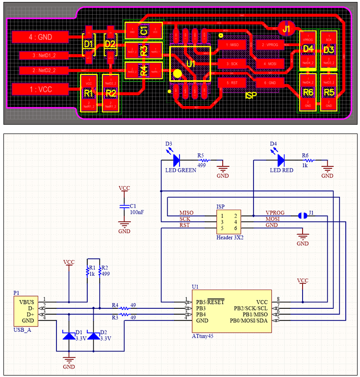
This is the schematic diagram used.
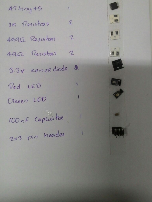
For creating FabISP, we need the following
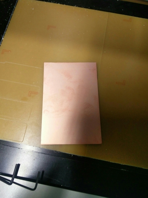
copper clad board
Double sided tape 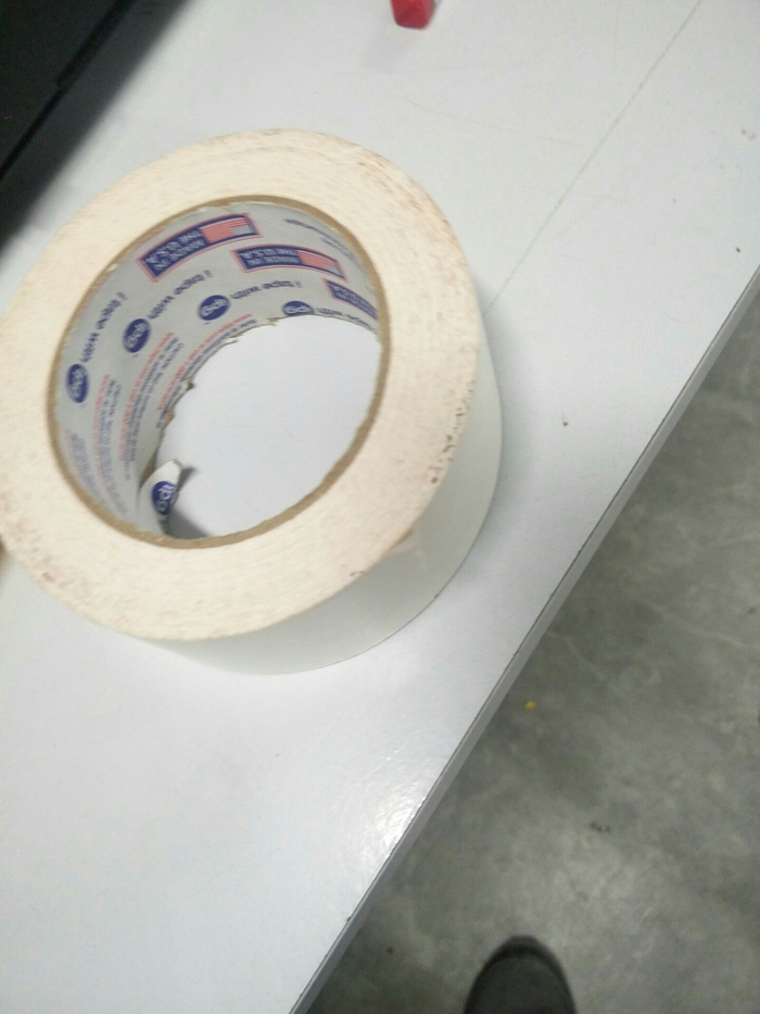
Mill Bits
Mainly there are two milling kits - here in our lab - (1/32 & 1/64). 1/100th is also there, but we're not using that.
Mill bits are classifieds based on their diameter, ends and flutes. For creating FabISP, mainly two drill bits are used here. 1/64 and 1/32
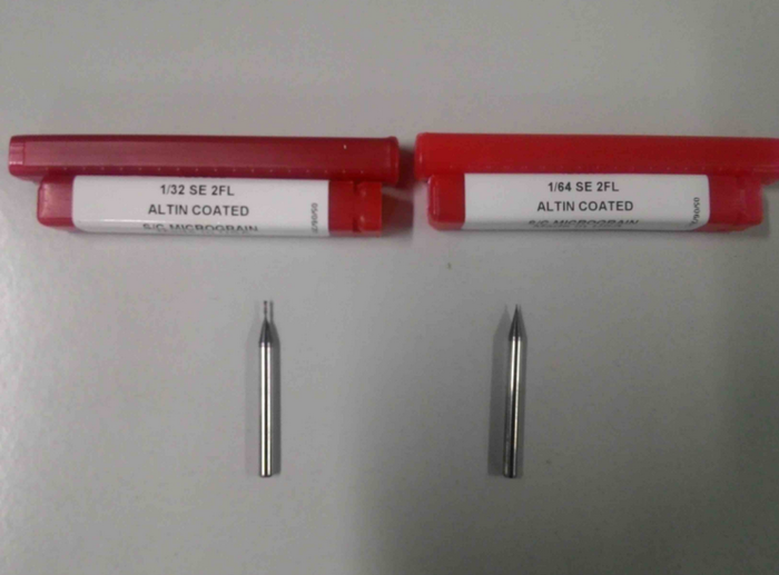
1/64 in drilling bit is used to remove copper layer from board 1/32 in drilling bit is used to cut the board.
First we fix the sacrificial layer on the platform of the machine.
Change the bed to metal bed.This is to make sure that the surface of the platform is not damaged, which is made of steel. Milling board is very sensitive to height, so place a sacrificial layer underneath. Metal board is used instead of acrylic sheet as the acrylic sheet has irregular shape. Copper plate is used as sacrificial layer upside down. Then we stick the double sided tape on the back of the copper clad board. Fix this board on the sacrificial layer and we'll be printing on this. We have to take proper care - so that air bubbles don't get trapped in between the layer. The air bubbles can result in the circuit board being unevenly placed due to which the circuit won't get milled properly. The Drill bit 1/64 inch is used to mill the traces and 1/32 inch is used to cut the board out.
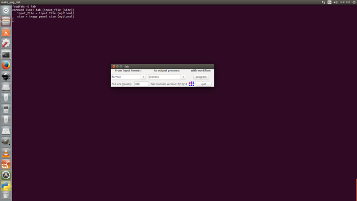
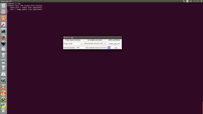
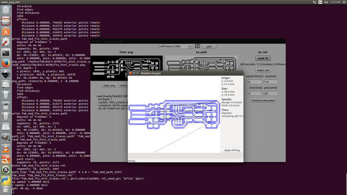
The bits, if fallen down on the bed / sacrificial layer can break easily.So we'll have to take extra care while removing the bit.We use fabmodules to run the machine. Just like vinyl-cutter last week,we select the input format and output machine.
1st we have to select the machine when the fab module appears.
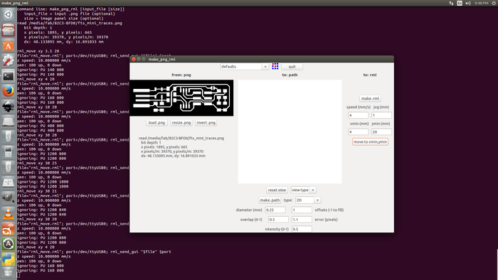
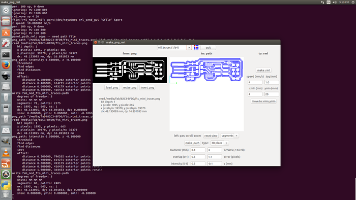
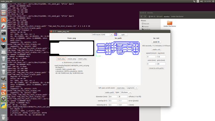
Make path
Change the x(min) and y(min) position according to the space where you need to mill the circuit in the board.
And then click on Move to xmin, ymin button.
Make .rml
Send it
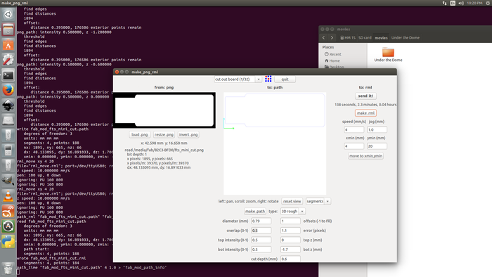
Once the circuit is printed on the board, for cutting, we have to change the mill. 1/64 is changed to 1/32! Now we have to change it in the fabmodule window as well.
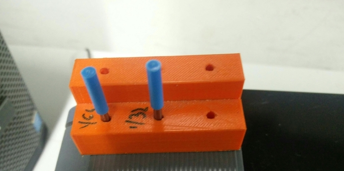
We are using smd(surface-mount device) for this. While gathering the smd's I wrote the components on a paper stuck a doublesided tape - in which I placed my components. This helped me in not loosing the components.
This was my first expirence in soldering. It turned out to be OK than a disaster I expected :P
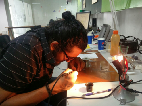
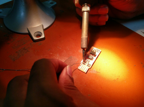
Finally I made it somehow :D
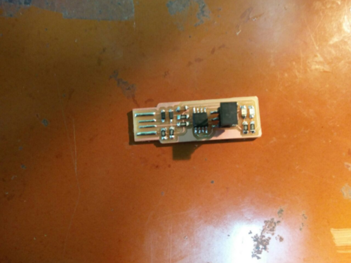
When connected to the PC the LED was glowing.
sudo pacman -S avrdude gcc-avr avr-libc make
I downloaded firmware from Brian's page and extracted it.Then I burned the firmware into the chip. For this another programmer was used. Our instructor had a programmer with him. This programmer is connected to the PC and the ISP is connected to programmer using ribbon cable.
Go to the firmware directory and check if Makefile contains 'PROGRAMMER' as 'usbtiny'.
Run make command to generate hex file. After this our directory will contain a file named fts_firmware.hex.
make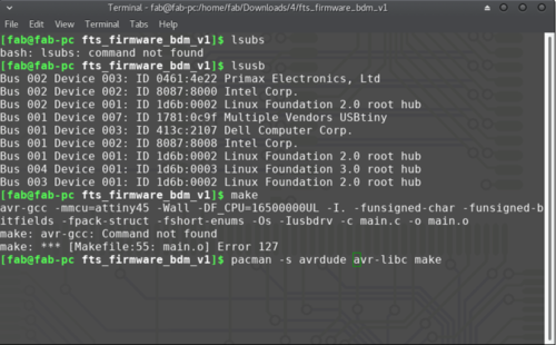
Run sudo make flash to flash hex file to the chip.
sudo make flash
Run sudo make fuses to setup the fuses.
sudo make fusesI connected my ISP to the computer and the LED was glowing. To check if the system is detecting usb, I gave
lsusb
This will list all the usb devices connected to the system.
Then I gave the dmesg command.
dmesg
This is to check whether there are any issues with the device. This command also prints the kernal messages.
Now my ISP is being detected by the system.It is working fine amd I am going to disable the reset pin to use that as an IO pin.
We disable reset pin so that we can use the pin for another purpose. And also not to be programmed again.
To disable the reset pin run the command
sudo make rstdisblTo check if my ISP can read other board, I used the below commands.
sudo avrdude -c usbtiny -b 9600 -p t45 -vThis is the video of testing my ISP!
This week I milled and soldered a PCB for the first time and it was fun.
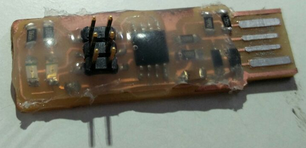
After soldering the instructor asked me to wash the PCB to remove the impurities.
Then he asked me to make the USB contacts flat using a file to avoid damaging of the USB port in the PC. The problem I faced was, the ISP was not a perfect fit. To make it a correct fit in the PC I used a small card-board. It fit perfectly afterwards.
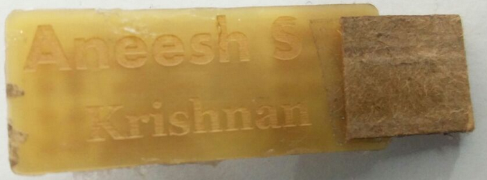
Using glue-gun I added an extra layer on top of the PCB. This I thought will give it a better look and protection! :-)
Then I etched my name on the back of the PCB. This was the idea of one of my friends here and we all thought it would be fun to do it. So using laser cutter we did that.