1. Introduction to Vinyl Cutter
2. How to use Vinyl Cutter
3. Introduction Laser Cutter
4. How to use Laser Cutter
Vinyl cutter is a very versatile device which can be used for a wide range of applications other than just sticker cutting such as making flexible circuits, making screen printing boards, make designs on fabrics etc.
This machine uses a sharp blade pressed against the cutting surface to make the necessary cuts. The blade can adjust itself in the cutting direction. In Linux systems we need to add the cutter as printer.
In our lab we have a Roland CAMM-1 GX-24 Servo vinyl cutter, few vinyl sheet rolls, screen printing boards etc
Any png image desinged in any designing software like GIMP, inkscape etc. can be fed to vinyl cutter through fab module. The input file should be a dual tone image in png format.
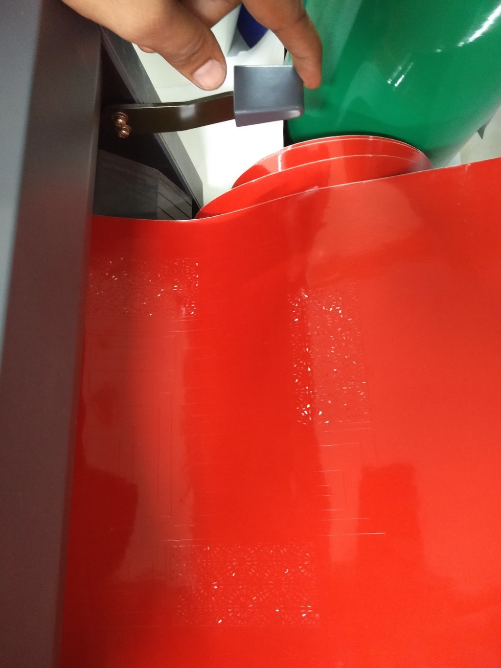
Loading the sheets
To load the sheet, I puled up the lever on the rear side of the vinyl cutter. This helps us load the vinyl rolls or peices of vinyl sheets.
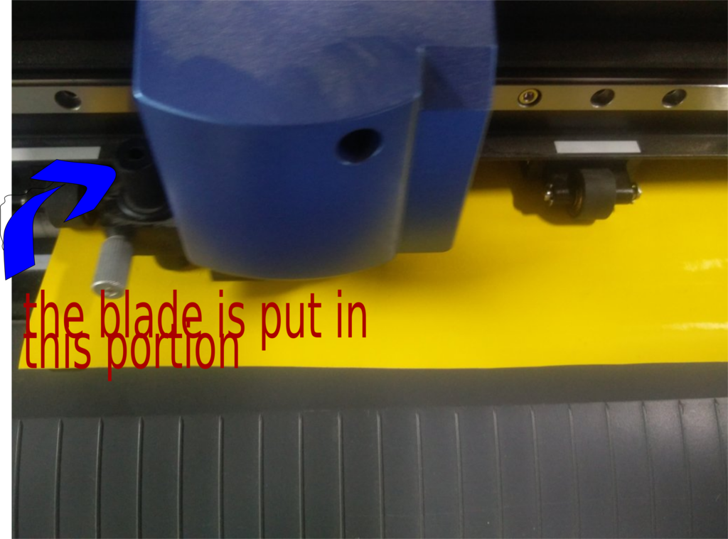
The blade is put in the machine as show in the figure.
The two rollers are positioned properly. We have to make sure that the rollers are positioned correctly on vinyl sheet and on the white markings on the machine.
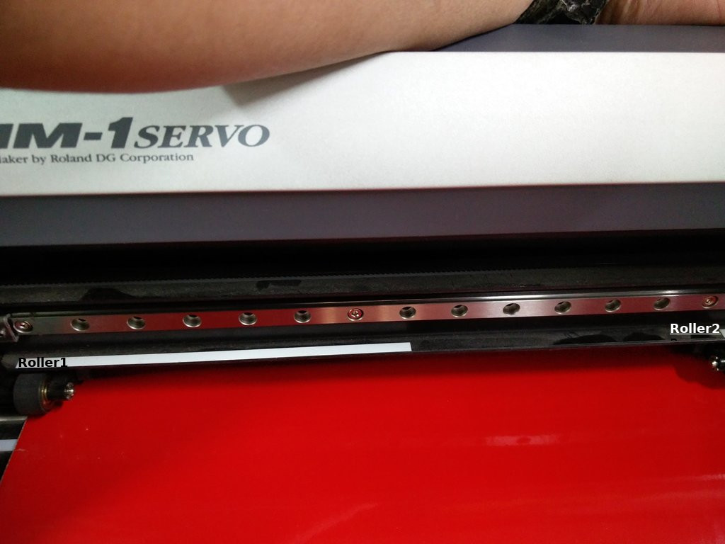
If the correct procedure is not followed, then the machine wont work. This happened for me the first time I tried using the machine. I didn't position the roller correctly.
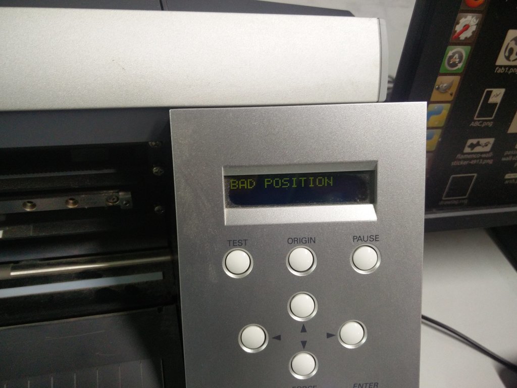
After this I figured out what is wrong and did it correctly.
We have two options - either to print on a sheet or to print on a roll. As shown below.
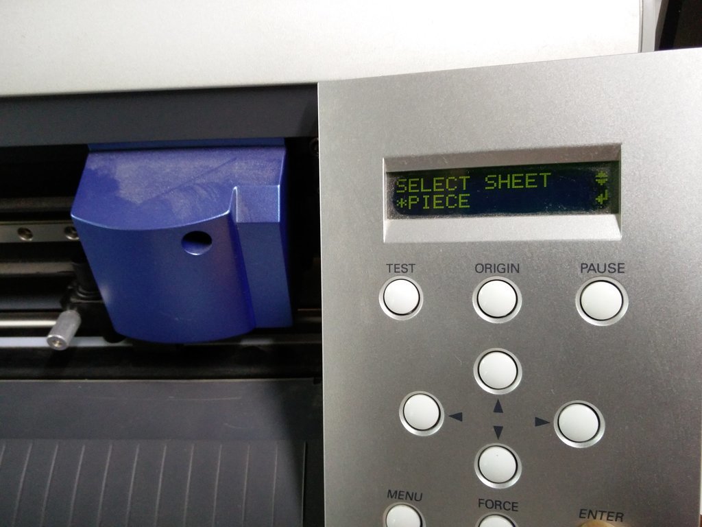
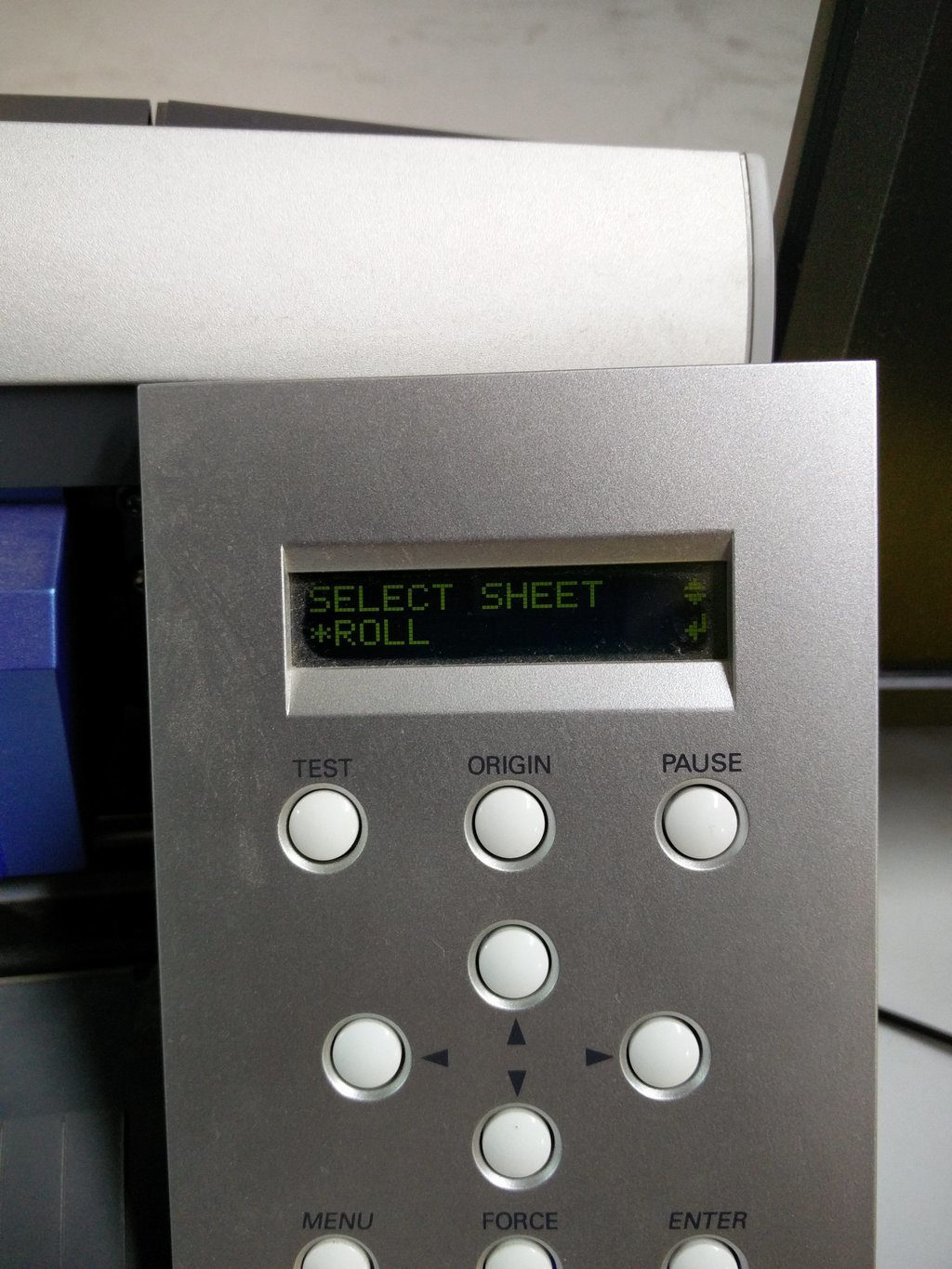
I used vinyl roll. The vinyl cutter will measure the lenght and width of the peice by rolling in and out. There are two sensors, one on the front and one on the rear side.
Once its done, orgin is set by moving the head with the arrow keys and after this is done we are all set to go.
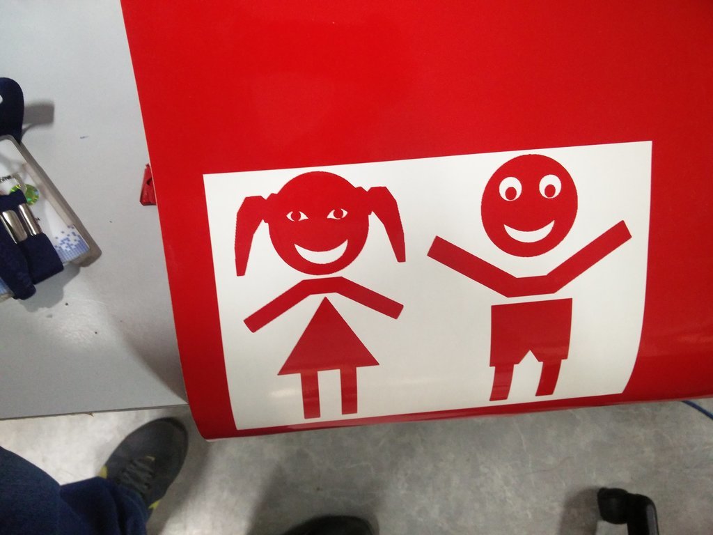
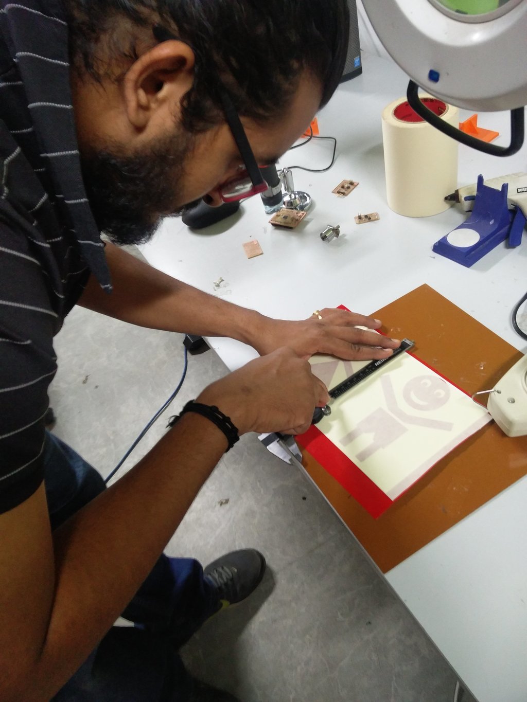
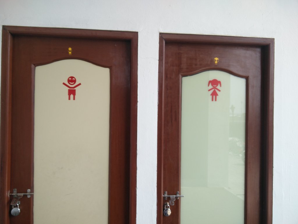
One of the assignments for this week was to create something with the Vinyl cutter. I used inkscape to design a simple sticker to stick on the toilet door in front of our fab lab. This may sound funny :P , but on a serious note, many people including people who come to the lab get confused and get into the wrong toilet as there is no sign on the door or wall. Hence I chose to stick something on the door so that the confusion will be avoided. Instead of using the cliche "MEN & WOMEN" symbol, I designed something very simple, funny and easy on inkscape.
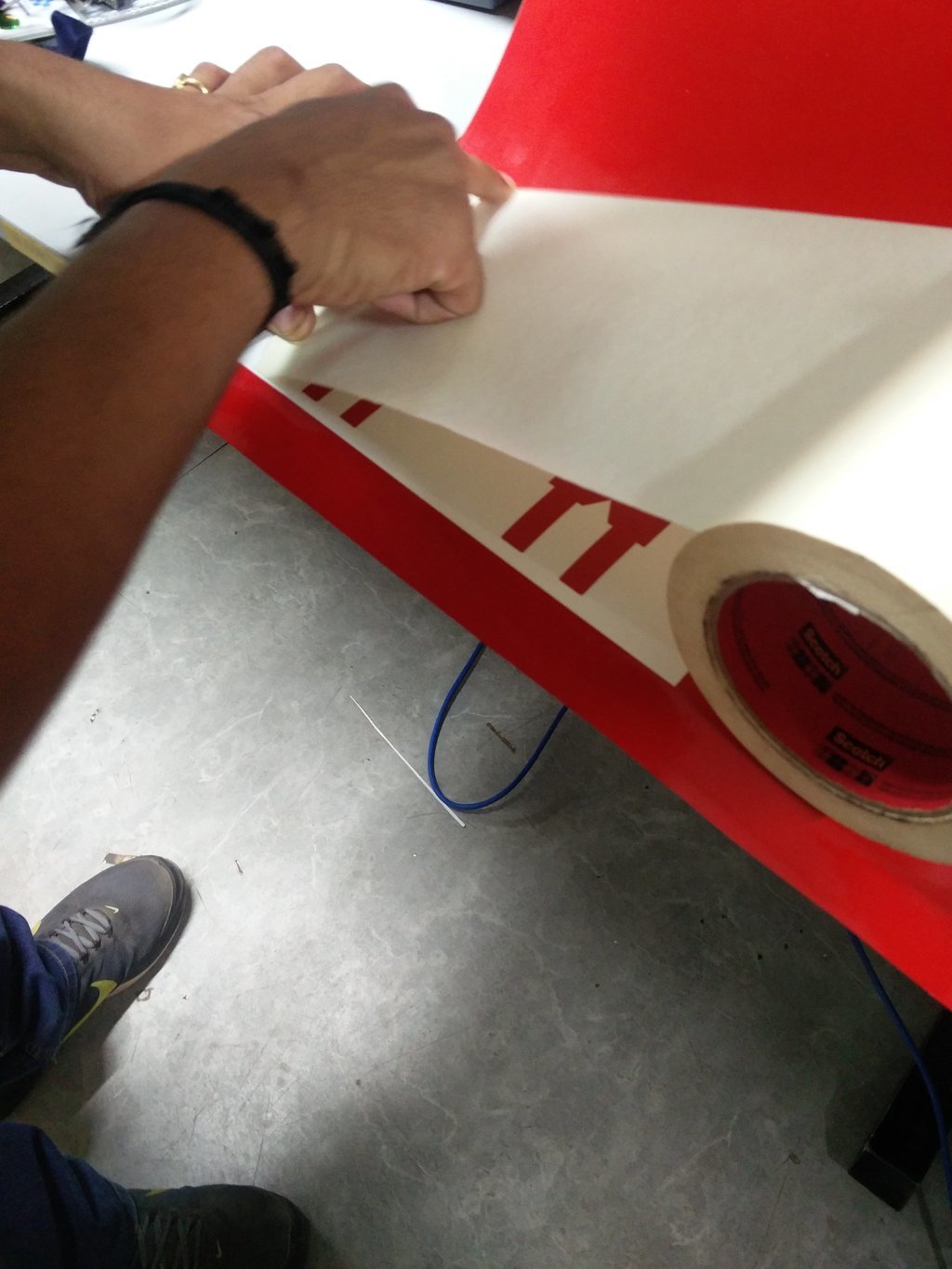
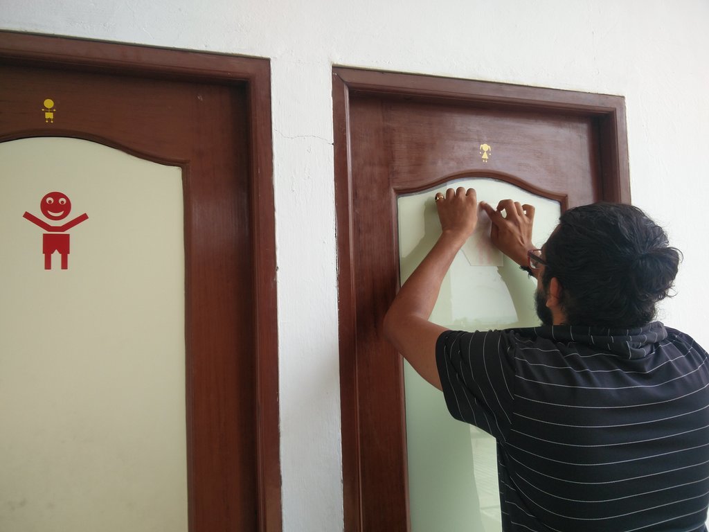
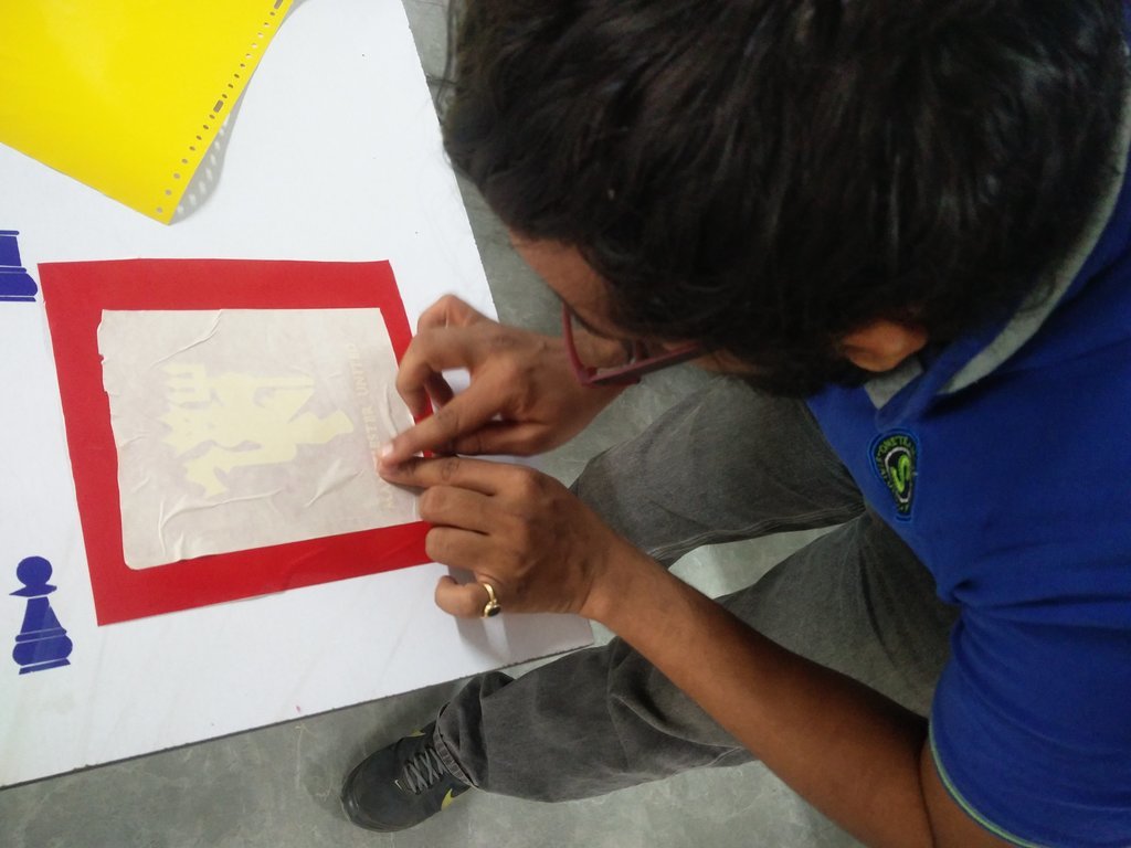
Once it is done,the sticker is to be transferred to wherever we need to stick it. It was done using masking tape. We use scotch tape here. Put the tape on the sticker and pull the tape. Now the sticker will be on the tape. Then just press it on any surface, and I used it on the door.
Original Files

1

2
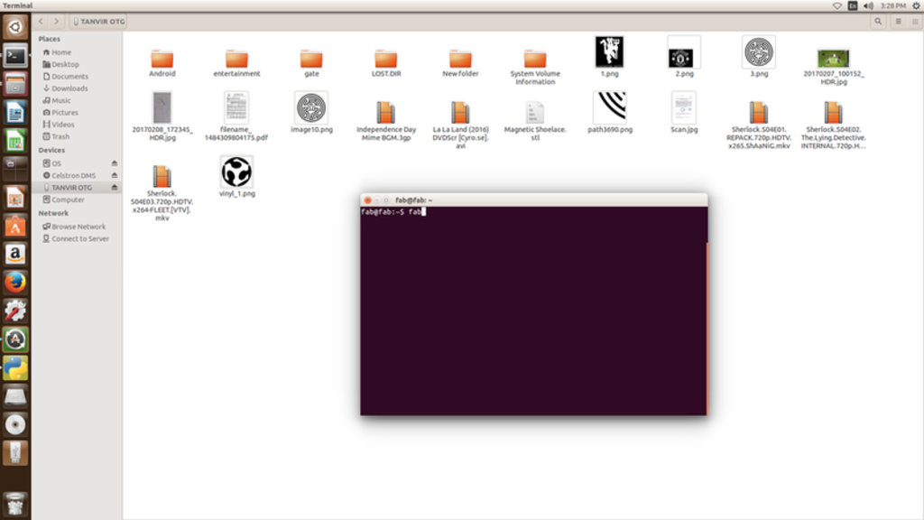
Once the design is complete and is loaded to the PC and the machine is set-up in the right way, we have to pass image to the machine. For this we use a command line utility.
Open a terminal and type 'fab'. This would open our software.
Choose input image format and output process options from select box and press 'make_png_camm' button.
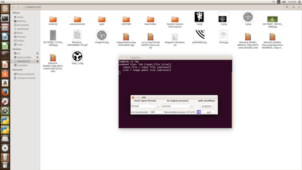
Choose input format and output (the machine is to be selected.)

Load the image by clicking on 'load.png' option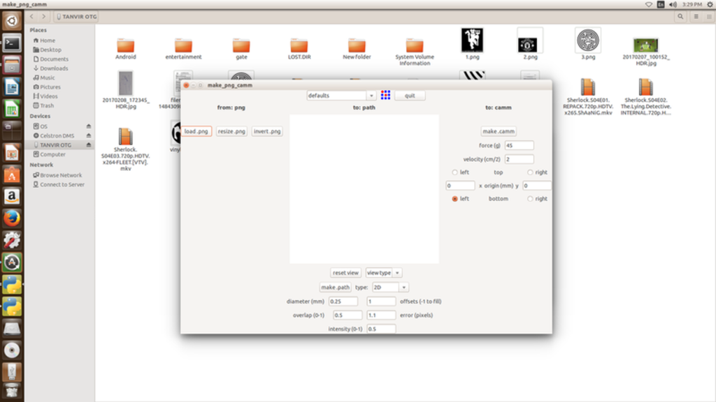
Load the image by clicking on 'load.png' option. Now choose necessary settings and then select 'make.camm' option and then send the image.
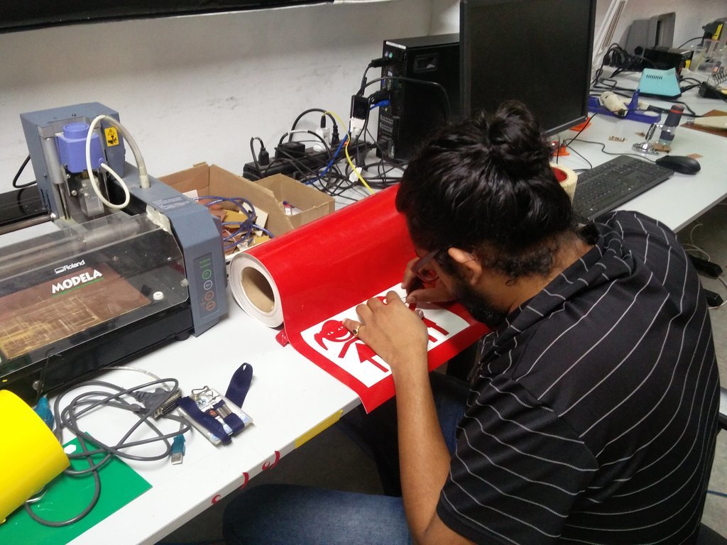
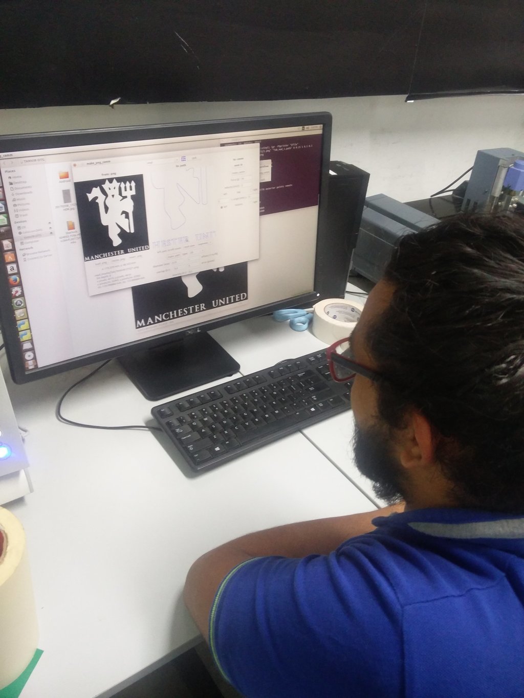
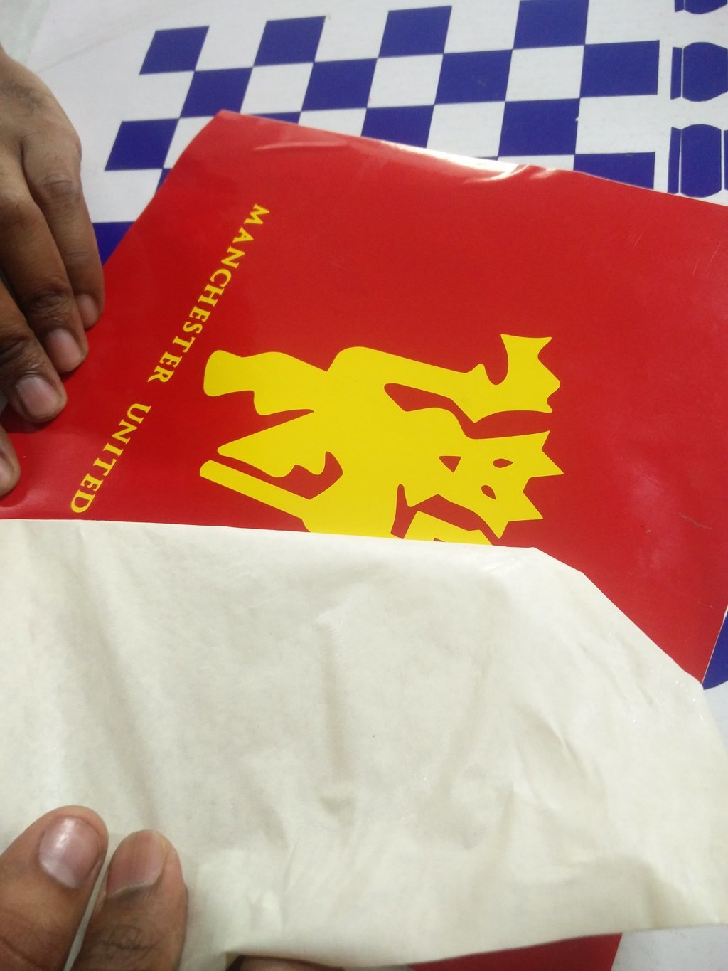
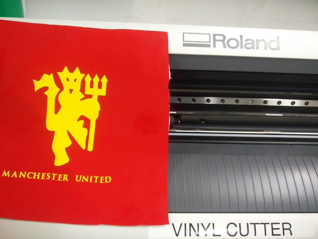
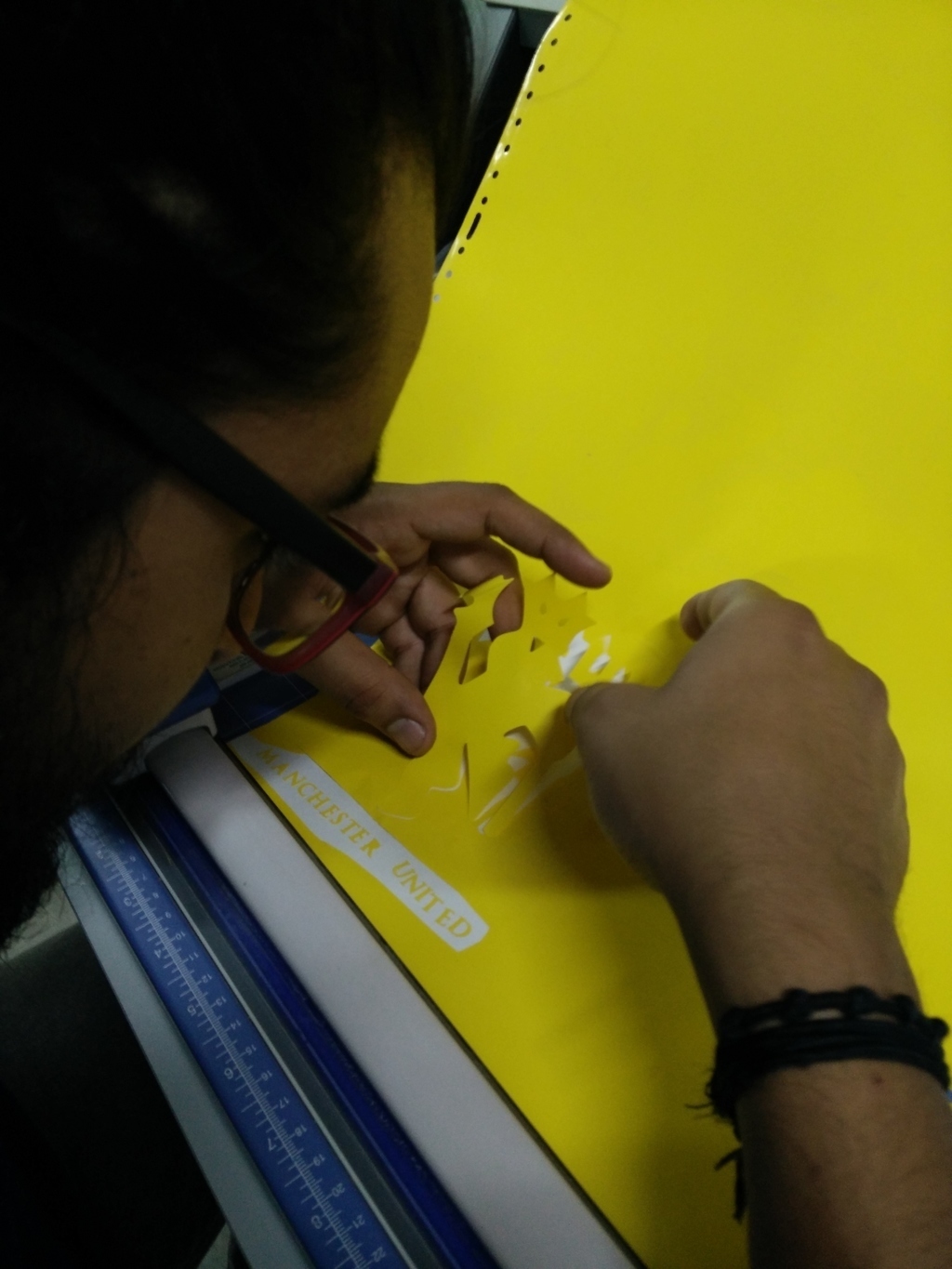
I also tried making another sticker. I didn't design it, but downloaded the logo from the internet and traced it in inkscape and made it in Vinyl cutter. For this I used two sheets. Yellow and Red. The logo was initially designed in yellow,and then I used Red for its background. The downloaded file was edited in inkscape using bezier curves, node editing tool etc. Once the image outline is set, select the images and do these operations = OBJECT>CLICK>SET. This option will crop the necessary image. Then select 'trace bitmap' ( Shift + Alt + B ) to trace bitmap and fill color. It was then exported as png for further operations.
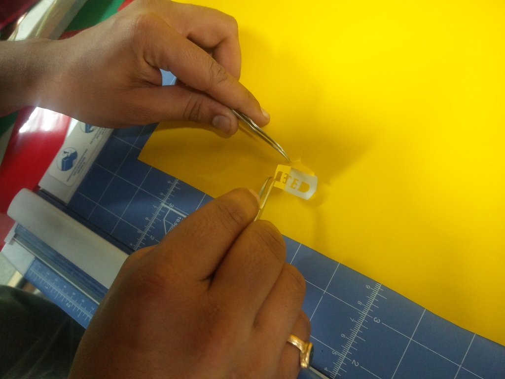
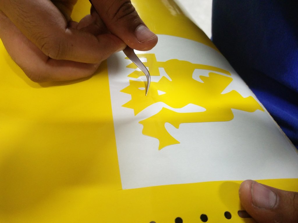
I used forceps and knife to cut the tiny parts of the sticker, like alphabets, eye of the devil/the design etc.
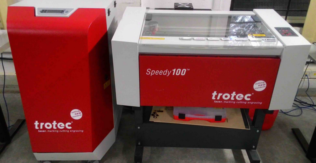
The machine we have in our lab is Trotec Speedy 100 which houses a CO2 laser which have enough power to cut through wood some plastics, cardboard, acrylic etc. It cannot cut metals but can engrave on its surface. Fabrics can also be cut using this machine. Our laser cutter bed size is 2 feet by 1 foot which can be approximated as 600mm X 300mm.
Trotech Trotec Speedy 100 is a entry level CO2 laser cutter. It got 60W power max for its cutting/engraving operation. The general idea of CO2 laser system is that a beam is directed down to a part for cutting/engraving. The part sits on a stationary platform and the laser beam move around the piece. Cutting is acheived by passing the beam through a focusing lens (Zinc Selenide lens). A focused beam exits through the bottom of a cutting head nozzle. Gas/air is fed into the side of the chamber below the focusing lens by means of a fan. This gas exits the nozzle along with the beam and the laser beam combination serves to vaporize the material for cutting.
This is the machine.
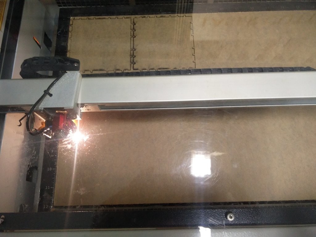
The cutting by the laser is shown here. In this figure, the laser is cutting through 3mm acrylic board.
The head of the laser needs to be focused depending on the kind and thickness of the material used. Focussing is made possible with the focus tool shown in the picture below. This tool is hanged on the head and the bed is moved closer to the head using arrow keys on laser cutter till the focus tool touches the material in the bed and falls down.
This is the focus tool.
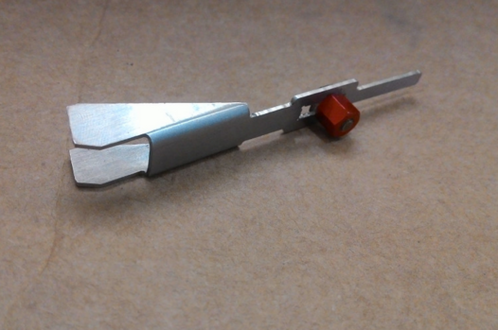
As the focus tool falls down, the optimal focus position for that material in bed is obtained. Once the focus is set, we can cut or engrave.
The machine cuts/engraves a material depending on the speed to power ratio.
For Cutting     - high power and slow speed
For Engraving   - low power and high speed.
Another assignment we have this week is to design and laser cut a Parametric press-fit kit using laser cutter.
The dimension of the material can be easily measured with a vernier scale. But to know the tight fit and loose fit dimensions of a material, a comb-like structure is designed to check the kerf.
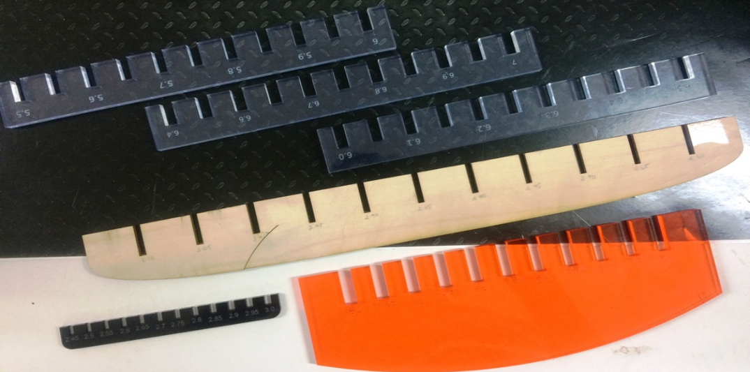
Here, in Kochi, we have acrylic of thickness 3mm 5mm & 6mm, cardboard and plywood.
There are 5 awesome people here and we decided to take one each. I chose acrylic of thickness 3mm and made a comb structure.
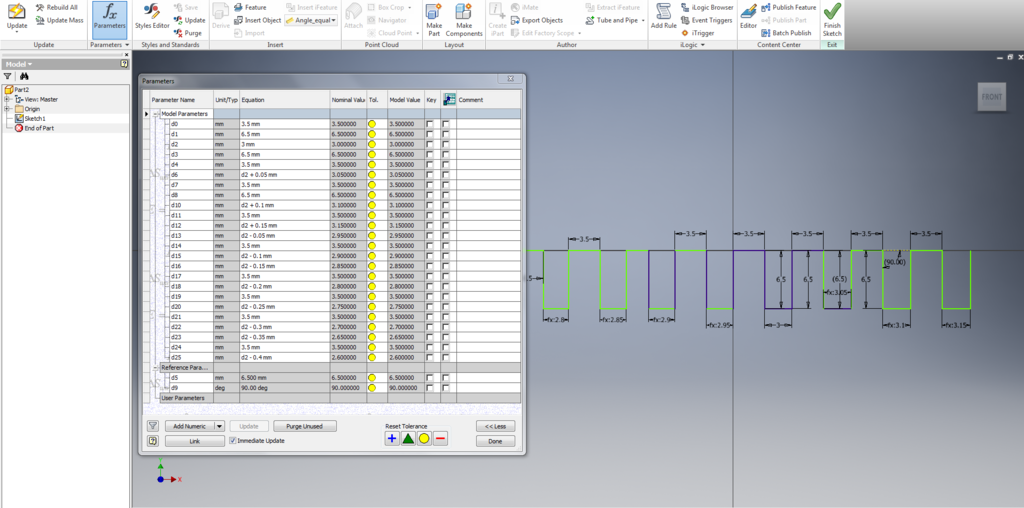
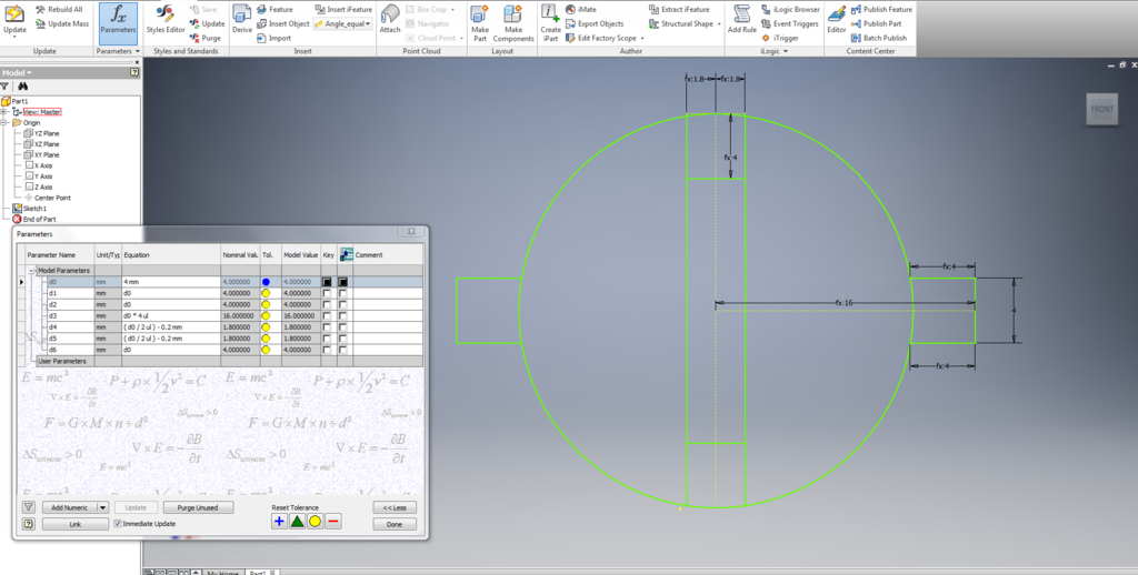
I used Inventor for doing parametric design of comb with slits of various width. For my part of the assignment, I had worked on acrylic - 3mm. I developed a parametric comb in inventor , giving an increment and decrement of .05mm. Now, I exported the file as a dxf file and opened on inkscape to give a print to the laser cutter. The parametricconstruction screenshot is shown below.
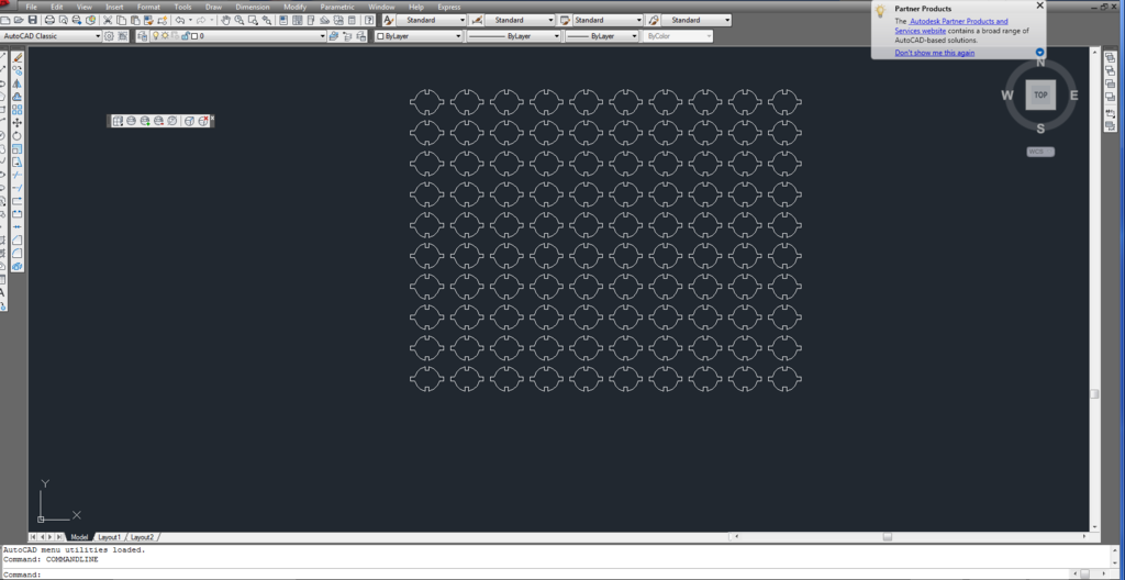
I also exported the .ipt file as .dxf so that I can import the file in autocad. This is basically for fine-tuning! In the 2nd week, I tried both inventor and autocad. Also, it is easy to import .dxf file in inkscape & coreldraw.
Here is the autocad file :
Design was then exported dxf file for processing in Laser Cut Machine.
The image was then edited using inkscape.
I added the measurements as well, so that it can be engraved.
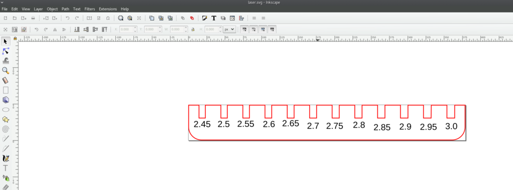
Then the outline color changed to red. Machine is set in such a way that Red part is cut by the laser and the black is engraved. This is preset setting which can be changed if necessary.
inkscape file : 
Once the focus and origin is set in the machine, we can give the print command.
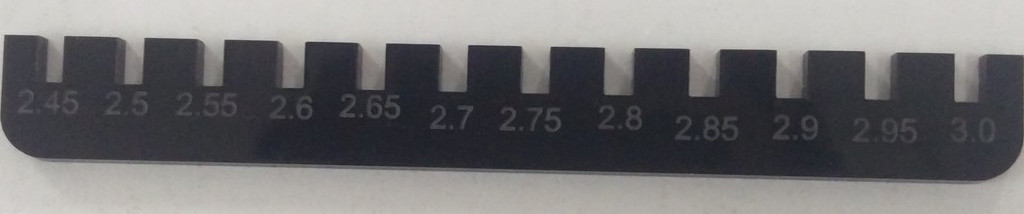
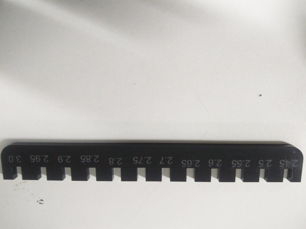
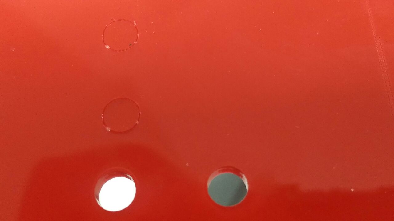
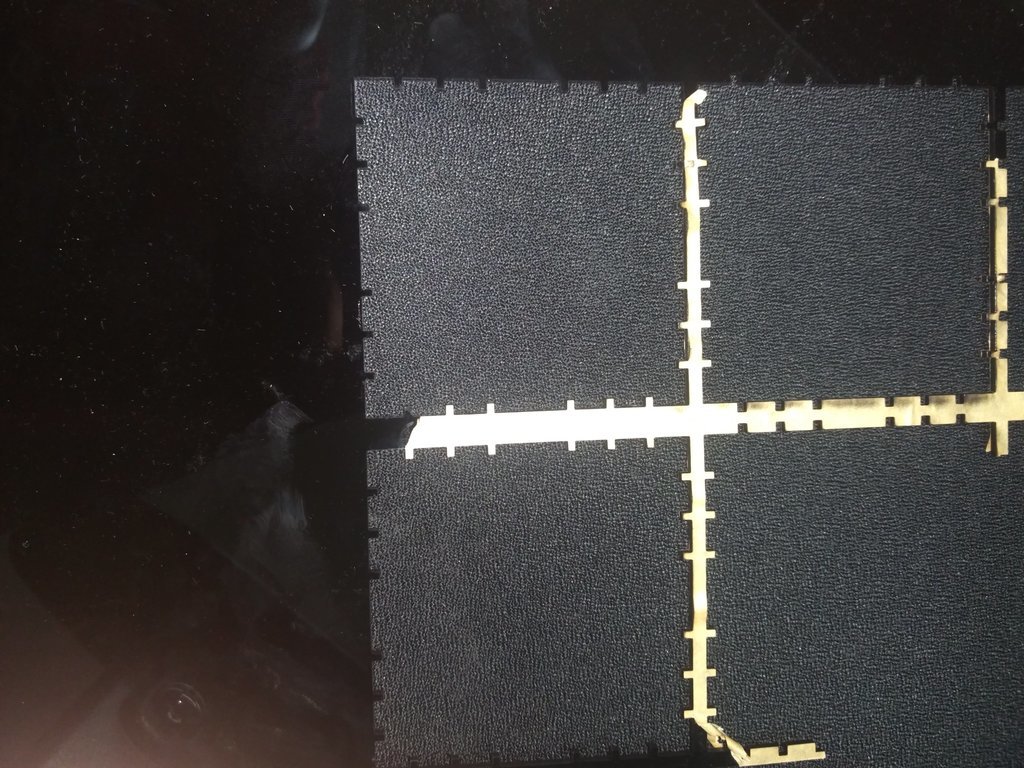
For 3mm acrylic sheet I cut a comb as shown. But across the sheet the tight-fit parameters were way too different. At one end it was 2.65 at another it came up to 3. Therefore I did my press fit construction kit in cardboard.
1
Initially, I gave POWER:75 ; VELOCITY: 5; PULSE:50000; Number of passes:2
This is the first cut in the below figure. The circle didn't come off.
Then I changed it to POWER:100 ; VELOCITY: 5; PULSE:60000; Number of passes:2
As shown in the figure, the second circle didn't come out as well.
Then I changed the parameter to POWER:100 ; VELOCITY: 0.5; PULSE:60000; Number of passes:2
This gave me a proper cut. This is the 3rd circle.
But I wanted to try once more.
I changed the parameter to POWER:100 ; VELOCITY: 1; PULSE:50000; Number of passes:1
This gave me a proper cut.
So I used this parameters for cutting the acrylic.
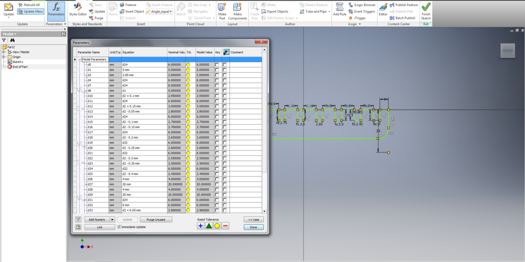
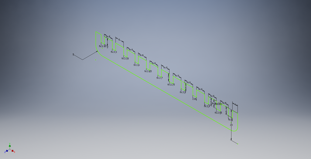
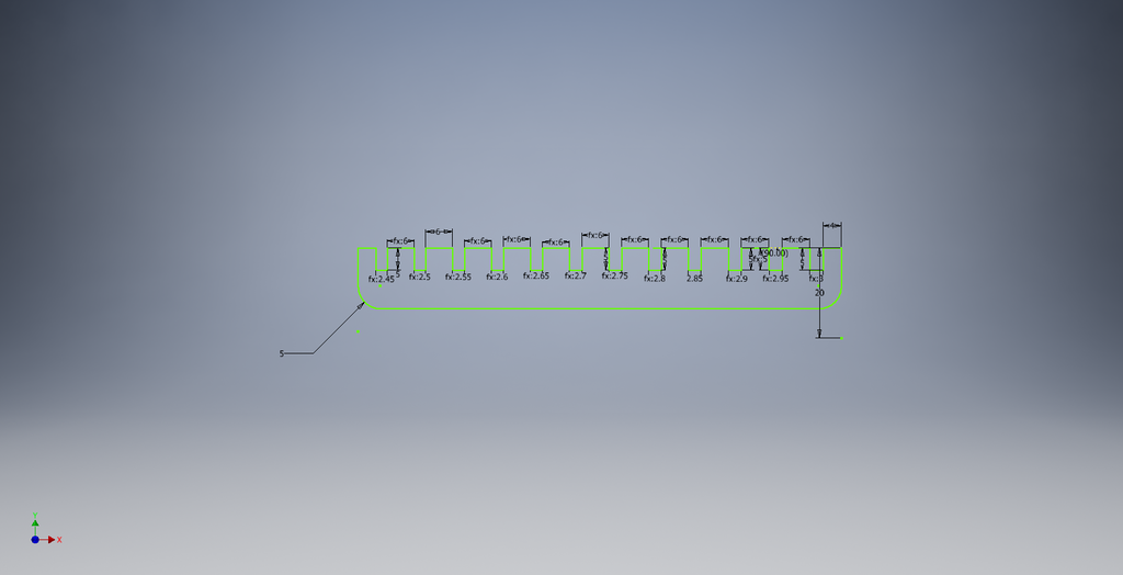
I used Inventor for doing parametric design of comb with slits of various width as shown in the screenshot below. d0 s the base dimension. When we change the base dimension, other parameters such as d1,d2,d3 etc changes accordingly. For example : The relation between d0 & d1 is d0=d1 The other relations are as shown in the figure.
I also exported the .ipt file as .dxf so that I can import the file in autocad. This is basically for fine-tuning! In the 2nd week, I tried both inventor and autocad. Also, it is easy to import .dxf file in inkscape & coreldraw.
Screenshots of the work.
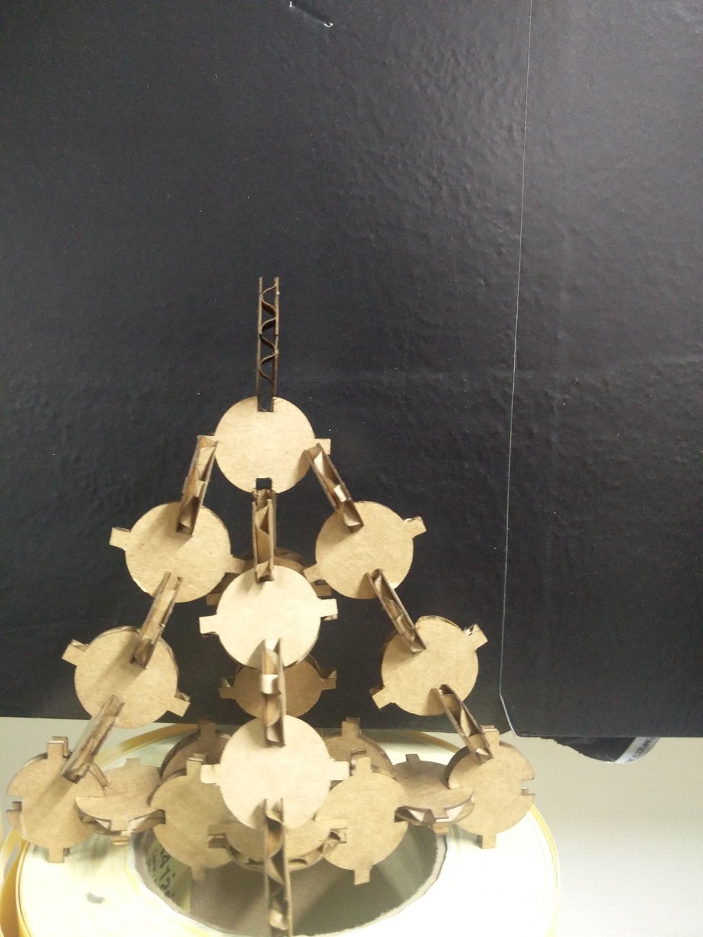
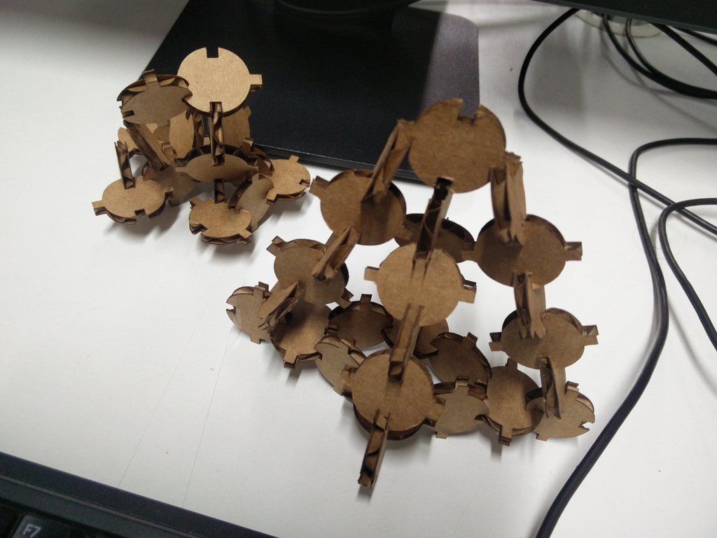
After cutting the cardboard I arranged the pieces to make different models.
Some of the random models I made are :
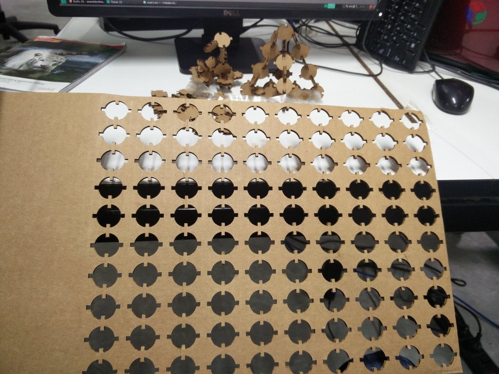
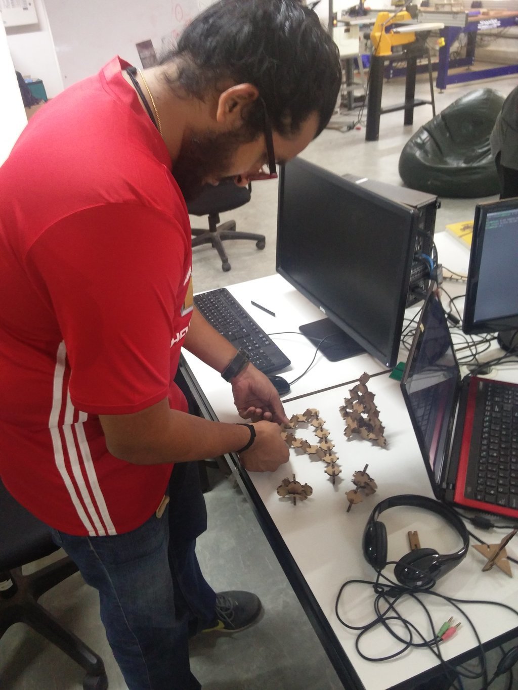
Some of the random models I made :-D
I wanted to make something like a DNA structure but it turned out to be something entirely different :-{ :P
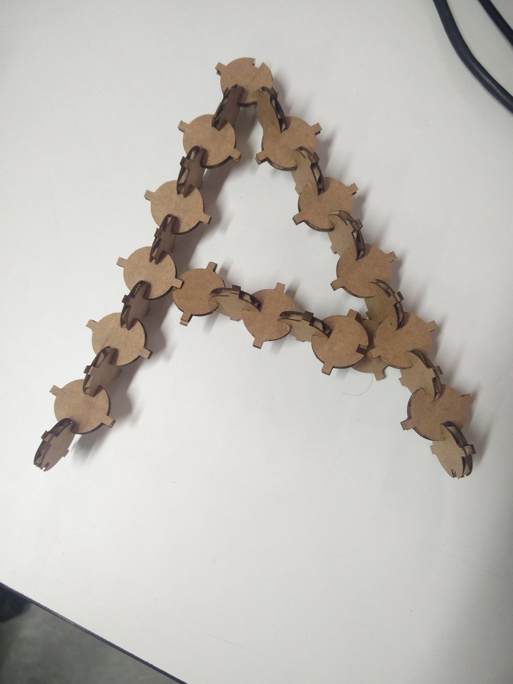
Letter A ;-) 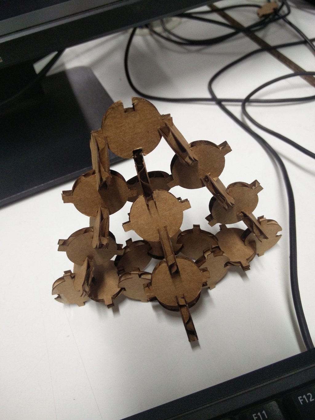
Vinyl - I was over-excited this week as the main thing I was looking forward to started this week - Learning how to use the machines. And as it was one of my all time favourite logos I got carried away! Instead of removing the out line, I scrapped out the portion which was to be taken in the masking tape.
:-P <embarrassed> :-D
Laser - I was trying to make a parameteric press fit box and I forgot to add the error factor / kerf.
Acrylic board from which I cut the
I used Inventor for doing parametric design of the box.
Inventor Files
I also exported the .ipt file as .dxf so that I can import the file in autocad. This is basically for fine-tuning! In the 2nd week, I tried both inventor and autocad. Also, it is easy to import .dxf file in inkscape & coreldraw.
Here are the autocad files :