Week 16 - NETWORKING & COMMUNICATIONS

Assignment

. Design and build a wired &/or wireless network connecting at least two processors.

This week we have to design and build a wired or wireless network connecting at least two nodes. It is similar to speaking. We will learn how to talk with other devices like computers, controllers etc. I'm planning to make a small network based on serial asynchronous bus. The asynchronous serial interface is so called because the transmitted & received data are not synchronised over any extended period of time and hence no special means of synchronising the clocks at the transmitter and receiver is necessary.
softwareSerial
Serial communication in an arduino board which has dedicated UART/USART port. And, if I'm using arduino IDE then serialSoftware library is very essential. Simply saying it helps to have any i/o port to be Tx/Rx pins. another reference is as always Prof. Niel's examples. After giving it a lot of thought I decided to make a master board and 2 slave boards.

Designing of the board

I used EAGLE to design the board. First I made the Master board and then two Node boards. The bridge and the 1st node had attiny 45-10su and the 2nd node had attiny 44a. The schematics and Board designs are in the images below.

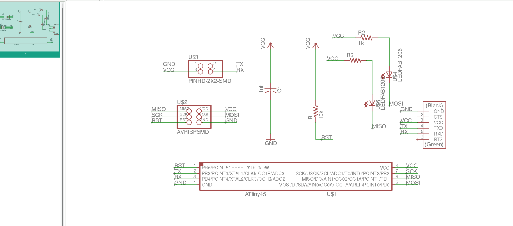
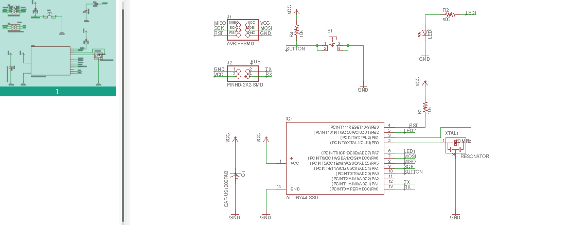
1. Schematic of Bridge board.


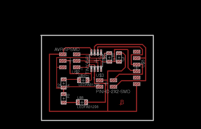
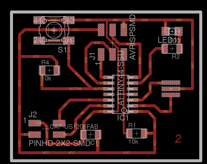
2. Design of Bridge board.


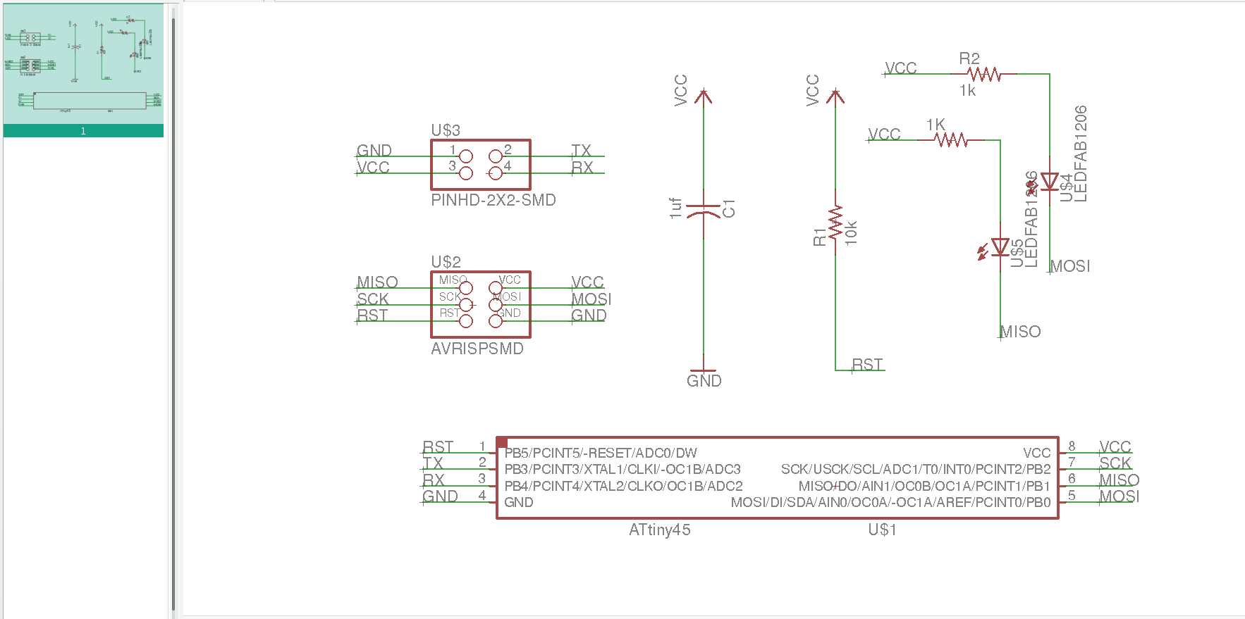
3. Schematic of 1st Node board


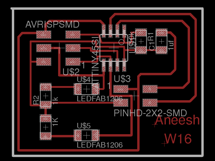
4. Design of 1st Node board


5. Schematic of 2nd Node board


6. Design of 1st Node board


Making of the boards


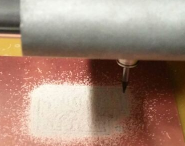
I milled the boards in modella and stuffed it.


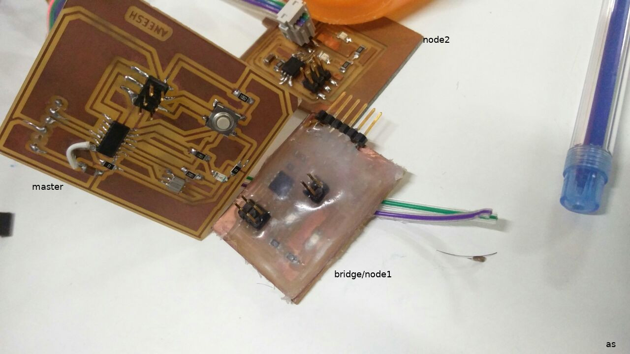
I glued the bridge board after soldering. For the node boards I used some of the small - left-over - boards lying here in the lab. So I didn't seperatly make a cut path for the node boards.! This saved me a lot of time as well :)

Programming of the boards

Master Board :


  #include 
  SoftwareSerial mySerial(0,1);

  const int buttonPin = 8;
  const int ledPin = 7 ;
  int buttonState = 0;
  int i=0;
  int nodes = 2;

  void setup() {
    mySerial.begin(9600);
    // initialize the pushbutton pin as an input:
    pinMode(buttonPin, INPUT);
    pinMode(ledPin, OUTPUT);
    digitalWrite(buttonPin,HIGH);
  }


  void loop() {

    buttonState = digitalRead(buttonPin);

      if (buttonState == LOW) {
     mySerial.print("node id = ");
      mySerial.println(i);
     mySerial.write(i);
      digitalWrite(ledPin, HIGH);
      i++;
      delay(200);
      if(i > nodes)
       i = 0;
      }
      else {
   digitalWrite(ledPin, LOW);
    }


  }


Slave Boards


  #define nodeId '1'
  #include 
  SoftwareSerial mySerial(3,4);

  const int ledPin = 0 ;      // the number of the LED pin


  char data;

  void setup() {
    // initialize
    pinMode(ledPin, OUTPUT);
    mySerial.begin(9600);
  }

  void loop() {
  data = mySerial.read();
  mySerial.println(data);
    if (data == nodeId) {
      digitalWrite(ledPin, HIGH);
      }
      else {
      digitalWrite(ledPin, LOW);
      }
  delay(10);
  }


For the second slave we just have to change the node ID. When the node ID becomes = 1 the LED in the first board should blink. and when the second slave is selected , ie, when i=2 the LED in the second board should blink.

Issues Faced.

After writing the program and flashing it to the board I connected the boards as shown in the video below. When the switch is pressed, the LED in the master blinks, but the LED in the slaves is not blinking. Have to debug now.
Initially the master board was not working. Then I found out a small error in the code and changed it.

Then after connecting all the 3 boards together including the serial port I tried.


Design Files

The schematic, board design and png files of Bridge Board can be found here.
The schematic, board design and png files of 1st Node Board can be found here.
The schematic, board design and png files of 2nd Node Board can be found here.
The program burned to the master and slave boards can be found here. here.