. Measure something: add a sensor to a microcontroller board that you have designed and read it.
Hall Effect Sensor
This week I'm planning to use a Hall-Effect sensor as my input device.
Hall Effect Hall Effect Sensors are devices which are activated by an external magnetic field. We know that a magnetic field has two important characteristics flux density, (B) and polarity (North and South Poles). The output signal from a Hall effect sensor is the function of magnetic field density around the device.
I'm planning to make a board such that the LED lights up when a magnet is brought near to the hall-sensor.
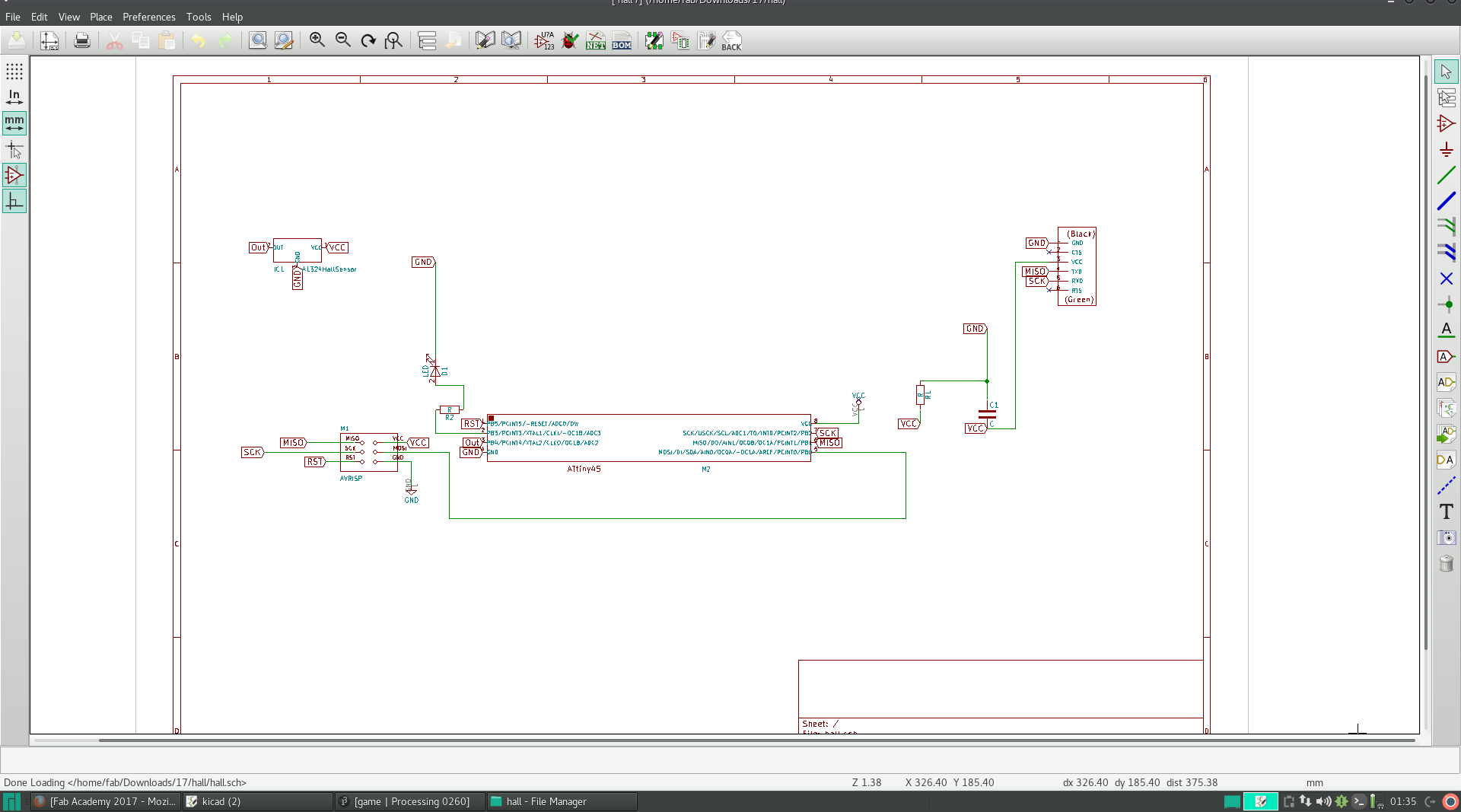
For designing this board I reffered Niel's Magnetic effect-Hall sensor board.
I added an LED on PB3 of ATTINY45 IC.
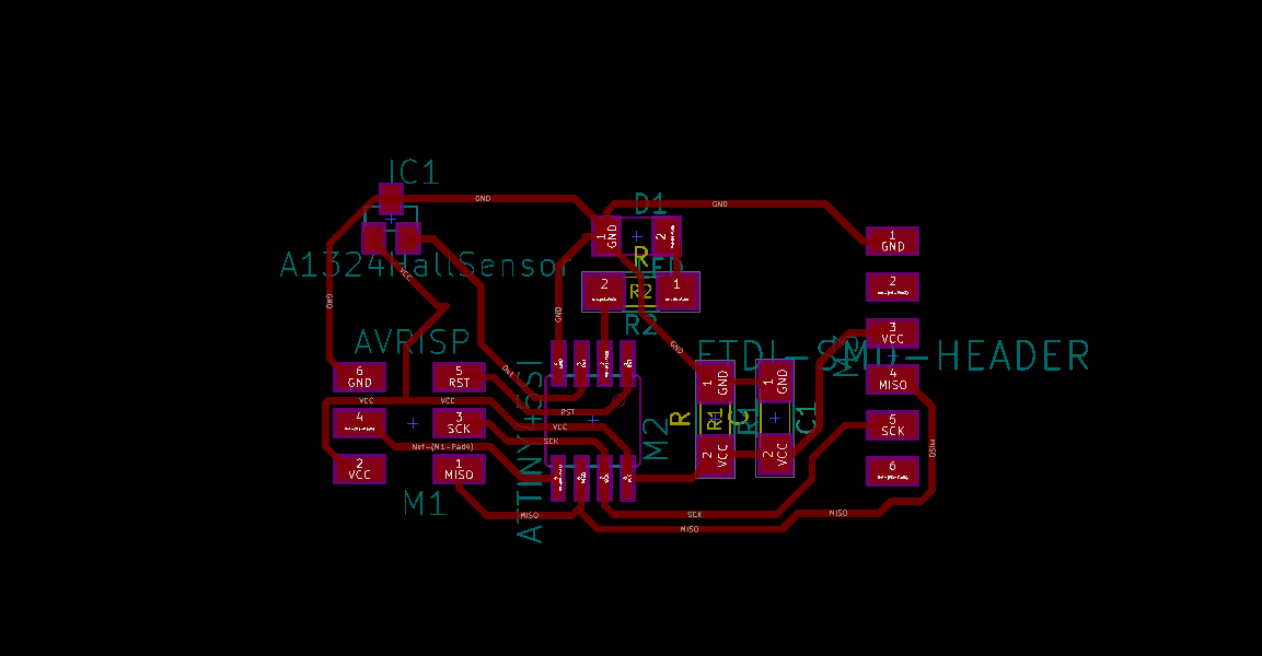
I'm using KiCAD to make the schematic and the board diagrams.
While adding the components I realised that Hall sensor / A 1324 sensor was not there.
So I selected something that looked similar to the sensor - that was Regulator SOT23.
I compared the data sheet of this Regulator and Hall effect sensor and interestingly I found that even though three pins are there, the orientation of the pins are the exact opposites.
I then decided to use OUT as IN and IN as OUT of the regulator.
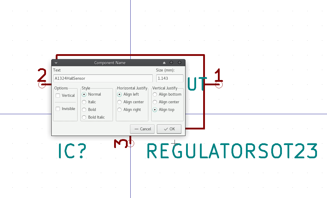
But my instructor Sibu said I can make a new component according to my wish in these softwares.
So I edited the Regulator.
This is an easy operation.
Edit component -> Edit with Library editor.
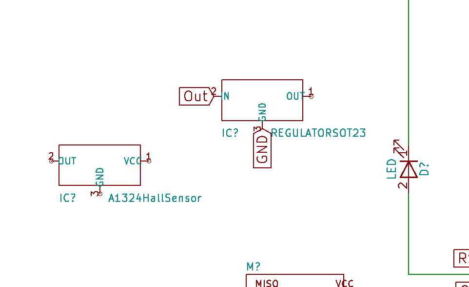
I changed the name and the inverted the 2 ports.
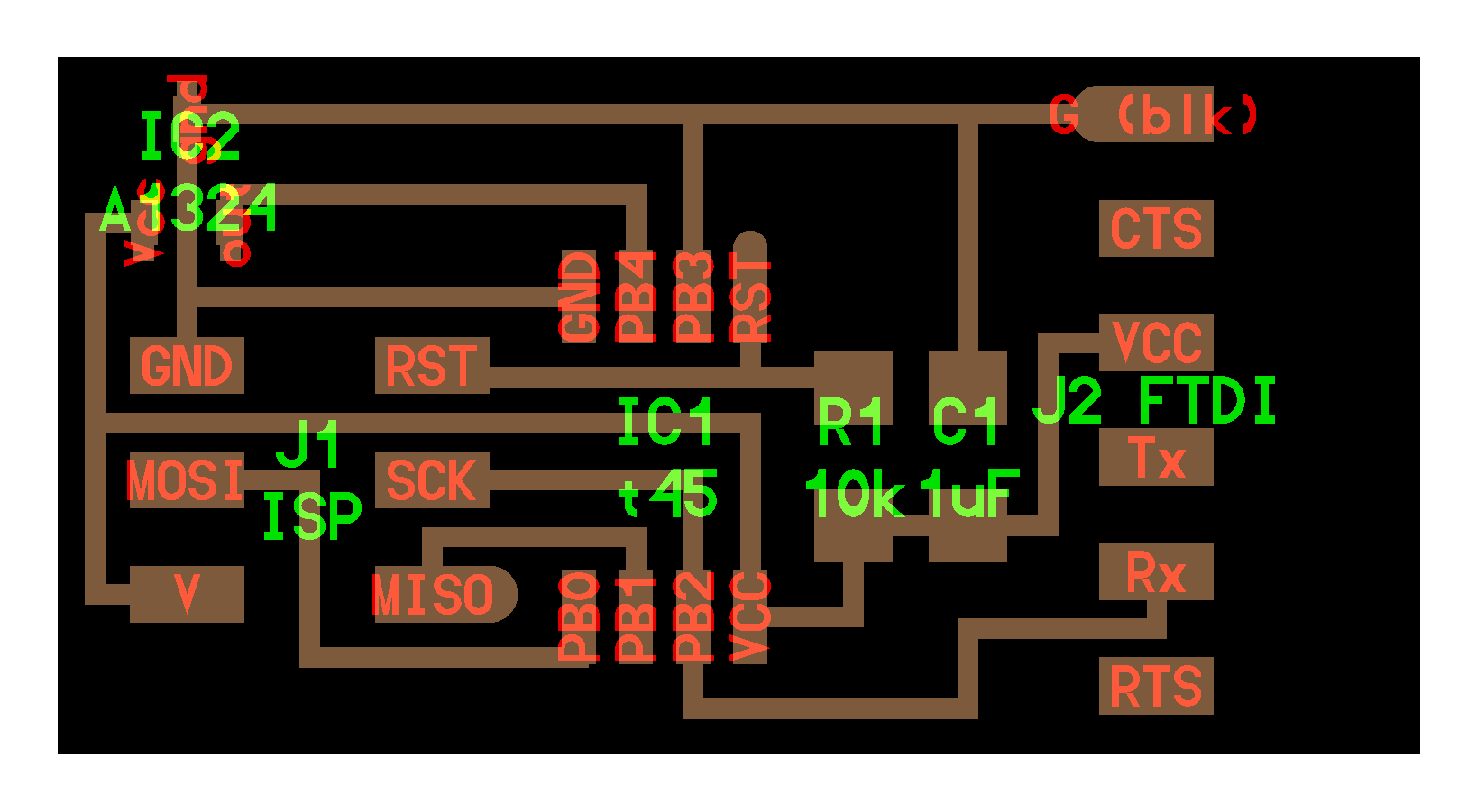
After the Hall Sensor was created, I completed the pinout as shown below.
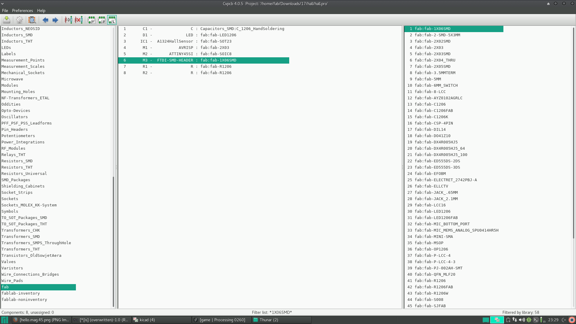
After making the circuit I added the footprints. In place of the Hall sensor I added SOT23 regulator from fab library as shown below.
Then I made the board by keeping Niel's board as reference.
After making the board design I exported the svg file,opened it in inkscape and exported the black and white trace image and the board-cut image in the png format for milling and cutting respectively.
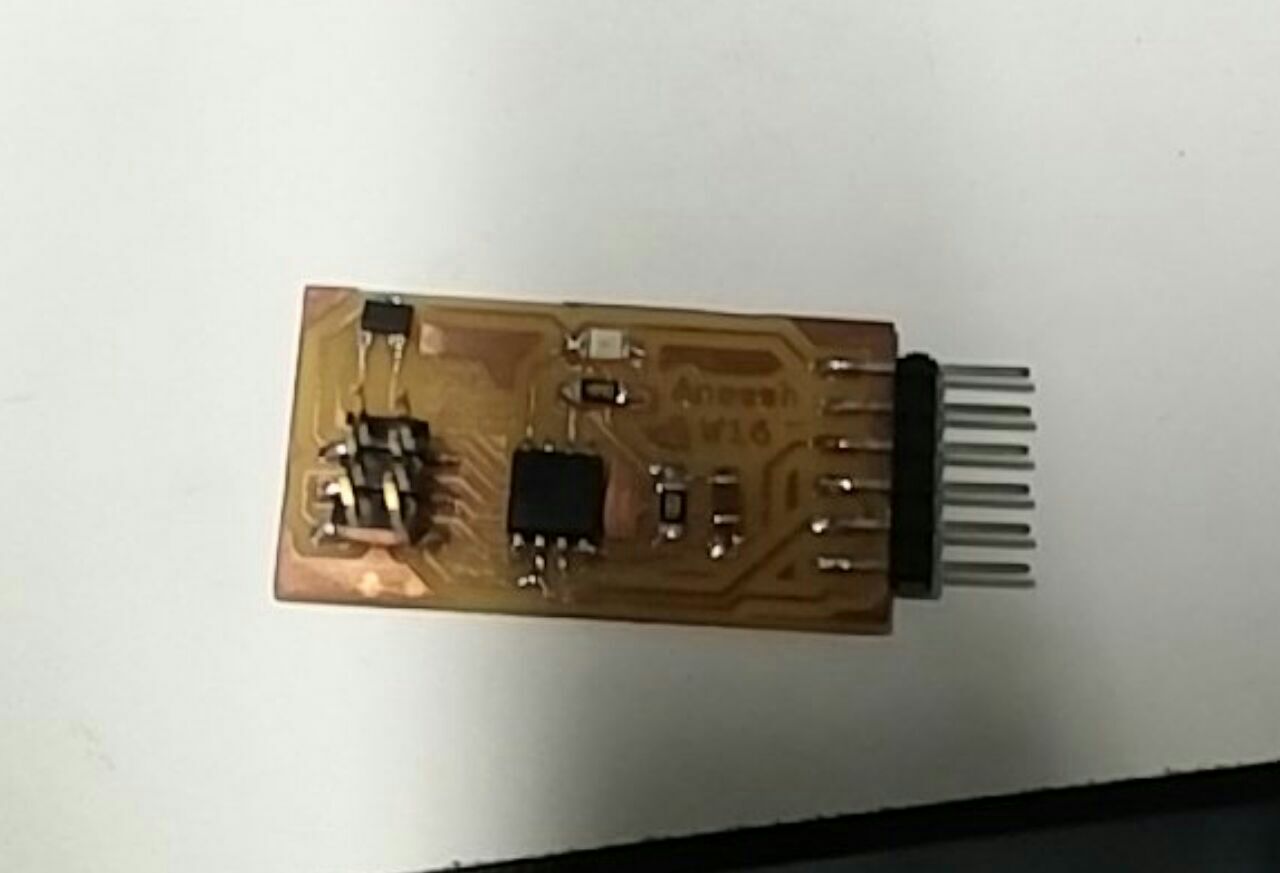
After stuffing the board I programmed the board.
I flashed Niel's program initially.
Then using arduino IDE did a simple programs such as glowing of LED when Hall sensor detects a magnet.
Serial Communication
For this, I connected the board to laptop using FTDI cable.
FTDI connected to board.
I used arduino IDE for communication monitoring.
I opened arduino and opened serial communication monitor window through and CNTL+SHIFT+L.
I was only using the arduino board as an 'FTDI' replacement
After flashing the programs I checked the working by bringing the magnet near the sensor.
Results are shown in the videos below.
Testing the interface
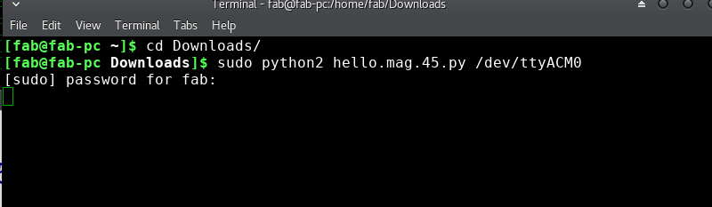
Ran Niel's python script in my PC.
Here, I was only using the arduino board as an 'FTDI' replacement.
Problems Faced
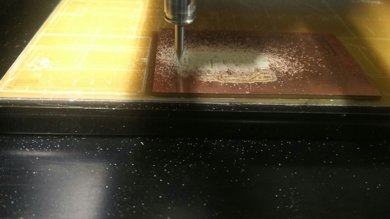
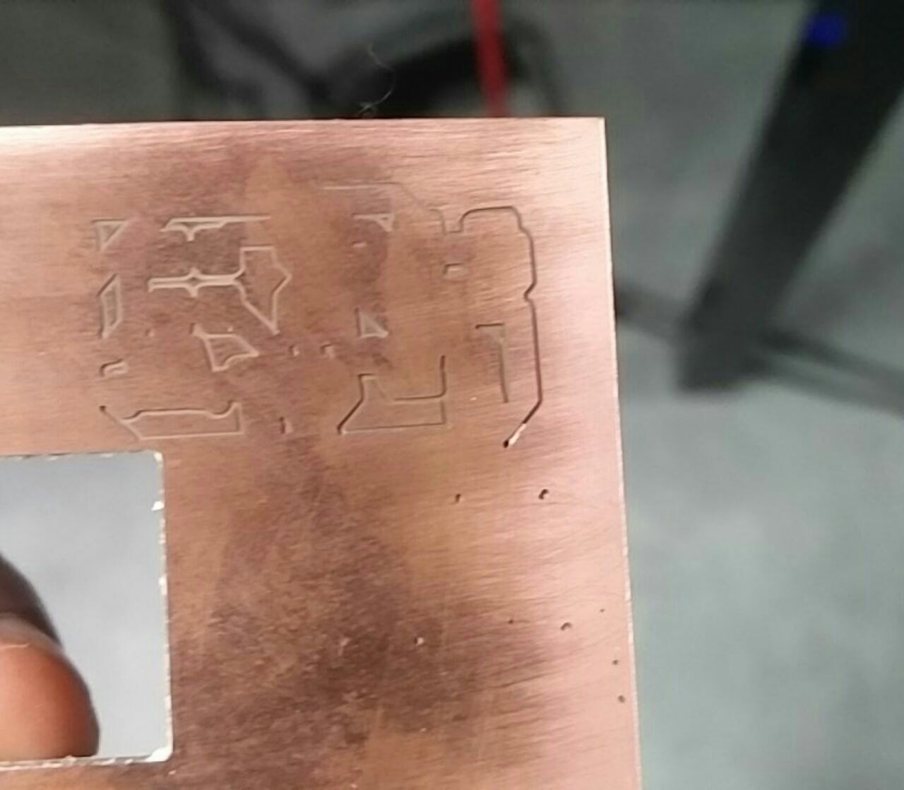
While milling the board I found that the 3D plotter was not milling the board properly.
So I aborted the operation and changed the intensity to 0.12 from 0.1. Also changed the position of the board on the sacrificial layer as there was a doubt of slight inclination on the bed.
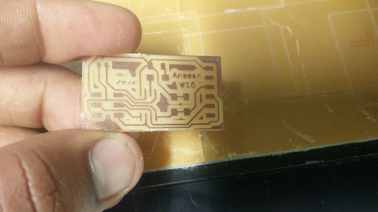
Milling on the other side gave me a better result.
While programming I didn't get the required result.
I thought it was due to the FTDI cable I was using - which was of 3V rating and I needed 5V!
After consulting with my instructor, Sibu ; I soldered the IC once again, even though while checking for continutiy using a multimeter gave me positive results, Sibu asked me to solder the 3rd pin again.
I did this and finally the board was working.
Conclusion
This week was learning about input devices.
I went through basic things about the input devices.
The most notable thing that happened this week is that, I was able to route the whole circuit easily and without any zero ohm or jumper wires.
Another thing is that the size of the board milled was very small.
Minimal size.
And also,the soldering was better and I got quicker at it.
Design Files
The schematic, board design png files of the Board can be found here.
The png files of the Board can be found here.
The program files of the Board can be found here.