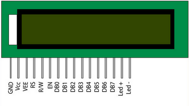
 pin diagram
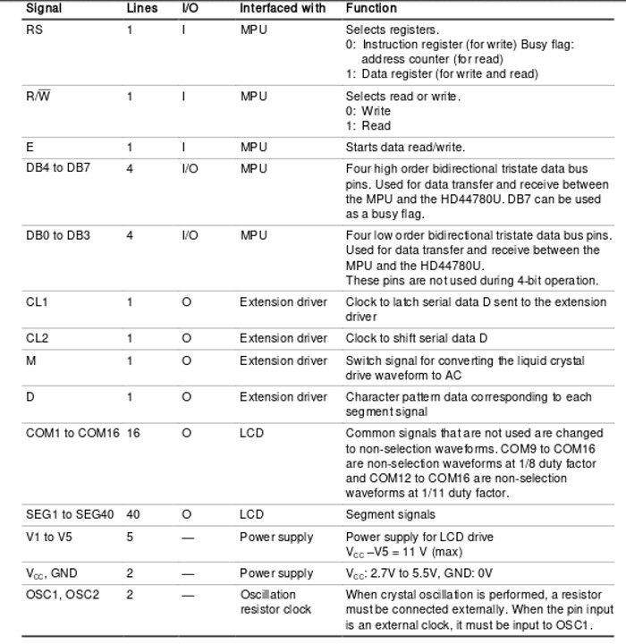
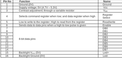 Pin description
Pin 1, 2 and 3:-
First pin is Gnd. Second pins is positive supply pin. Third one is Vee pin, this pin is used to control the contrast of LCD.Pin 4 (RS):-
This is register select pin. The LCD have two operating modes, instruction and character mode. Depending on the status of data ( 0 or 1) on Pin 4 (RS), the datas on 8-datas pins (DB0 to DB7) are treated as instruction or chracter. The instructions like clear the display or move the curser is set by instruction mode when pin 4 (RS) is set to Zero. For character mode, the RS pins is set to high (one).Pin 5 (RW):-
This pin is the read write pin. If you want to provide data to the register, you need to provide logic low to this pin and if you want to read from the register, you need to provide logic high.Pin 6 (EN):-
This is enable pin. It allow to send data to data pins when high to low pulse is given in this pin.Pin 7 to Pin 14:-
These pins are called 8-bit data pins. HD44780 chipset LCD's can be run in two modes, either in 4 bits or 8 bits. 4 bit requires 7 input/output(D4,D5,D6,D7,RS,EN,RW) pins and 8 bit mode requires 11 input/output (D0,D1,D2,D3,D4,D5,D6,D7,RS,EN,RW) pins. Obviously 8 bit mode is twice as faster than 4 bit mode.Pin 15 and Pin 16:-
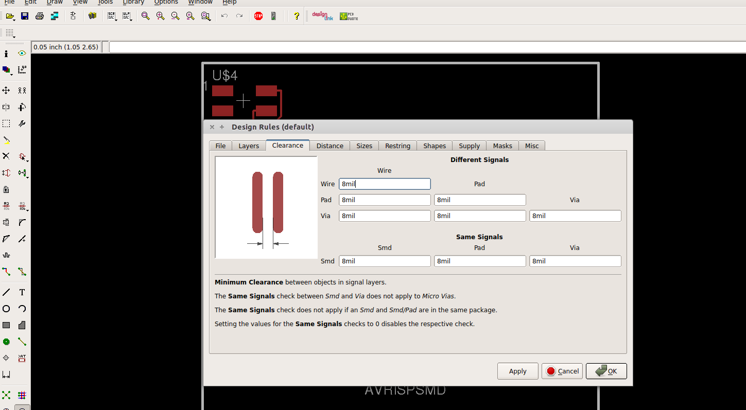
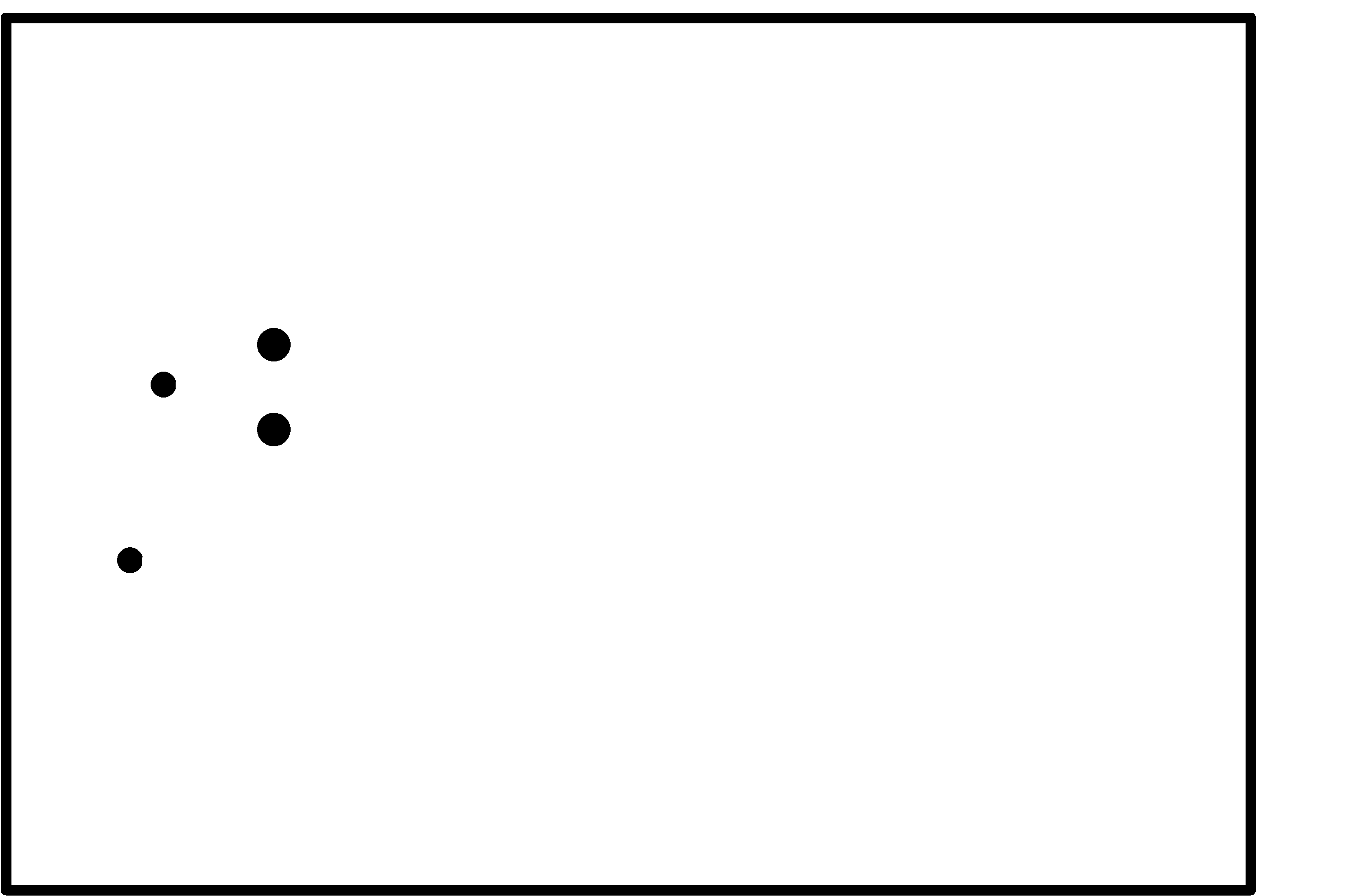
These are the power supply (5v) for backlight LED. I decided to try EAGLE this week as I had used Kicad for designing the PCB earlier. The schematic diagram and its PCB is shown below.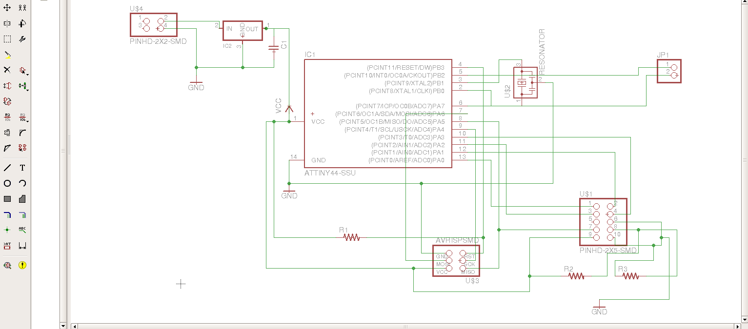 The schematic diagram
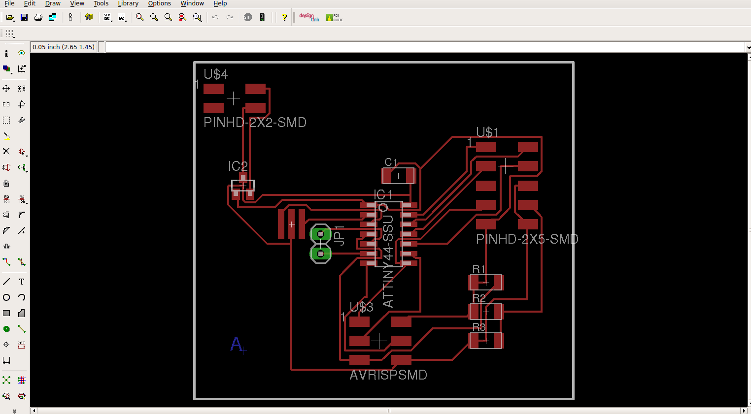
When I consulted with my instructor Sibu, he said it is better to re-route as the routes between the pins of the IC might not come as desired and it might short the board.
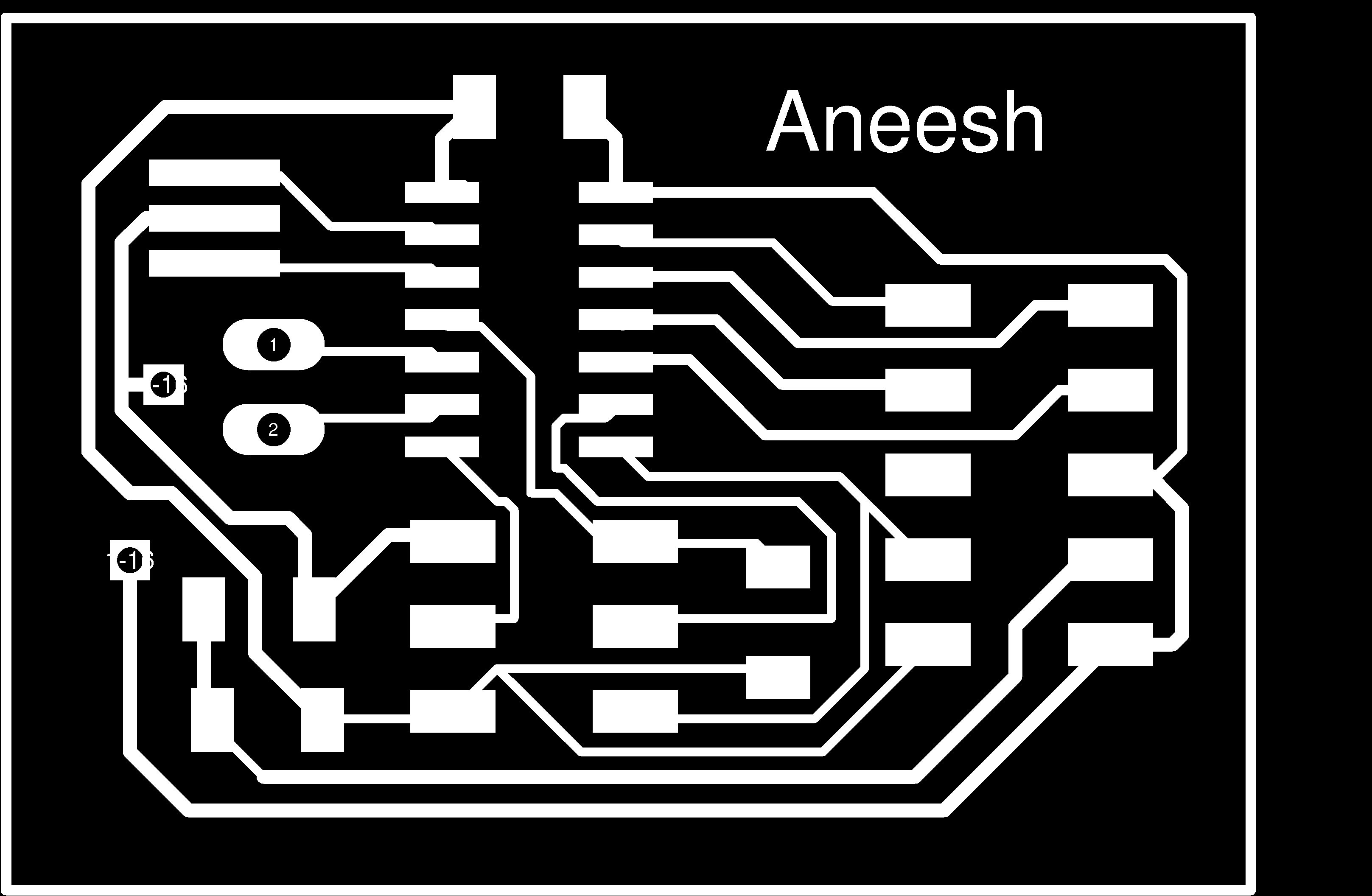
So I re-routed the board and here's the final image.
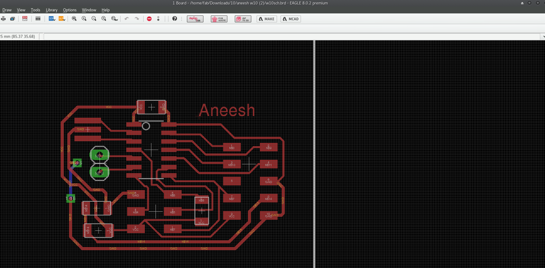
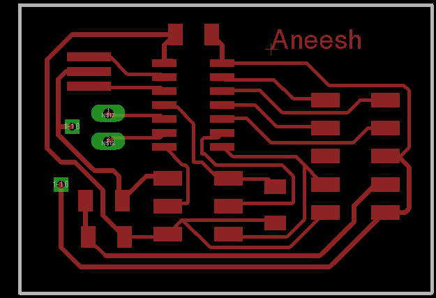
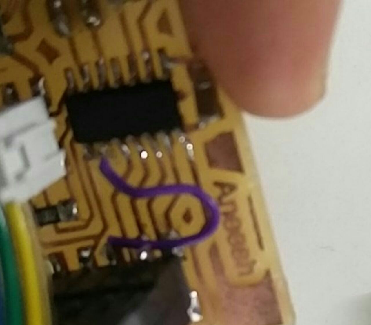
I had to use a jumper as I couldn't solve it fully. I used it on the backside of the board (the green wire as shown).
I used a 2x2 Header and soldered it to two free pins of the IC for future use, if and when required. It was connected to the IC pins as shown in the board layout. Then I milled and cut the board.
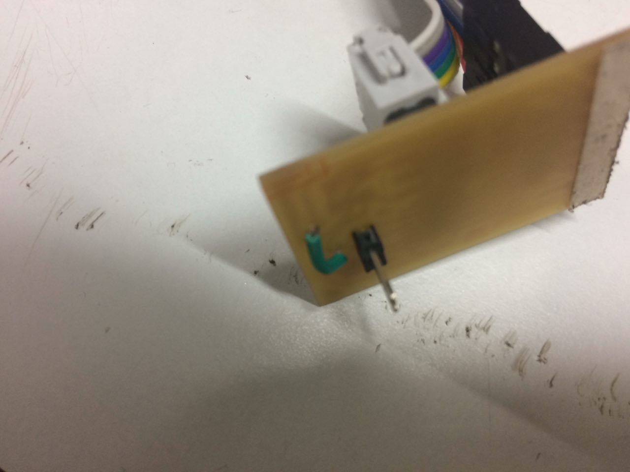
The board was cut and I started soldering.
Components Used
- AtTiny44a
- Capacitor 1uF
- Resistor - 1K, 10K and 100K
- 2x5 Header LCD
- 2x3 ISP header
- Resonator XTAL1 20MHz
After soldering the board I found a major mistake I made. One route was not there!! PA4 of the IC should've been connected to Pin 6 (EN) of the LCD. This was not there. So I connected it using an external wire.
Then I thought of checking the continuity of points on the board. I took the multimeter and started checking it. Another problem I found was that one of the pins of the IC was not soldered properly. So I soldered that pin properly. Now the board was ready to use.
Programming
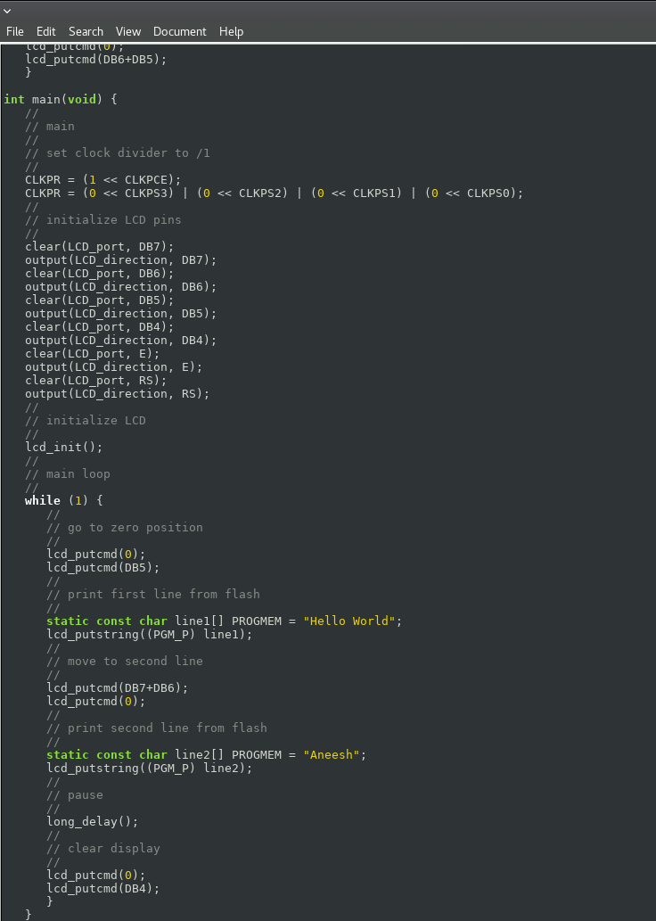
Programming was never my strength area. I decided to use Niel's program to check my work. I modified the message on Niels program, and checked it. Thankfully it was working fine.
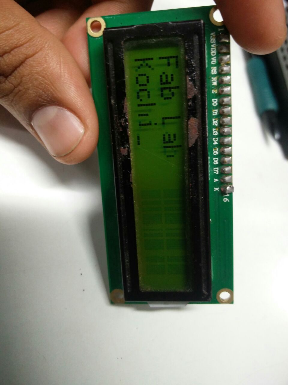
Changed the display messege in Niel's board as shown in the figure below.
Flashing the program
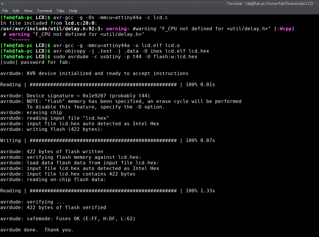
Changing the fuse
To switch the external clock low fuse was changed. For some operations we might need higher frequencies. So I just tried changing that as well.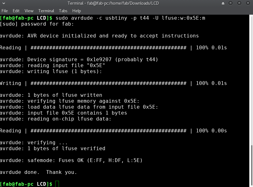
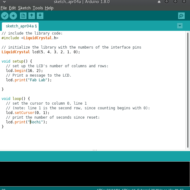
Then I tried Arduino. Even in the previous weeks I found arduino bit more simpler, easier to code and understand.
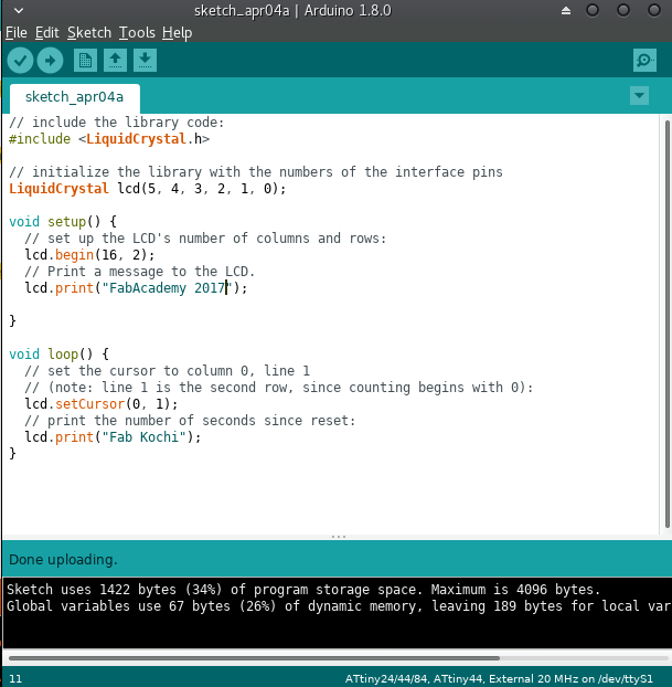
Then I tried a few messeges and it was displayed perfectly.
Final Thoughts
Even though my first soldering experience was surprisingly succesful, after that it was not that great.
This week my routing had some problem, I had to re-route. Other than this I had to connect a wire from one of the pins of the IC to the LCD's pin.
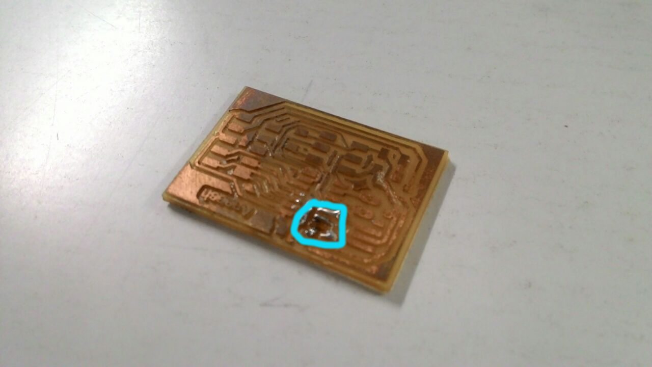
Even though I managed to cut a very small board this time, compared to the last board I made, during soldering some copper in my the first board got peeled off.
I was not able to fix the IC's pin in that portion. Hence I had to mill another board.
 Next time I've to try and do this in the first go and without any errors!
File Downloads
The design files of the board can be found here
The mill and cut files can be found here
The C program files are available here here
The arduino program file is available here