
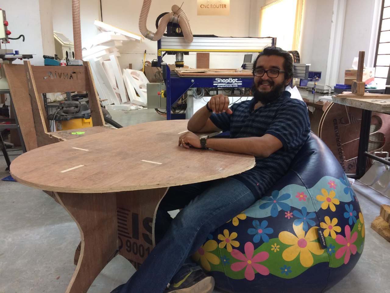
Fab Table is a multipurpose table which will have various features that can be developed in the fab lab.
Even though there were a few ideas & the thought of a lab-group project were there, I finally decided on the first idea I thought of making, a FAB-Table. Over the period of the course,week after week, new ideas were coming to my mind. From just a dismantlable table, after every week I decided to add other things as well - Usage of other machines in the lab. Some smart furnitures has inspired me in the process of choosing this as my project. Even though I had a lot of plans, due to hectic schedule and lack of time I couldn't make everything I thought of.

This was just the initial plan. Upon searching the net I got various ideas & wanted to explore some things.
Then I wanted to add a movable portion for keeping monitor.
I got this idea from this video
These were the initial stages - and as the academy was going on in full fledge I couldn't do much research.
Unfortunately I fell sick for a week just before the presentation, so I had very limited time to complete everything.
Finally I decided on a FAB-TABLE with a capacitive touch board, which can adjust the brightness of the LED strip attached upon touching.
FAB TABLE is a smart furniture that can light up when motion of user is detected when a PIR sensor is added, and the brightness of the strip can be controlled.
Most of the components are available in the lab itself.
18mm Plywood (Rs. 1500)
Sensors, PCBs, wires and battery (Rs. 500)
LED Strip (Rs. 450)
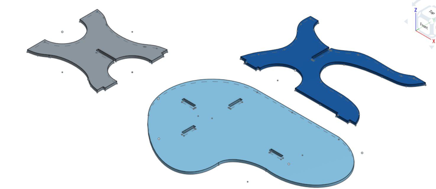
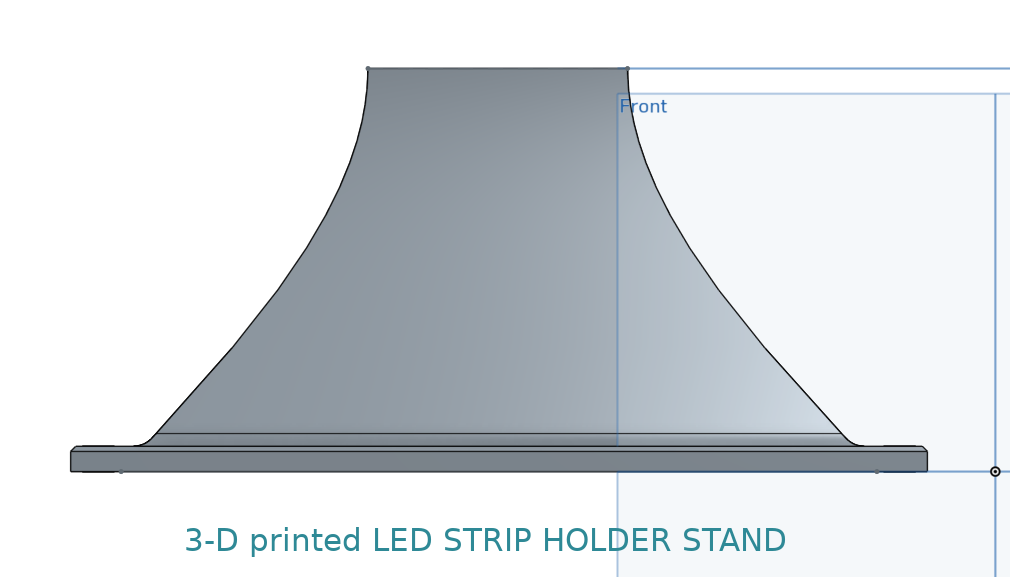
3-D printed holder - ABS and PLA (Rs. 1500)
Laser-cutted stand / boxes for keeping the sensors and battery (Rs. 275+85)
Total = Rs. 4310 (can go up to 5k-5.5k.) (Around $65-$70)
For keeping the electronics board I decided to make a laser cut box. The base will have a cut for the touchpad board, as the connections are taken out through this. This also helps in removing the mess of wires.
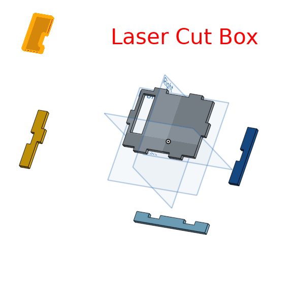
This can be easily stuck under the table as well, if needed.
Vinyl cutter is basically to decorate the table with stickers.
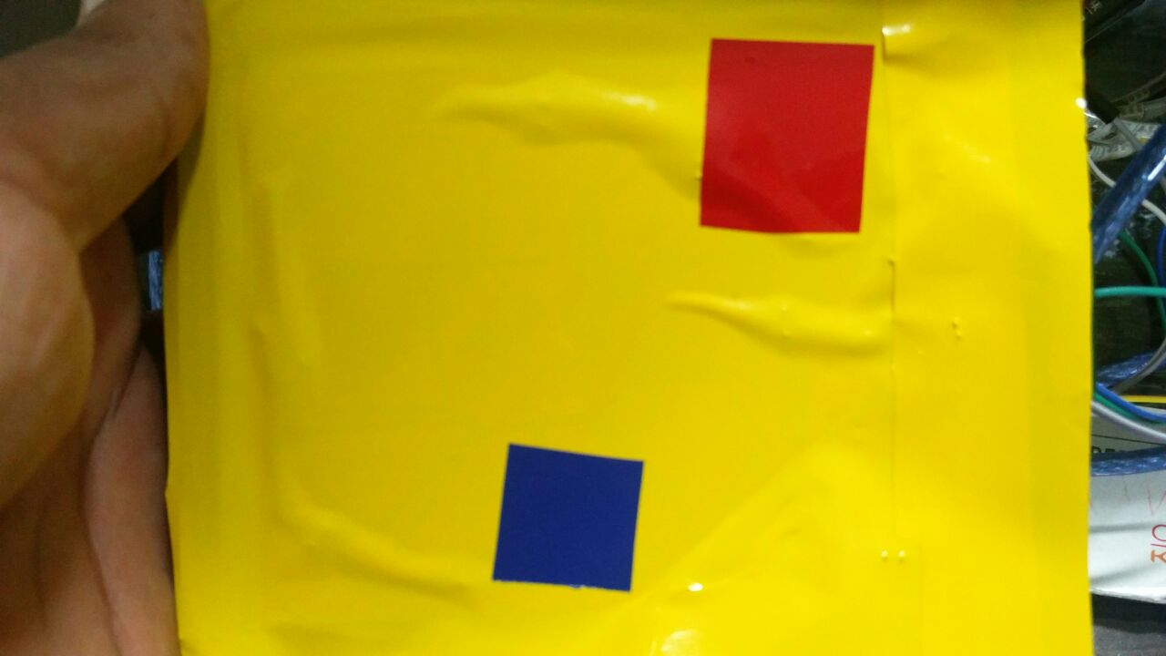
I've also used vinyl stickers on my touch pad board as well.
These stickers cover the joints on the table. It is not seen outside because the stickers cover that portion.
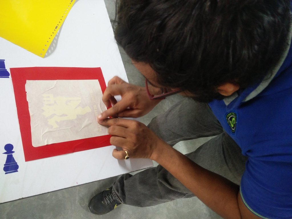
The two stickers indicates the brightness - high low states. Red increses brightness and blue decreses the brightness of LED strip. This can be identified easily because of the stickers.

3D Plotter & Electronics work bench - For milling and soldering the boards.
Embedded programming - To program the board.
I made a satshakitfor completing my project. The touchpad board is connected to the LED strip, battery's ground and to the IC.
I designed the satshakitusing EAGLE. To the original satchakit, the old student made I added ftdi port and isp header's port.
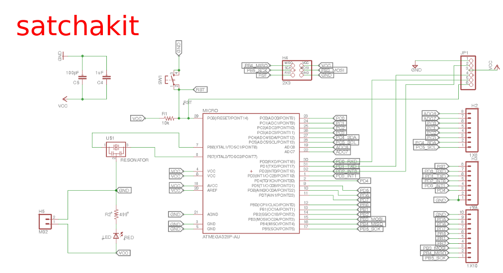
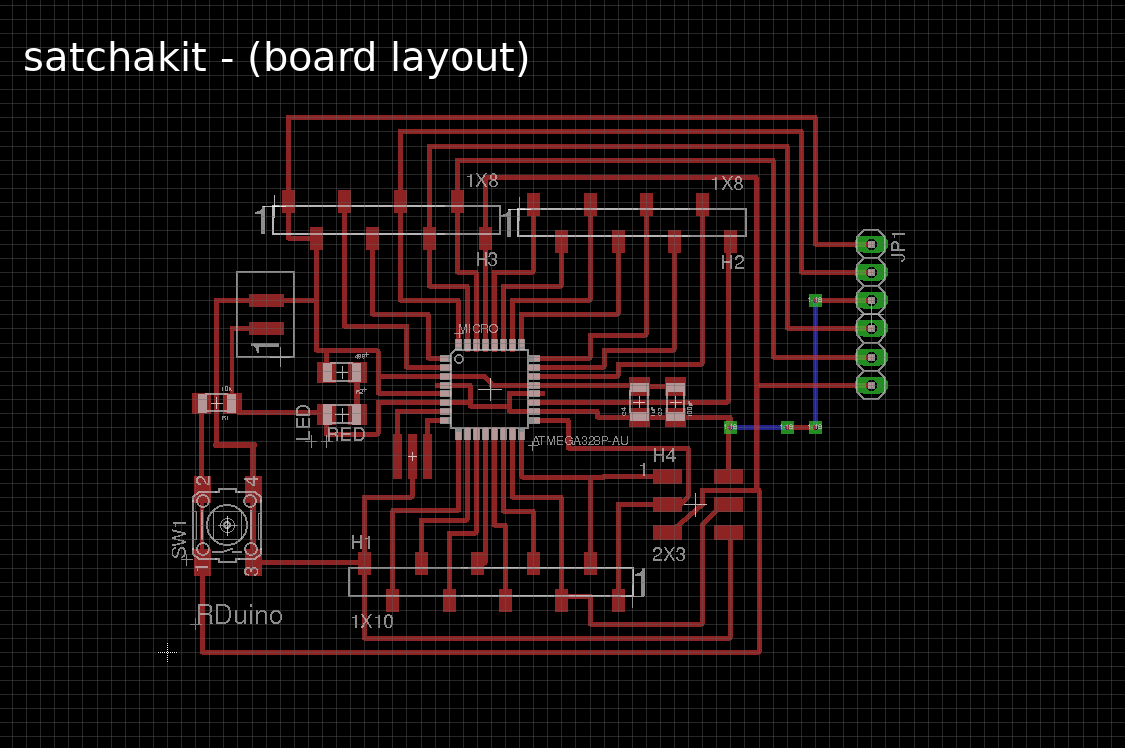
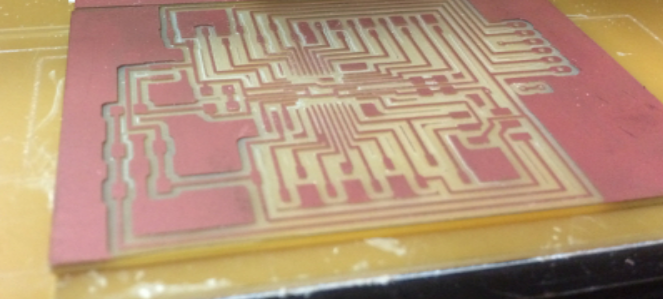
The board trace and Cut out are as below.
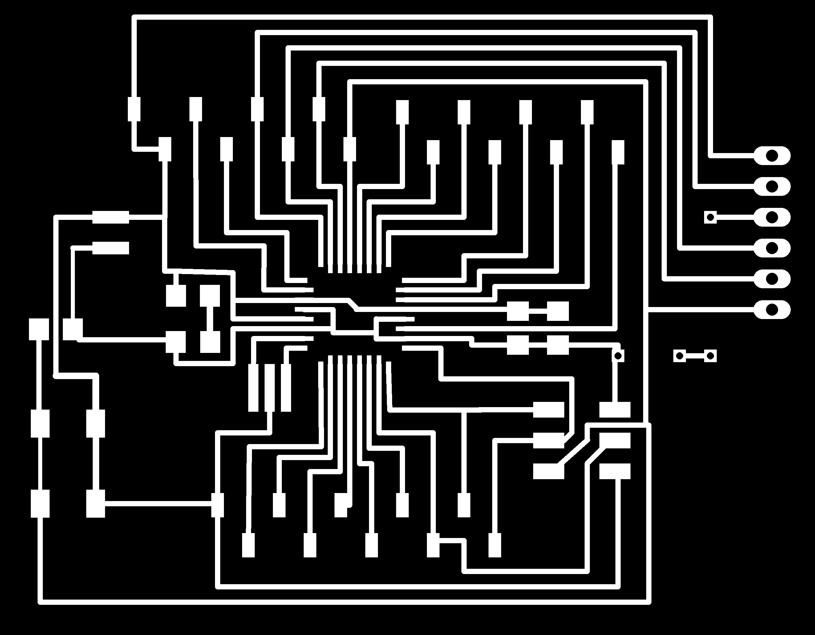

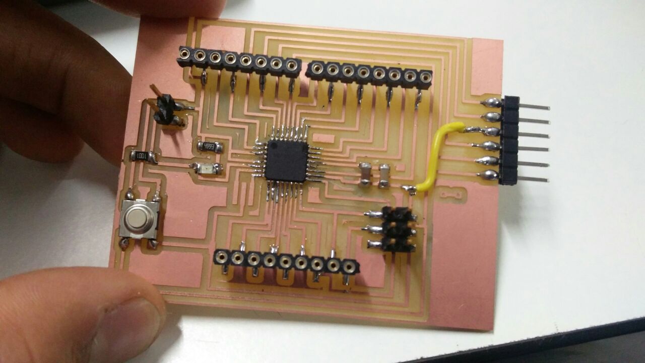
After milling.
satshakitbasically works like an arduino.
Using satshakithelps in adding whatever we want later as it has many ports. In case if I want to add a display or some sensors, this can be easily done.
For me, this is the toughest part.
In order to program the board, I had to refer and take help from others A LOT.
With no coding background I really found it difficult to do the coding.
First of all I did the basic ON - OFF programming using capacitive touch.
Then the program to increase and decrease the brightness.
Before assembling everything I tried to run the program using arduino first and then I used my satchakit.
I connected the LED strip,battery,satshakitand the touchpad together and did the initial try.
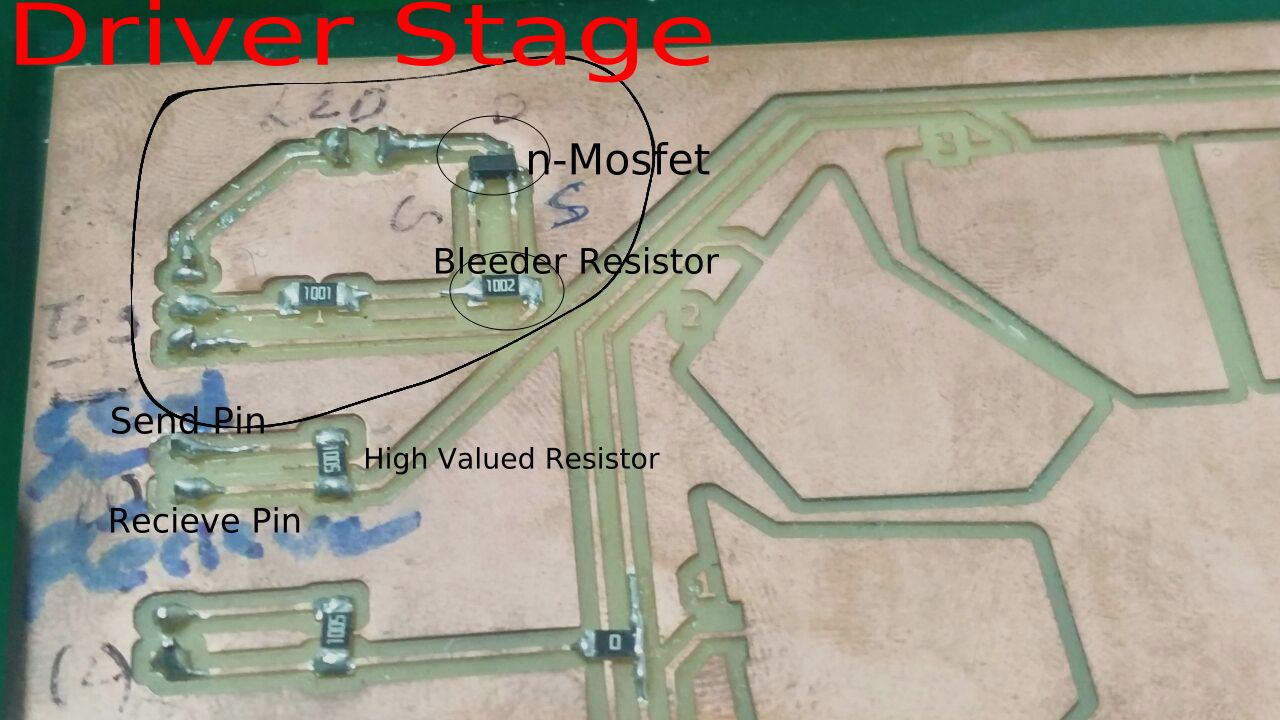
The capacitiveSensor method toggles a microcontroller send pin to a new state and then waits for the receive pin to change to the same state as the send pin. A variable is incremented inside a while loop to time the receive pin's state change. The method then reports the variable's value, which is in arbitrary units.
The physical setup includes a medium to high value (100 kilohm - 50 megohm) resistor between the send pin and the receive (sensor) pin. The receive pin is the sensor terminal. A wire connected to this pin with a piece of foil at the end makes a good sensor. For many applications, a more useful range of values is obtained if the sensor is covered with paper, plastic, or another insulating material, so that users do not actually touch the metal foil. Research has shown that a small capacitor (100 pF) or so from sensor pin to ground improves stability and repeatability. When the send pin changes state, it will eventually change the state of the receive pin. The delay between the send pin changing and the receive pin changing is determined by an RC time constant, defined by R * C, where R is the value of the resistor and C is the capacitance at the receive pin, plus any other capacitance (e.g. human body interaction) present at the sensor (receive) pin. Adding small capacitor (20 - 400 pF) in parallel with the body capacitance, is highly desirable too, as it stabilizes the sensed readings.
For understanding the concept, especially the coding part this link helped a lot. The coding was made easy mainly because of the library that was available in the above link.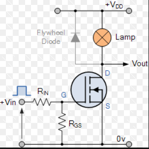
In the circuit arrangement an Enhancement-mode N-channel MOSFET is being used to switch a simple lamp “ON” and “OFF” (could also be an LED). The gate input voltage VGS is taken to an appropriate positive voltage level to turn the device and therefore the lamp load either “ON”, ( VGS = +ve ) or at a zero voltage level that turns the device “OFF”, ( VGS = 0 ). If the resistive load of the lamp was to be replaced by an inductive load such as a coil, solenoid or relay a “flywheel diode” would be required in parallel with the load to protect the MOSFET from any self generated back-emf. This is actually a very simple circuit for switching a resistive load such as a lamp or LED. But when using power MOSFETs to switch either inductive or capacitive loads some form of protection is required to prevent the MOSFET device from becoming damaged. Driving an inductive load has the opposite effect from driving a capacitive load.
The micro-controller can be powered by 5V.
But the LED strip will not work with 5V.
It needs 12V - but works with a 9V battery as well.
So here, I'm using a 9V battery to power the LED strip.
The battery is connected as shown in the hand-drawn schematic below.
Also, I'm using a 5V regulator to power the micro-controller from the battery.
Here, the MOSFET's GATE is connected to the MICROCONTROLLER.
This is where the triggering pulse comes.
DRAIN is connected to the LED.
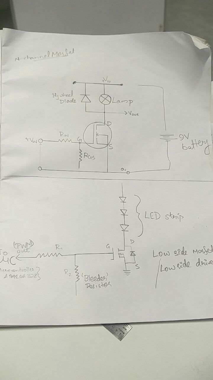
Here the MOSFET I used is N-Ch 30V 1.7A. I used a 9V battery to power it. If I had used a source with more rating I might have had to change the mosfet's value. Instead of the above mosfet - I would've had to use N-CH 50V,16A.
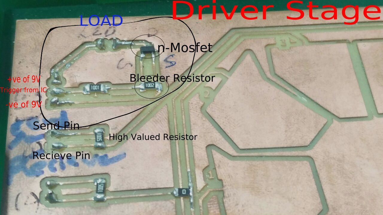
 This is how the FET is connected to LED strip
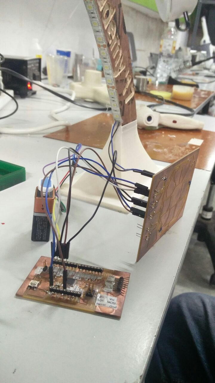
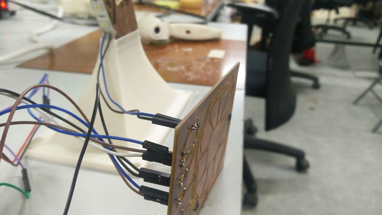
This is the whole connection. The Board is powered using ribbon cable, which will be connected to PC or with a battery.
#briefed as per the program written. Should be changed if the pins are changed.
The n-channel mosfet is connected to a 1x2 and 1x3 headers.
The 2 touch pads have a send and a recive pin. (here I've taken pad 1 and pad2 for the brightness control).
The trigger pin of the 1x3 header (in this case the middle pin) is connected to the LED pin defined (here it is 9).
2nd pin of the IC is connected to receive pin of 1 in touchpad.
3rd pin of the IC is connected to recieve pin of 2 in touchpad.
4th and 5th pin of IC to send pins of 1 & 2 respectively.
1x2 header connected to drain - LED's 2 pins are connected to this.
Ground is common - ie, -ve of battery , source of mosfet and ground of the satshakit are connected together. Drain is connected to the 12V supply.
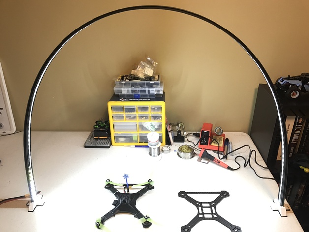
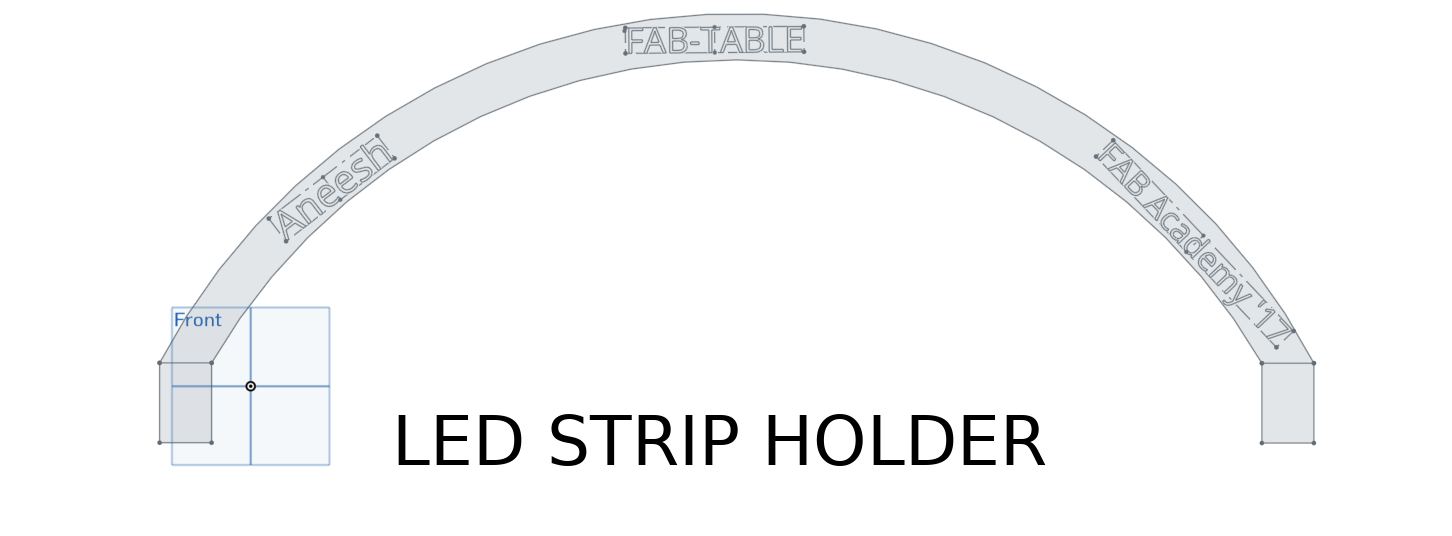
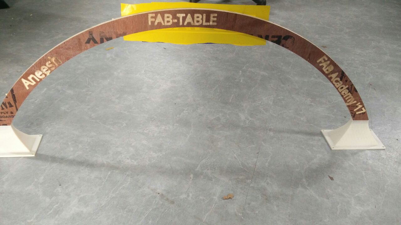
After testing it, I stuck the LED strip to the strip holder I made using Shopbot and covered the touch pad with vinyl sticker. The red sticker indicates brightness increase and blue indicates brightness decrease. This is shown in the video below.
capacitiveSensor and capacitiveSensorRaw will return -1 with an invalid choice of pin parameter, but it appears that this feature is not working at this writing. Engineers are working on this, stand by...
capacitiveSensor and capacitiveSensorRaw will return -2 if the methods timeout. This is caused by the count exceeding the value of CS_Timeout_Millis, which is set at a default value of 2000 milliseconds (2 seconds). This is most often caused by a missing resistor or the resistor in the wrong pin. It could also be caused by a sensor that is grounded or connected to +5 V.
A timeout is necessary because the while loop that does the timing in the CapacitiveSensor method, will lock-up the sketch (the function will never return) if, for example, the resistor between sendPin and receivePin becomes disconnected.
I was initially planning to make the capacitive touch control in such a way that moving my hand clockwise or anticlockwise will change the brightness. That is why I made 9 pads in total. But I couldn't make it happen as at a time only 2pads worked. I searched through the internet for solutions and various reasons were said. One being that - the non-uniformity in the area of the pads. Another issue I faced was that, initially the response was very low. I had put a 100K resistor. Then I decided to increase the value of the resistor. I used 10M and the sensitivity was awesome!
Points to note

FAB TABLE by Aneesh S Krishnan is licensed under a Creative Commons Attribution-ShareAlike 4.0 International License.