Computer-Controlled Machining
Tasks:
Make something big (on a CNC machine)
Describe the workflow (setting up the machine, using fixings, testing joints, adjusting feeds and speeds, depth of cut etc)
Described problems and how you fixed them
This week assignment is about big machining and we have to Make Something Big.
Because this assigment will require a lot of time, as well as money, the material is expensive in Germany, I would like to make something which I will use at the end. The idea is to make a Coffe Table, which I would like to place in our FabLab. To be creative, I will build a table in the shape of a guitar tip, the part where the strings are connected! So Let's get started...
I will use my favourite software  , to create the design of the table. I was inspired by the Fender guitar tip, which looked really nice, and I will try to replicate it!
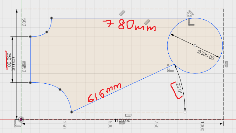
I start with a simple rectangle, which will be the reference working area, which means the dimensions of my table should not exceed this area. The dimensions are 600mm x 1100mm

Using simple shapes like circle, lines, and spine lines, I create the model of my table which looks like this:
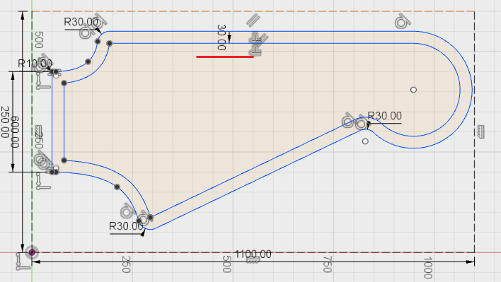
I also wanted to have a smoother shape, that is why I make some Fillets at all the corners. I used the radius of 30mm for some corners, and 10mm for some others:

While I was designing, a cool idea came to my mind! To add some more spices to it, I will place on top of the table a sheet of acrylic. It will make the surface of the table totally flat, as well as give it a visual sexiness :p
I decided to make a small Offset of 30mm and place the acrylic sheet in the middle!
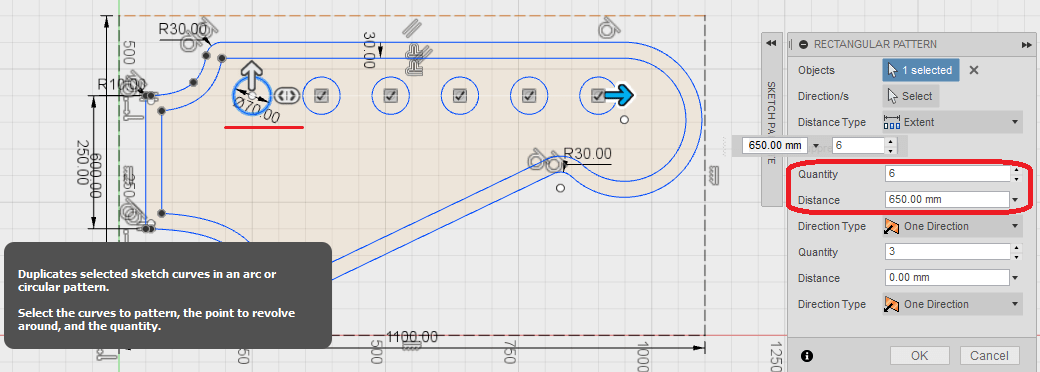
Now I want to add the decorative holes, the part where the strings are connected to the guitar. I do not think that they will have any use, but this will make it easily recognazible that this is a part of a guitar!
I drew a circle with the diameter = 70mm, and using the Rectangular Pattern I make six holes equally distributed from each other.
And now I extrude my sketch by pressing E button, and extrude it by the thickness of the material I am planning to use (18mm in my case). The inside offset part, I want it to be 3mm engraved, because I will place a 3mm acrylic sheet on top of it, that is why, I extrude it by 15mm (18mm - 3mm). The holes for the strings, I want them to be 1mm inside the engraved offset, which means I extrude it by 14mm (18mm - 3mm - 1mm)
Now I want to make the joints for the legs. I change the view to Back, and design the joints on the back side of the table by creating a New sketch. The idea is to make the joints look like a cross. Using simple lines, and takig into account the thickness of the material, I designed the joints.
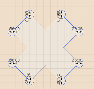
And here comes the Limitation of the CNC machine. The tool diameter of the machine is 4mm and the tool has a rounded shape, and because I want the joint to have a 90deg. angle, I have to make something called Pockets. This will allow the tool to go inside the pocket, and will leave the joint with a 90deg. angle.
To be on a safe side, I made the pockets of 6mm diameter, starting from the corner of the cross, and then trimming the unnecessary lines.
And this is how I decided to place the joints:
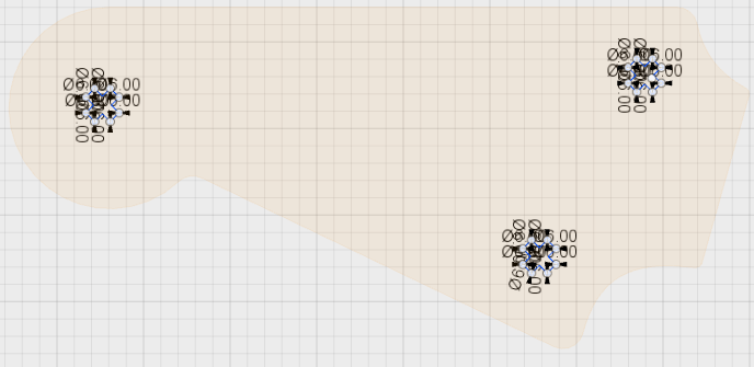
I tried to place them in a way that the load on the table will be distributed equally.
I did not want to have a through cut, because I wanted to keep the top face of the table the way it is, that is why, I had to kind of engrave this joints half way through. I extruded them inside by 10mm. According to my calculations, I have 18mm material thickness, minus 3mm engrave offset on top, minus 1mm holes, and I am left with 14mm. If I go 10mm from the bottom side with the joints, I still remain with 4mm safety material!
To have a joint of 1cm inside, 18mm material thickness, I gues it is gonna work! Hope that it will be enough for the table to be strong and stiff.
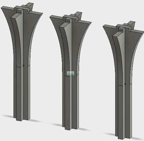
Next I have to design the legs. I started with the joint, which is 18mm thick,10mm high, and 50mm wide. I measured the length of an existing coffee table, and tried to keep the dimensions. So the total length of the leg without the joint is 400mm
Next to the joint on top, I tried to widen the area of the leg, and increase the stiffness of the structure. This is how it looks:

After I extruded the sketch by 18mm, I converted the new bodies into Components. This will allow me to assemble them, and have a visual representation of whats happening! In the Assemble menu, I choose Join, and select the points of each component which I want to join. Before doing that, I have to turn the component at 90deg. by using the Move command
I also copied the whole thing, because I need 3 legs in total. This is how it looks:
And these are the parts that I get at the end, the actual table, with the joints on the back side, and the legs:
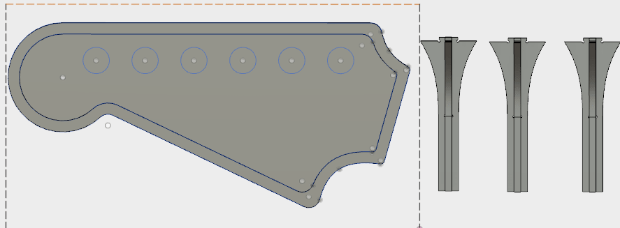
After I double check all the dimensions, make sure that everything fits, I export the sketches as .dxf file for further proceedings.
Let's mill it!
To cut my design, I will be using the big CNC monster.
A CNC (computer numerically controlled) is a machine that uses a cutting bit that rotates at a very high speed to remove material from a part.
The machine reads a pre‐programed computer file telling it where and how to cut, usually .GCode file. A cutting bit is rotated at a very high RPM by a spindle motor, which can move the bit up and down. This mechanism is moved left, right, front, and back by a cross arm. The machine is therefore known as a three‐axis router because it can move on the X, Y & Z axis. The machine can do two dimensional cutouts and etching, as well as three‐dimensional relief work.
In FabLab Kamp-Lintfort we have a CNC portal milling machine by e(sign: Easy Worker MasterPro 2513.
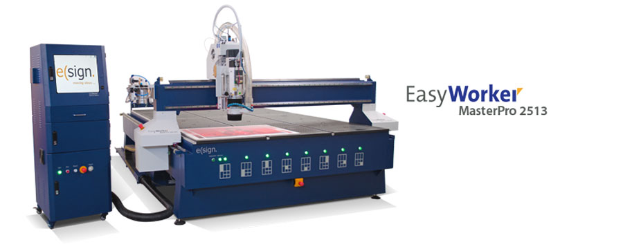
It’s working area is 2600 x 1400 x 300mm and it comes with a vacuum table. We primarily use it for wood milling but with its HSD Spindel (3.9KW; 24.000U/min) it is also capable to mill metals easily.
The material which I will be using is 18mm Plywood
At first, I place the wood sheet on the CNC bed, and after I aligned it, switch on the vacuum. After I exported the .dxf file, I used  to edit the design before importing it into the machine CAM software. Because I was planning to do a double side job, the important thing was to keep the same position while flipping the wood, which is kind of hard to achieve!
To acomplish this, we used a little trick, which consists of making reference holes. So this is how it works:
In Rhino3D I designed 4 holes at each of the corners, where I set my Zero X and Y axis. And the idea is that after I flip the sheet, I set the zero again inside the hole!
To set the X,Y and Z Zero Positions, I home the machine by pressing the home button in the software (or on the remote control).

At first, I can set my zero X and Y roughly aligned to one of the corners of the bed. We also tried to use the laser for this, but all the time when simulating the process, it was showing collisions, because the zero was going out of the working area

Now I have to find the Z axis, which I do using the special tool which comes with the machine:
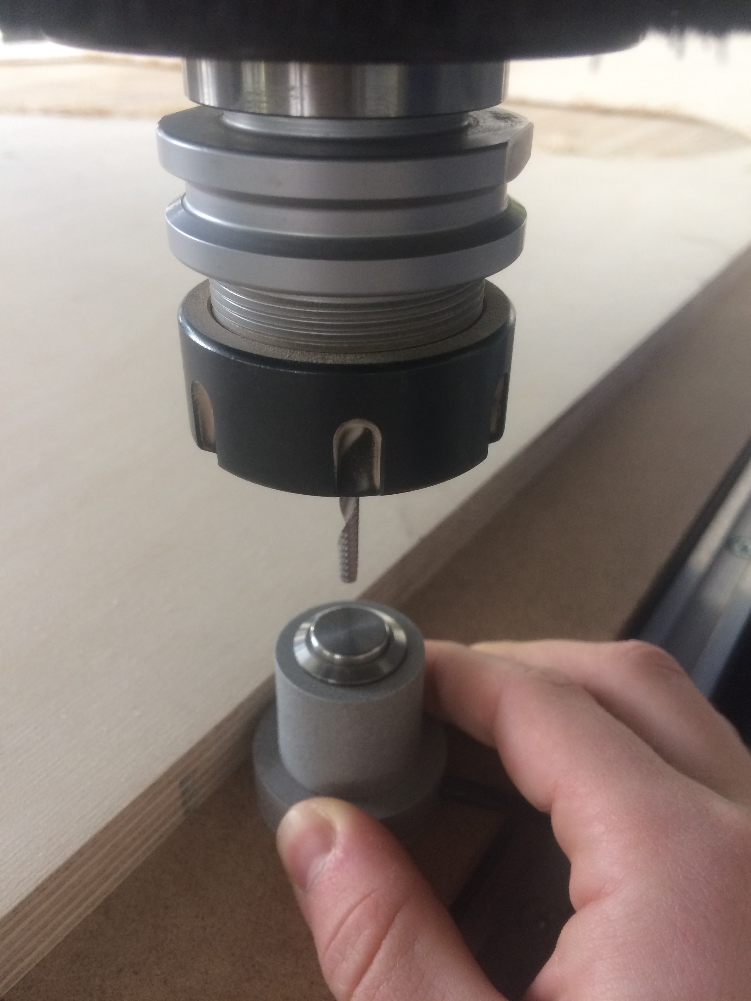
Important thing is to place it on the bed of the machine!
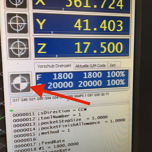
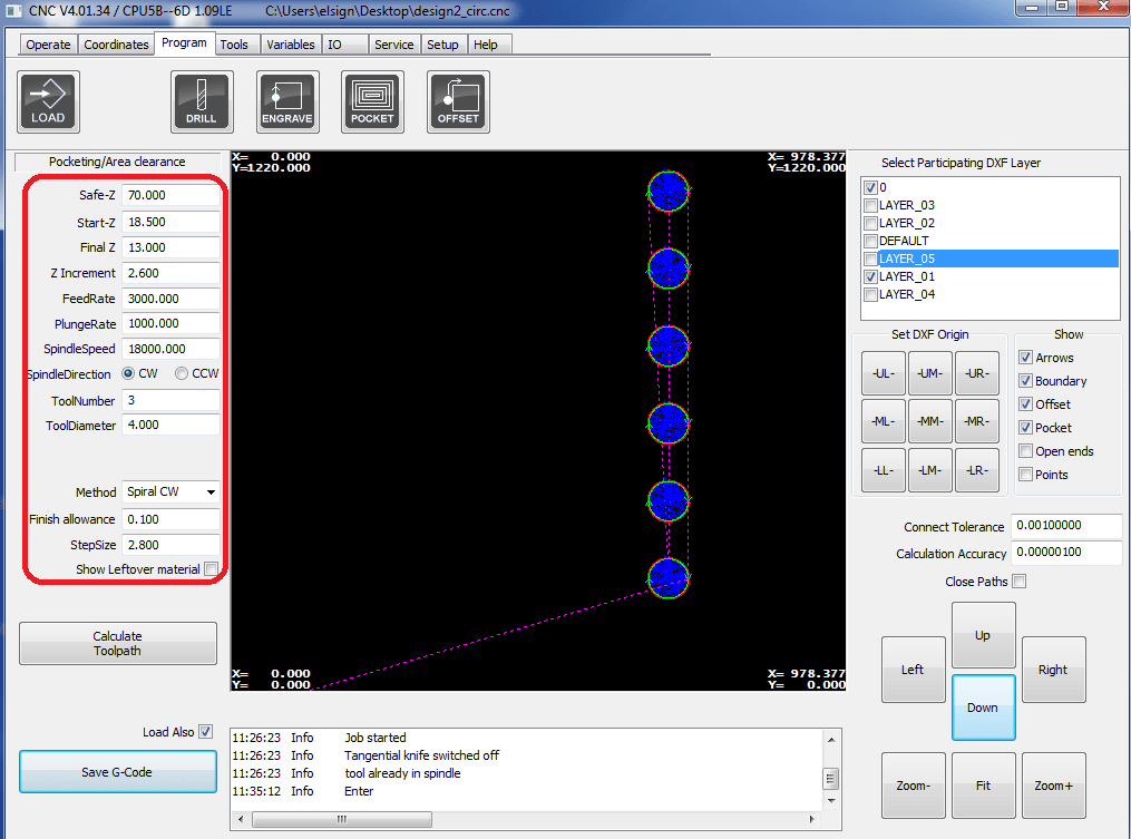
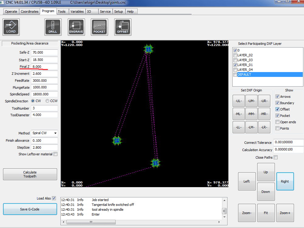
Now I can launch the first job, which is making the reference holes. These are the settings which I used:

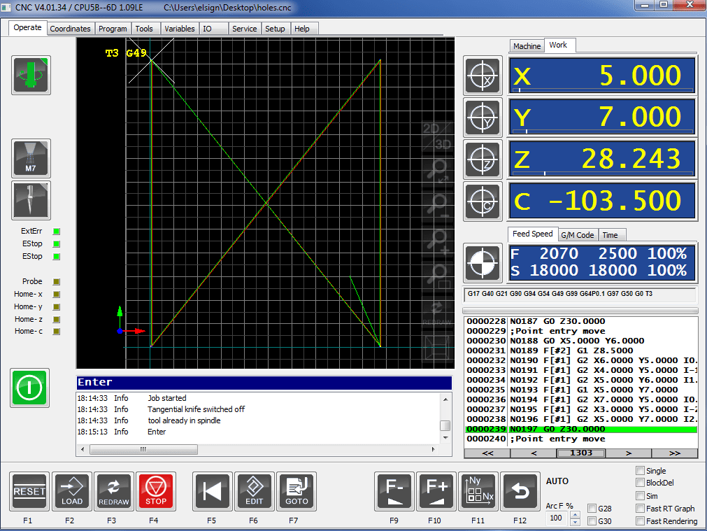
I press Calculate Toolpath to simulate the job and make sure that there are no collisions! After I save the .GCode, and launch the job, I get this window:
After the machine finished the job, I can choose the new X and Y axis, by placing the tool right in the center of the hole

Before cutting the actual design, I decided to make a small test, to see the outcome. In Rhino3D I made a small design of a square, engraved by 3mm, and a circle in the middle engraved by 1mm more. Exactly the test of what I was planning to do in my design. This is what I get:

After the test, I can be sure that I have the right Zero, I have the right settings, and I can launch my actual design.
I will start with engraving the offset on the upper part.
Here is a short video of the process:
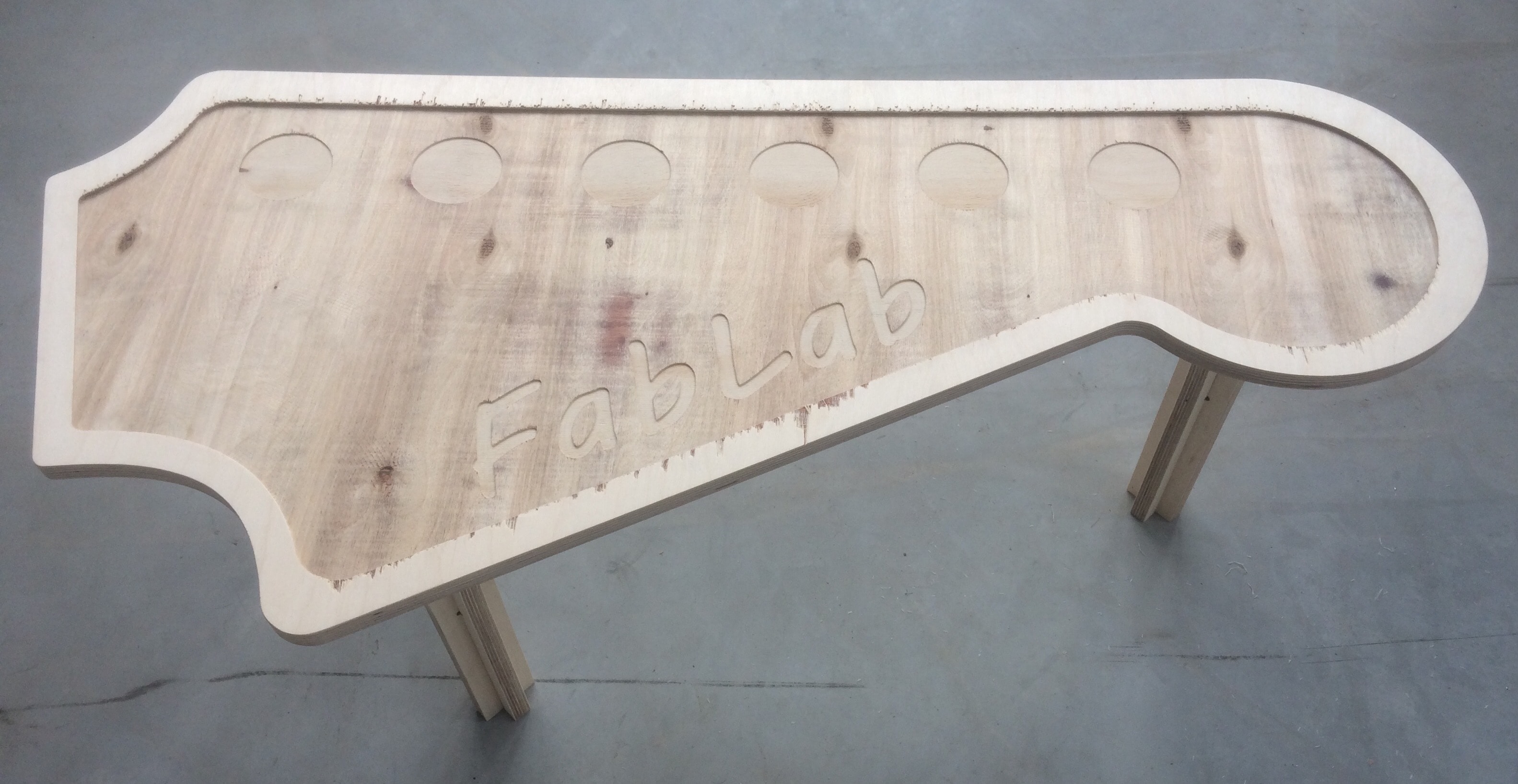
And this is what I get:
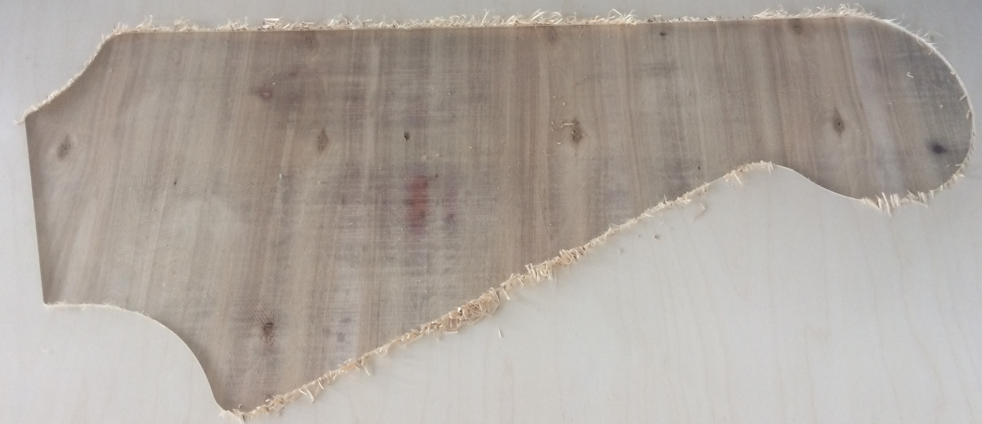
Looks very nice in my opinion)
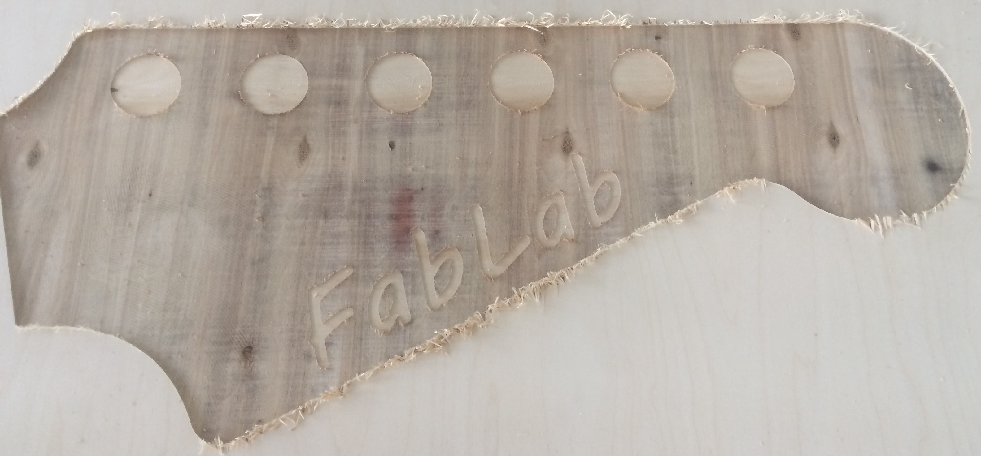
Now I can engrave the holes by one more millimeter. While waiting for the machine to finish the first job, I designed an inscription of FabLab which I will launch together with the holes:
This is the outcome:
Now its time to flip the wood sheet!
Honestly, it was a pain in the ass to align the holes on the old position. Luckily , I marked the holes inside, so it was easier to align!

I was really wondered, but we aligned it so well, that I did not have to position the X and Y axis again, it was exactly in the same position as before :p
And I launched the next job, which is the engraving of the joints
And finally, the last job of the outside cut and the legs.
Here is a short video of the process:
Problem:
I do not know if you noticed on the video, but there is actually a little mistake:
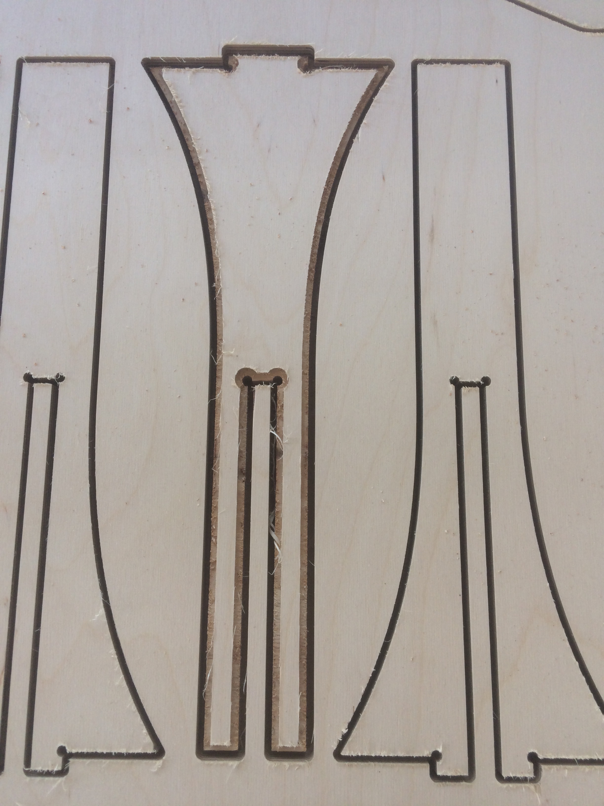
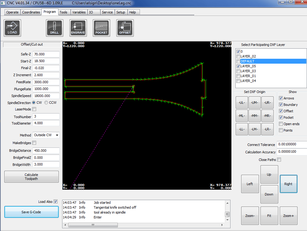
When the machine just started the job, it started with this leg. I noticed that something is wrong, and realized that this happened due to an error in the settings. I had to specify if it was an Inside Cut or an Outside Cut. In my case, it should be an outside cut, to keep the real dimensions, but I failed a bit) but better late than never... I realized my mistake on time, and stopped the job!
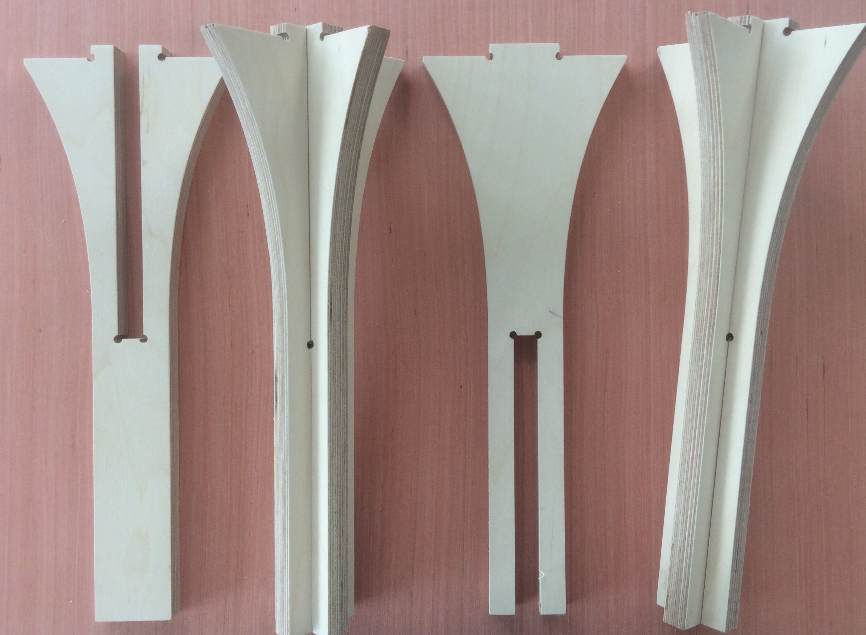
I fixed the settings, and continued the job. After it was done, I launched a new job only with one leg, the one that got ruined.
After all the pieces are done, I used the sandpaper to smooth the edges, and make everything look NICE

First, I joined the legs, and fortunately they fit pretty well!
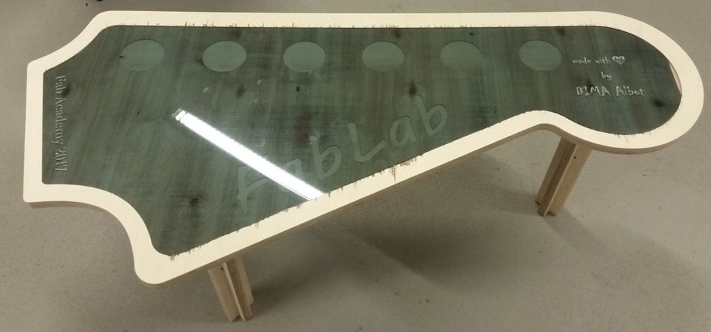
And then I joined the legs to the table. And HERE WE ARE!
I was so happy that everything was fitting together, and I do not have to do anything again...)))
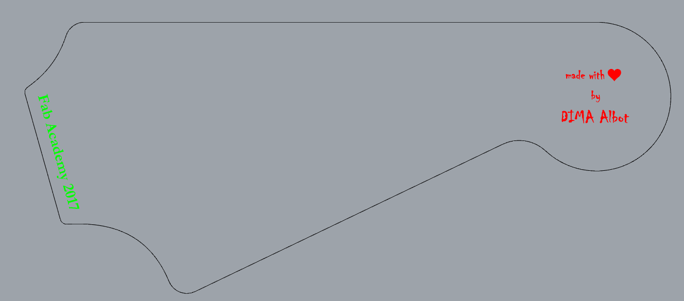
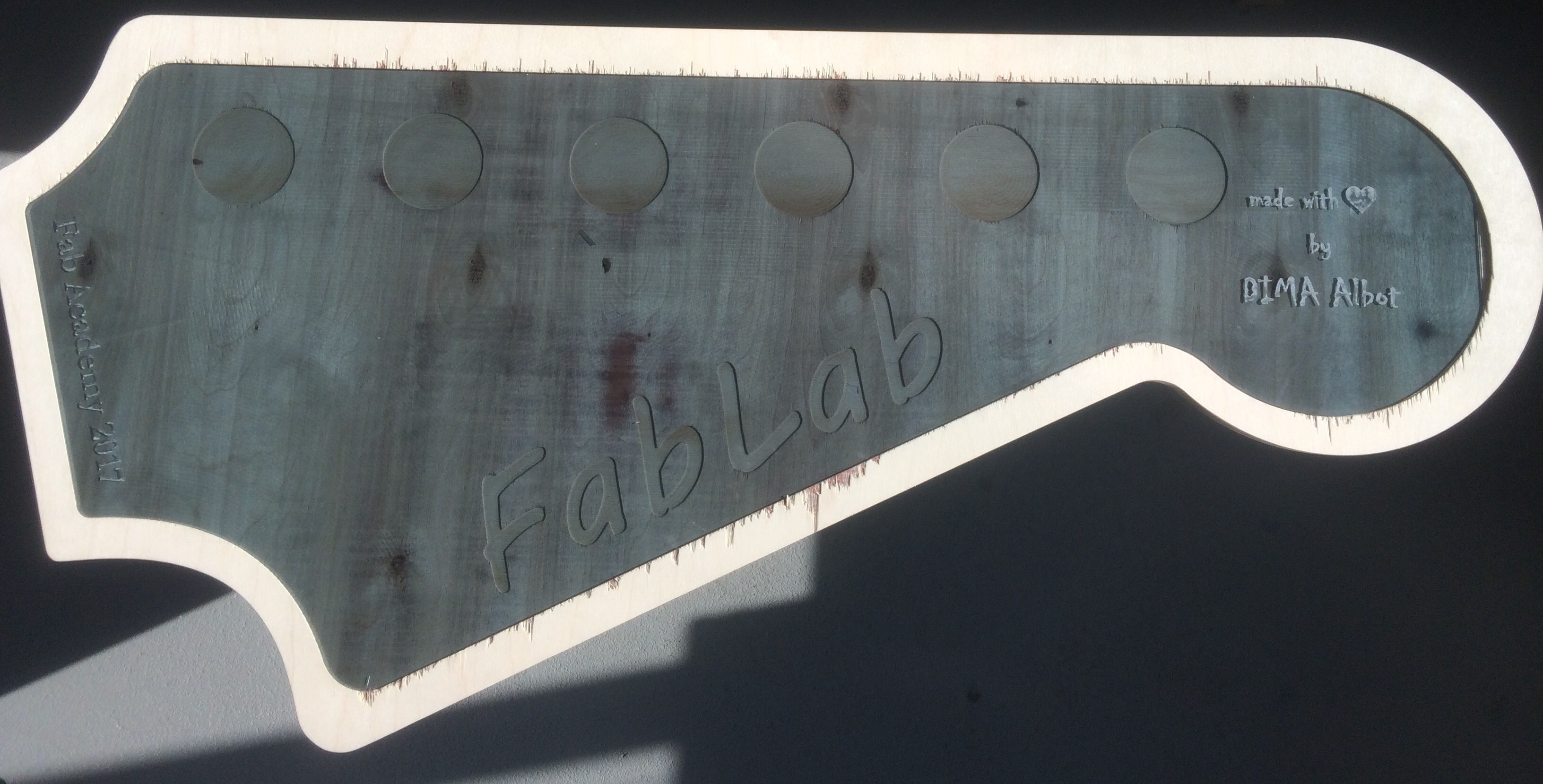
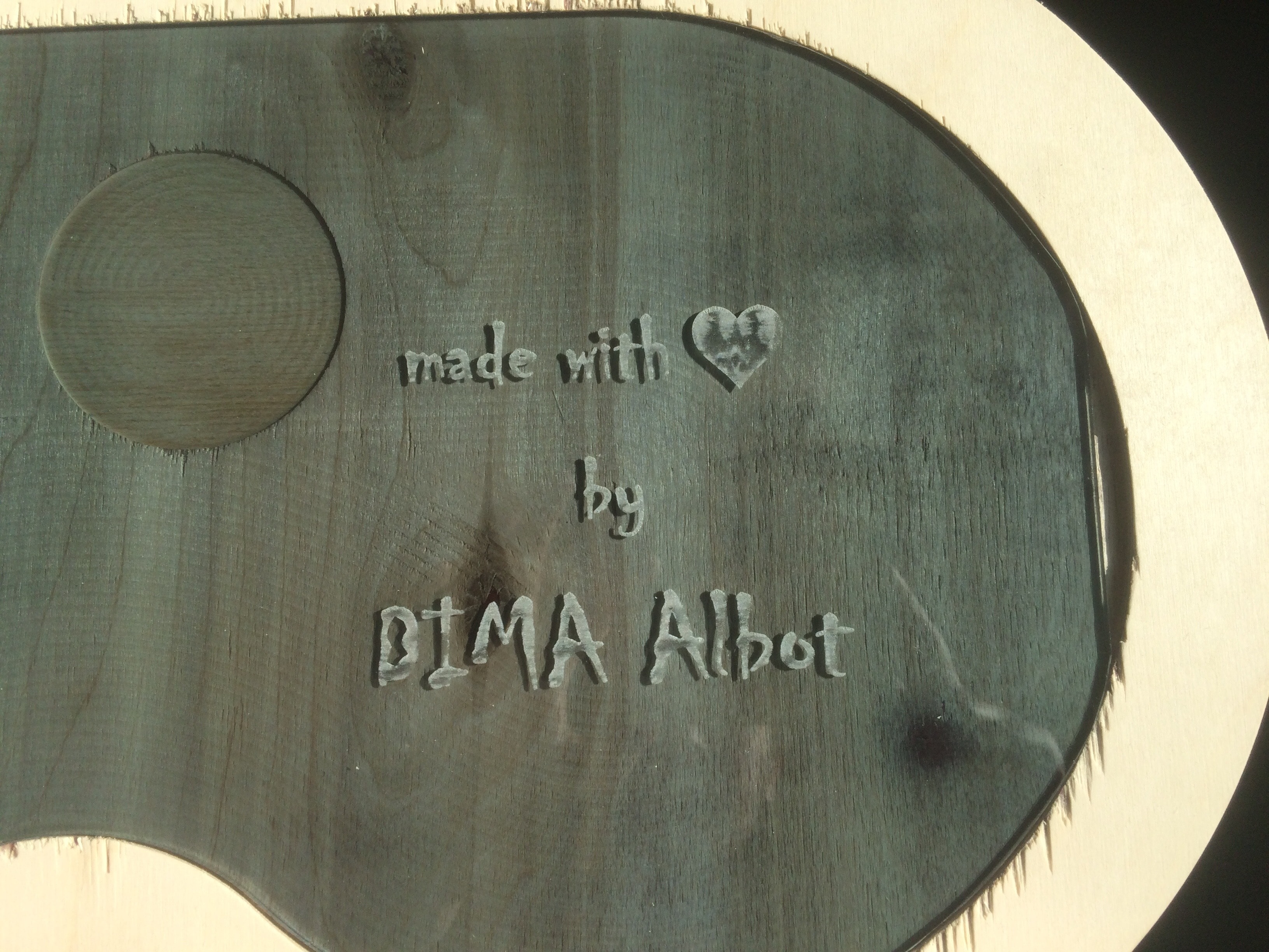
But then, I started to prepare the acrylic sheet to place it on the top. Because I already had the .dxf file, I just imported it in Rhino3D again, and added some inscriptions to engrave
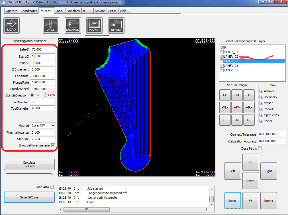
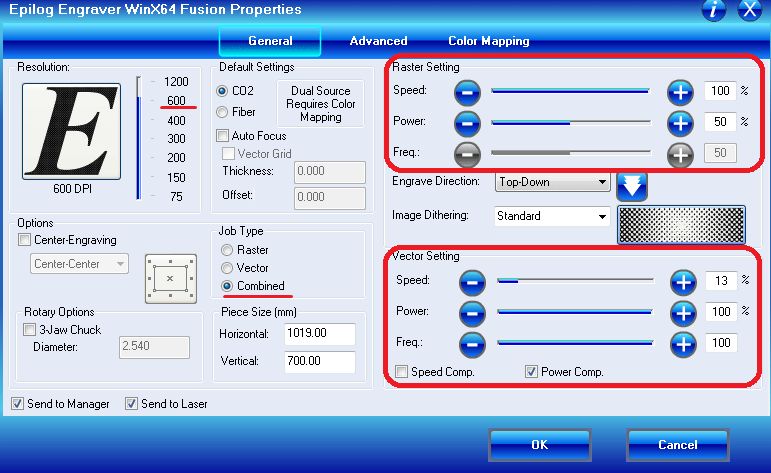
In my design, I had two different jobs, one is engraving, which I did first, and second one was the actual cut. I used color mapping to differentiate between two, and set also the order of the jobs. These are the settings I used:
My Final Design:
Download Files: