ELECTRONICS DESIGN
ASSIGNMENT
Re-draw the echo-hello-world board and add at least one button and LED (with current limiting resistor)
RE-DESIGN OF THE HELLO WORLD BOARD
Autodesk Eagle is used to design the echo-hello-world board from scratch.
Eagle is a PCB software that facilitates the creation of circuit designs by allowing the user to switch between two user interfaces - circuit, where components can be layed out and pcb traces, where the physical design can be set.
An attiny44 microcontroller is used. The Datasheet is checked for design considerations for the schematic.

Pinout of the attiny44 is taken into consideration before designing the board.
I decided to add a crystal, two LEDs and two buttons to the design.
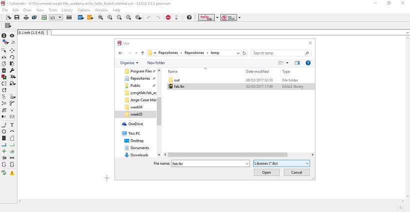
First, start by creating a project in the project management interface. I name my new project as 'fab_academy.echo_hello_board.

Next, create a new schematic design and open the file. Also, import the necessary component libraries. For the fab-academy, I imported the fab.lbr.
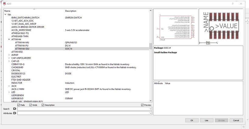
On the left tool pane, there is a tool to add components. I click on it to insert the Attiny44 microcontroller.
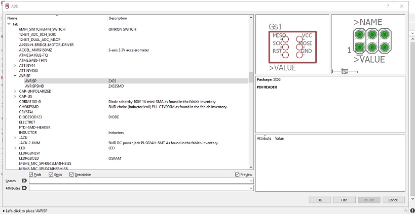
Proceed, by adding the AVRISP pins.
Add the rest of the components in the same manner.
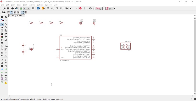
Label the pins in the microcontroller by clicking on the label icon on the right-hand tool pane. It will facilitate the drawing of connections.
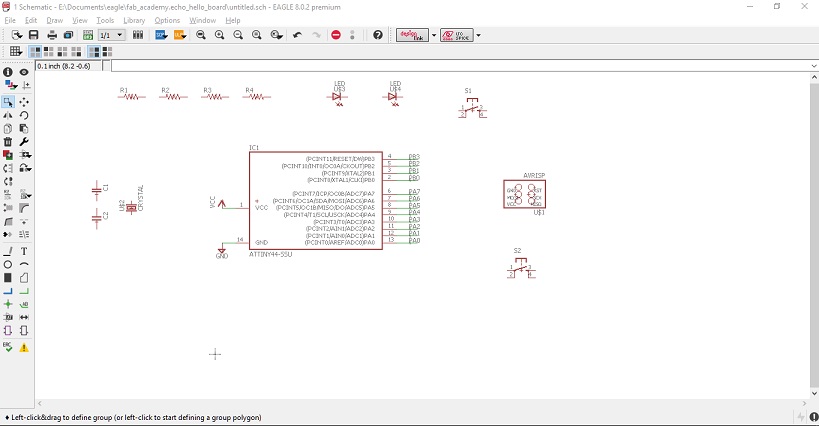
Start by making some connections, in the example below, I connect the crystal to two capacitors and the corresponding pins in the microcontroller.
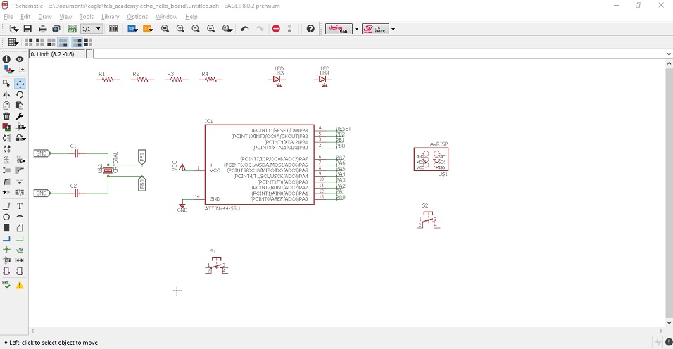
In the same way, connect the rest of the components. Double-check for the right components, in my case I noticed I put the wrong component for the AVRISP pins.
Three LEDs are added with correspoding current limiting resistor.

The value of the resistor is calculated by simple arithmetic:
$$E + V_{R_1} + V_{D} = 0 $$
$$-5 \mathrm{V} + V_{R_1} + 1.8\mathrm{V} = 0$$
$$V_{R_1} = 3.2\mathrm{V}$$
The LED, according to the Datasheet has a forward current of 40mA, therefore:
$$R_1 = \frac{3.2\mathrm{V}}{40*10^{-3}\mathrm{A}} = 80\Omega $$
Resistors of the value of 499 are used just to be safe.
Next, switch to the board view by clicking on the respective icon in the top toolbar.
This will bring a new user interface. It represents the physical location of the traces and components to be layed out.
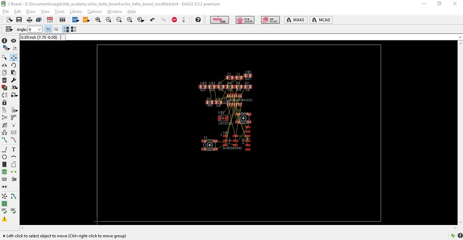
I proceed with sorting out the components; so the routing is easier.

Eagle has an auto-routing tool which is very useful in creating traces but not very precise. It is recommended to position and router manually critical components.
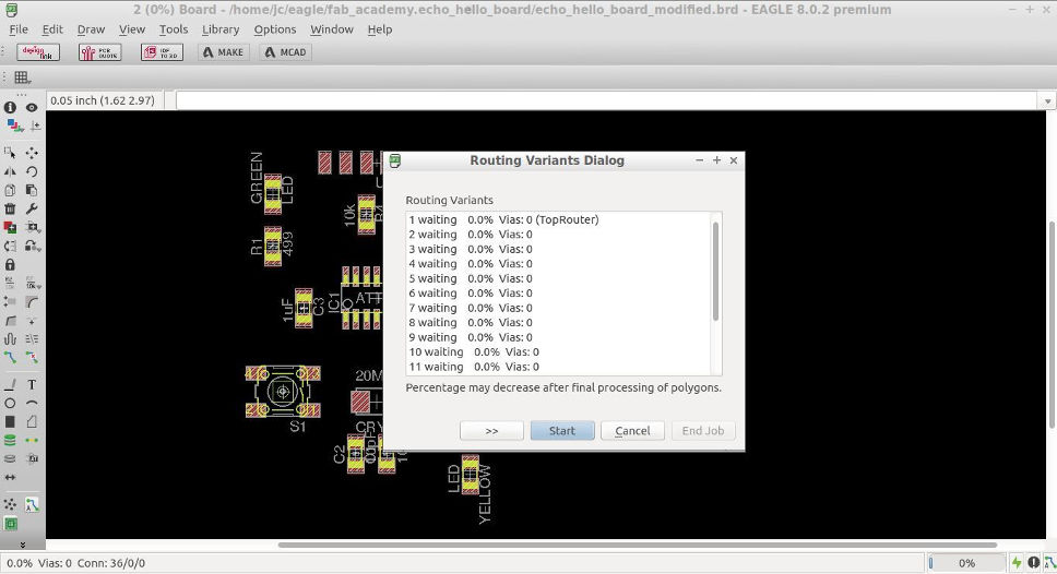
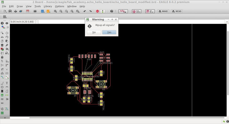
If the auto-routing is not satisfactory, eagle can erase all the traces at once. To do this, click on the rip-up icon in the toolbar and then, on the GO button in the action bar. A pop-up window will confirm the deletion of all traces.
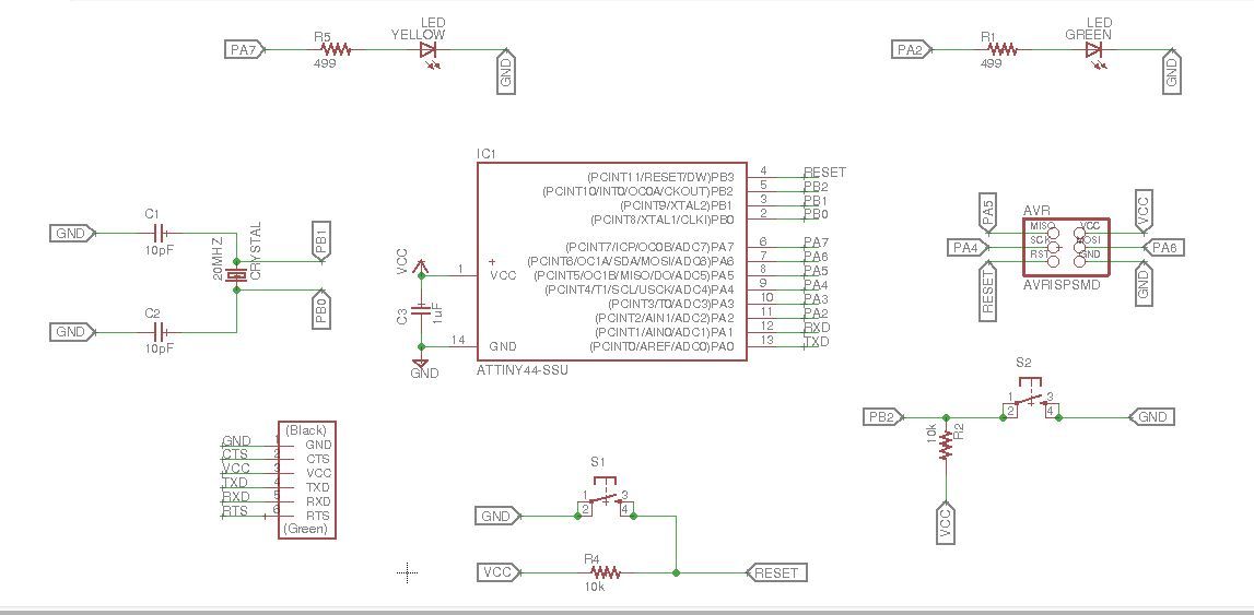
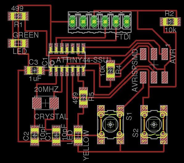
Finally I decided to route manually and change some components. the final design looked as follows:
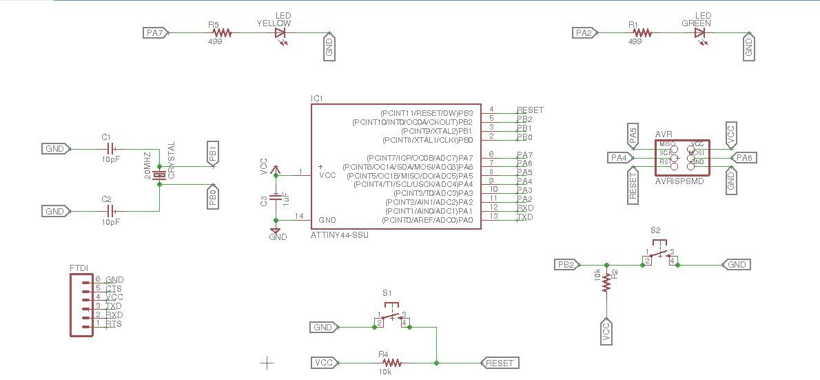
The updated schematic:
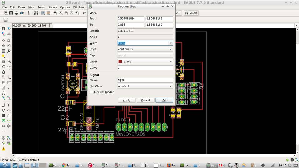
It is possible to set the width of all traces in Eagle. To do this, an ULP file must be run. To run a ULP program, go to the menu file/run-ULP.
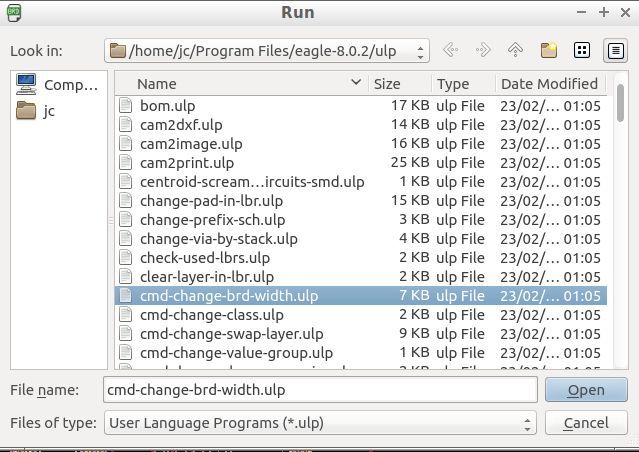
In the options box that will pop-up, click on the 'add-all' button and specify the new wire width.

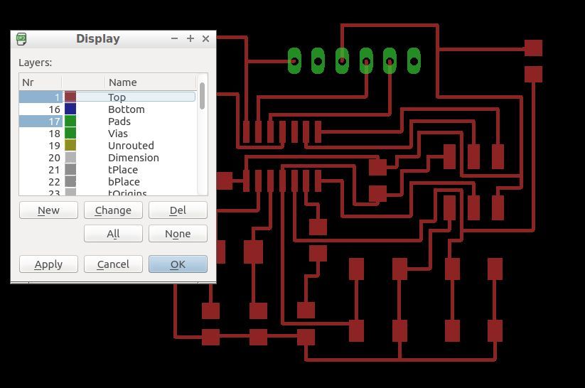
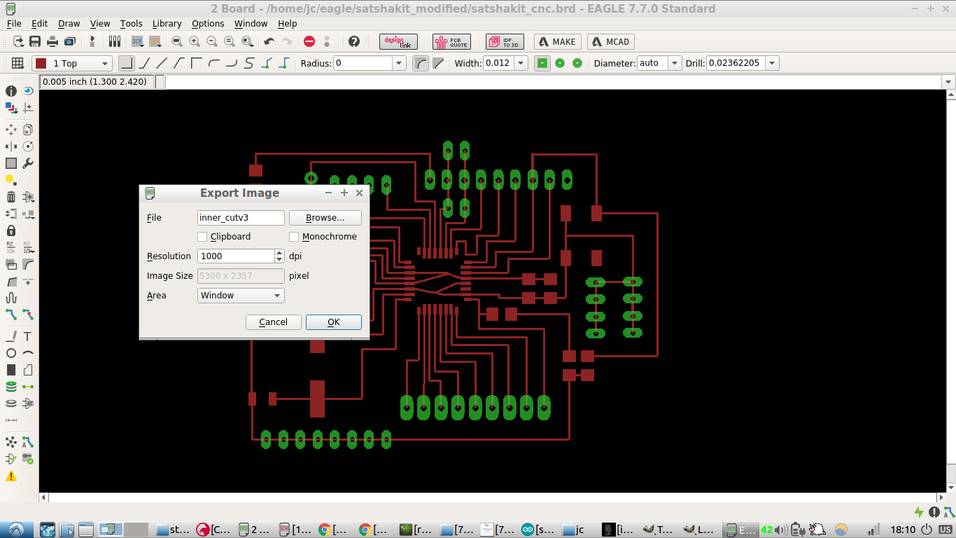
Once the design is finished, it is necessary to hide most layers, except the top and pads.
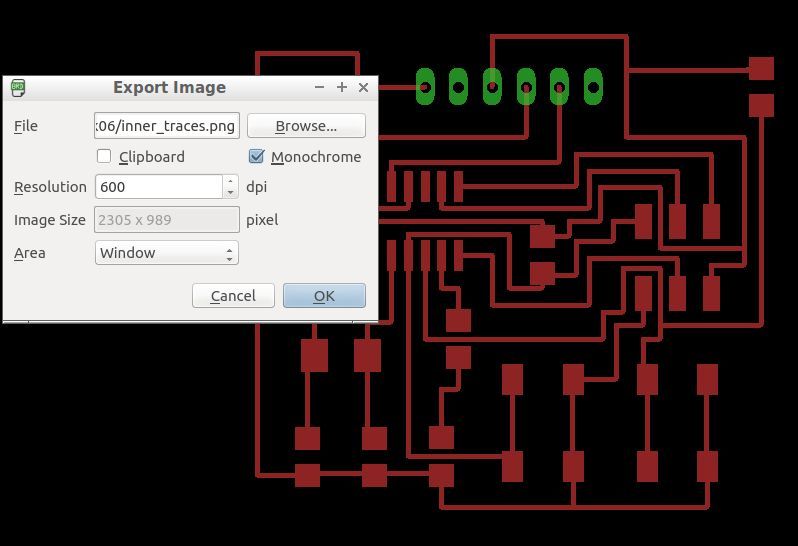
Now the file is ready to export as .png by going in the the menu toolbar to /file/export/image. Note the DPI and monochrome checkbox.
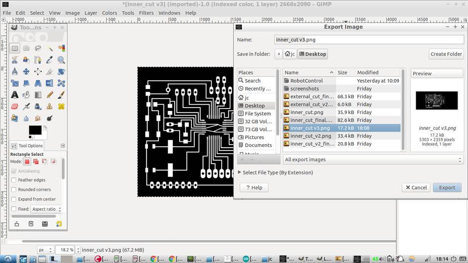
Next, open the file with an image editor and crop accordingly. This can be easily done with GIMP. To cut the outer traces, use the selection tool in GIMP to cut part of the image out.
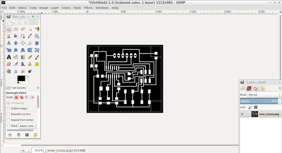
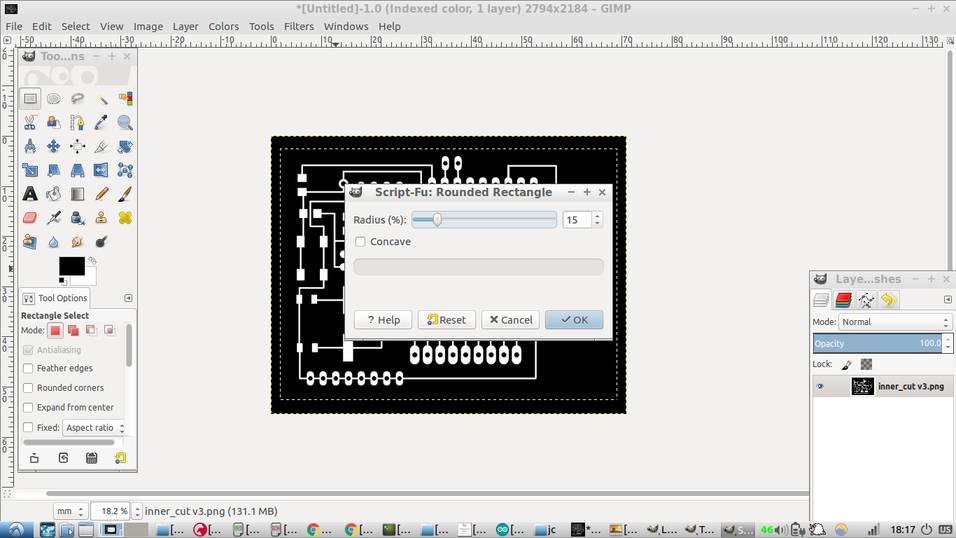
In order to avoid sharp edges in the outer trace, use the rounded rectangle tool in the menu toolbar in select/rounded_rectangle.

The final selection should look as follows:
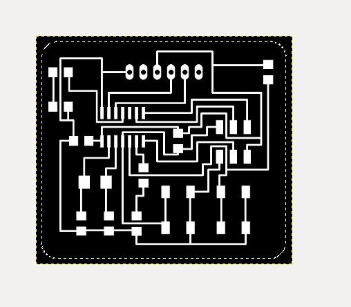
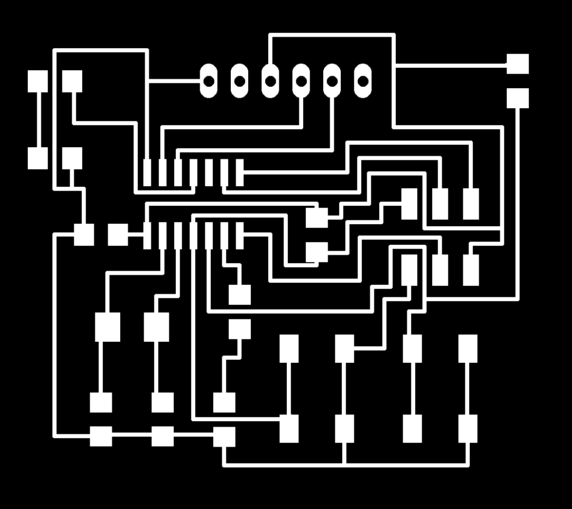
Crop the inner traces out and save. The two final files used in the milling are:

MILLING OF BOARD
The procedure is similar to how the hello-board was milled. The settings for the inner cut were:
speed: 4mm/s
Cut depth = 0mm
Tool diameter = 0.2mm
Number of offsets = 4
Offset overlap = 55%
Path error = 1.1 pixels
Image threshold = 0.5
As for the outer cut, the settings were:
speed: 0.5mm/s
cut depth = 2mm
tool diameter = 1mm
number of offsets = 1
offset overlap = 50%
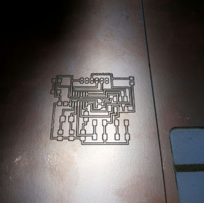
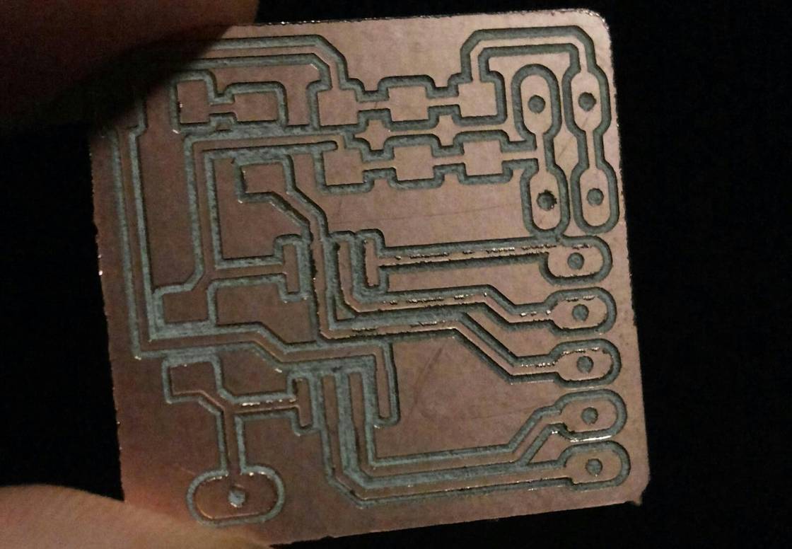
The board milled successfully with clear traces. Picture below shows the board traces right after the milling process finished.
SOLDERING
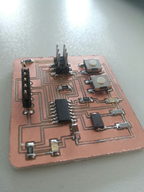
The board was soldered carefully and systematically. The microcontroller was soldered first and then the other components. The temperature of the solder iron was set around 330 degrees celsius and soldered joints were double-checked with a multimeter..
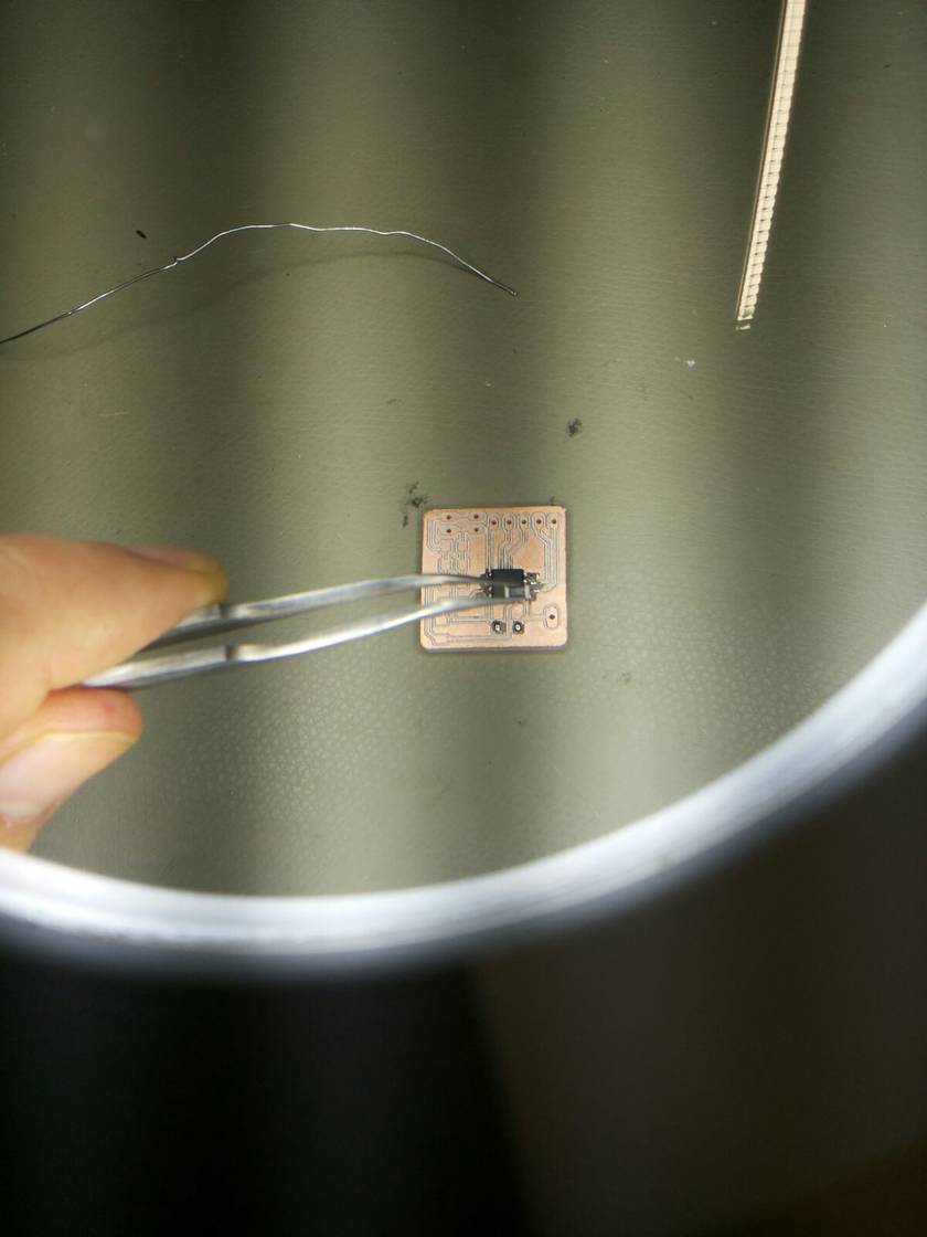
The final soldered board:
PROGRAMMING
I used again an arduino as ISP to program the board. The steps are similar to how the hello-board was programmed.
The steps are the following:
1. Connect the Arduino-Uno to your computer.
2. Select the port under tools.
3. Under file/examples open the 'arduino as isp' sketch.
4. Upload the sketch to the arduino.
5. Disconnect the arduino from the pc.
6. Connect the board with the arduino.
7. Double-check the connections.
8. Connect the arduino to the pc.
9. Select the right board, processor and frequency. In my case Attiny24/44/84, Attiny44, external 20Mhz.
10. Under tools in the Arduino IDE, select 'Arduino as ISP programmer'
11. Double-check all the settings.
12. Click on tools/burn_bootloader
13. Write your own program and upload using the arduino IDE, under sketch/upload_using_programmer
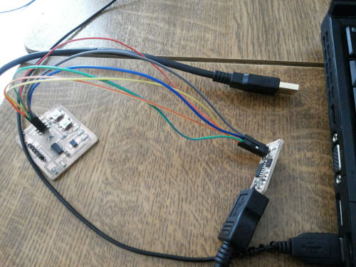
Illustrating the process, after uploading the arduino as ISP, the board was connected to the arduino-Uno using as follows:
HELLO BOARD	ARDUINO
-----------------------
RESET		PIN10
SCK		PIN13
MISO		PIN12
MOSI		PIN11

Next, the connections were doublechecked. It turns out one of the cables connected to the Arduino-uno was faulty.
Click on tools/burn_bootloader, the output IDE will show an output:
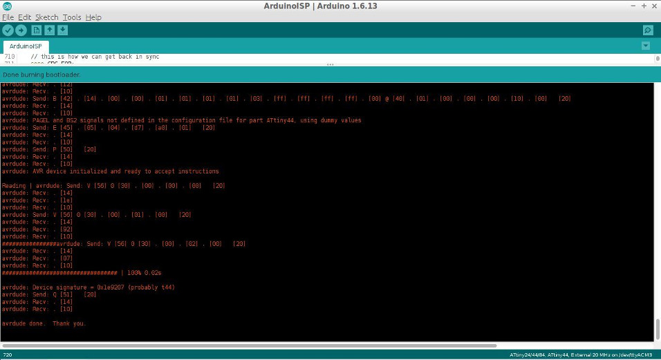
Burn-bootloader output:
avrdude: Version 6.3, compiled on Sep 12 2016 at 15:21:49
         Copyright (c) 2000-2005 Brian Dean, http://www.bdmicro.com/
         Copyright (c) 2007-2014 Joerg Wunsch

         System wide configuration file is "/home/jc/Downloads/1/arduino-1.6.13/hardware/tools/avr/etc/avrdude.conf"
         User configuration file is "/home/jc/.avrduderc"
         User configuration file does not exist or is not a regular file, skipping

         Using Port                    : /dev/ttyACM3
         Using Programmer              : stk500v1
         Overriding Baud Rate          : 19200
avrdude: Send: 0 [30]   [20]
avrdude: Send: 0 [30]   [20]
avrdude: Send: 0 [30]   [20]
avrdude: Recv: . [14]
avrdude: Recv: . [10]
         AVR Part                      : ATtiny44
         Chip Erase delay              : 4500 us
         PAGEL                         : P00
         BS2                           : P00
         RESET disposition             : possible i/o
         RETRY pulse                   : SCK
         serial program mode           : yes
         parallel program mode         : yes
         Timeout                       : 200
         StabDelay                     : 100
         CmdexeDelay                   : 25
         SyncLoops                     : 32
         ByteDelay                     : 0
         PollIndex                     : 3
         PollValue                     : 0x53
         Memory Detail                 :

                                  Block Poll               Page                       Polled
           Memory Type Mode Delay Size  Indx Paged  Size   Size #Pages MinW  MaxW   ReadBack
           ----------- ---- ----- ----- ---- ------ ------ ---- ------ ----- ----- ---------
           eeprom        65     6     4    0 no        256    4      0  4000  4500 0xff 0xff
                                  Block Poll               Page                       Polled
           Memory Type Mode Delay Size  Indx Paged  Size   Size #Pages MinW  MaxW   ReadBack
           ----------- ---- ----- ----- ---- ------ ------ ---- ------ ----- ----- ---------
           flash         65     6    32    0 yes      4096   64     64  4500  4500 0xff 0xff
                                  Block Poll               Page                       Polled
           Memory Type Mode Delay Size  Indx Paged  Size   Size #Pages MinW  MaxW   ReadBack
           ----------- ---- ----- ----- ---- ------ ------ ---- ------ ----- ----- ---------
           signature      0     0     0    0 no          3    0      0     0     0 0x00 0x00
                                  Block Poll               Page                       Polled
           Memory Type Mode Delay Size  Indx Paged  Size   Size #Pages MinW  MaxW   ReadBack
           ----------- ---- ----- ----- ---- ------ ------ ---- ------ ----- ----- ---------
           lock           0     0     0    0 no          1    0      0  9000  9000 0x00 0x00
                                  Block Poll               Page                       Polled
           Memory Type Mode Delay Size  Indx Paged  Size   Size #Pages MinW  MaxW   ReadBack
           ----------- ---- ----- ----- ---- ------ ------ ---- ------ ----- ----- ---------
           lfuse          0     0     0    0 no          1    0      0  9000  9000 0x00 0x00
                                  Block Poll               Page                       Polled
           Memory Type Mode Delay Size  Indx Paged  Size   Size #Pages MinW  MaxW   ReadBack
           ----------- ---- ----- ----- ---- ------ ------ ---- ------ ----- ----- ---------
           hfuse          0     0     0    0 no          1    0      0  9000  9000 0x00 0x00
                                  Block Poll               Page                       Polled
           Memory Type Mode Delay Size  Indx Paged  Size   Size #Pages MinW  MaxW   ReadBack
           ----------- ---- ----- ----- ---- ------ ------ ---- ------ ----- ----- ---------
           efuse          0     0     0    0 no          1    0      0  9000  9000 0x00 0x00
                                  Block Poll               Page                       Polled
           Memory Type Mode Delay Size  Indx Paged  Size   Size #Pages MinW  MaxW   ReadBack
           ----------- ---- ----- ----- ---- ------ ------ ---- ------ ----- ----- ---------
           calibration    0     0     0    0 no          1    0      0     0     0 0x00 0x00

         Programmer Type : STK500
         Description     : Atmel STK500 Version 1.x firmware
avrdude: Send: A [41] . [80]   [20]
avrdude: Recv: . [14]
avrdude: Recv: . [02]
avrdude: Recv: . [10]
avrdude: Send: A [41] . [81]   [20]
avrdude: Recv: . [14]
avrdude: Recv: . [01]
avrdude: Recv: . [10]
avrdude: Send: A [41] . [82]   [20]
avrdude: Recv: . [14]
avrdude: Recv: . [12]
avrdude: Recv: . [10]
avrdude: Send: A [41] . [98]   [20]
avrdude: Recv: . [14]
avrdude: Recv: . [00]
avrdude: Recv: . [10]
         Hardware Version: 2
         Firmware Version: 1.18
         Topcard         : Unknown
avrdude: Send: A [41] . [84]   [20]
avrdude: Recv: . [14]
avrdude: Recv: . [00]
avrdude: Recv: . [10]
avrdude: Send: A [41] . [85]   [20]
avrdude: Recv: . [14]
avrdude: Recv: . [00]
avrdude: Recv: . [10]
avrdude: Send: A [41] . [86]   [20]
avrdude: Recv: . [14]
avrdude: Recv: . [00]
avrdude: Recv: . [10]
avrdude: Send: A [41] . [87]   [20]
avrdude: Recv: . [14]
avrdude: Recv: . [00]
avrdude: Recv: . [10]
avrdude: Send: A [41] . [89]   [20]
avrdude: Recv: . [14]
avrdude: Recv: . [00]
avrdude: Recv: . [10]
         Vtarget         : 0.0 V
         Varef           : 0.0 V
         Oscillator      : Off
         SCK period      : 0.1 us

avrdude: Send: A [41] . [81]   [20]
avrdude: Recv: . [14]
avrdude: Recv: . [01]
avrdude: Recv: . [10]
avrdude: Send: A [41] . [82]   [20]
avrdude: Recv: . [14]
avrdude: Recv: . [12]
avrdude: Recv: . [10]
avrdude: Send: B [42] . [14] . [00] . [00] .
[01] . [01] . [01] . [01] . [03] . [ff] . [ff] . [ff] . [ff] . [00] @ [40] . [01] . [00] . [00] . [00] . [10] . [00]   [20]
avrdude: Recv: . [14]
avrdude: Recv: . [10]
avrdude: PAGEL and BS2 signals not defined in the configuration file for part ATtiny44, using dummy values
avrdude: Send: E [45] . [05] . [04] . [d7] . [a0] . [01]   [20]
avrdude: Recv: . [14]
avrdude: Recv: . [10]
avrdude: Send: P [50]   [20]
avrdude: Recv: . [14]
avrdude: Recv: . [10]
avrdude: AVR device initialized and ready to accept instructions

Reading | avrdude: Send: V [56] 0 [30] . [00] . [00] . [00]   [20]
avrdude: Recv: . [14]
avrdude: Recv: . [1e]
avrdude: Recv: . [10]
avrdude: Send: V [56] 0 [30] . [00] . [01] . [00]   [20]
avrdude: Recv: . [14]
avrdude: Recv: . [92]
avrdude: Recv: . [10]
################avrdude: Send: V [56] 0 [30] . [00] . [02] . [00]   [20]
avrdude: Recv: . [14]
avrdude: Recv: . [07]
avrdude: Recv: . [10]
################################## | 100% 0.02s

avrdude: Device signature = 0x1e9207 (probably t44)
avrdude: Send: Q [51]   [20]
avrdude: Recv: . [14]
avrdude: Recv: . [10]

avrdude done.  Thank you.
The operation was completed successfully. Next, I modified the basic blink program example to test the board. I uploaded the following program to my hello-world board:
/*
  Blink
  Turns on an LED on for one second, then off for one second, repeatedly.

  Most Arduinos have an on-board LED you can control. On the UNO, MEGA and ZERO
  it is attached to digital pin 13, on MKR1000 on pin 6. LED_BUILTIN takes care
  of use the correct LED pin whatever is the board used.
  If you want to know what pin the on-board LED is connected to on your Arduino model, check
  the Technical Specs of your board  at https://www.arduino.cc/en/Main/Products

  This example code is in the public domain.

  modified 8 May 2014
  by Scott Fitzgerald

  modified 2 Sep 2016
  by Arturo Guadalupi
*/


// the setup function runs once when you press reset or power the board
void setup() {
  // initialize digital pin LED_BUILTIN as an output.
  pinMode(PA7, OUTPUT);
  pinMode(PA2, OUTPUT);
}

// the loop function runs over and over again forever
void loop() {
  digitalWrite(PA7, HIGH);   // turn the LED on (HIGH is the voltage level)
  delay(1000);                       // wait for a second
  digitalWrite(PA2, HIGH);
  delay(1000);
  digitalWrite(PA7, LOW);    // turn the LED off by making the voltage LOW
  delay(1000);                      // wait for a second
  digitalWrite(PA2, LOW);
  delay(1000);
}
I upload the blink program to the hello-world board through the arduino IDE through Sketch/upload_using_programmer:
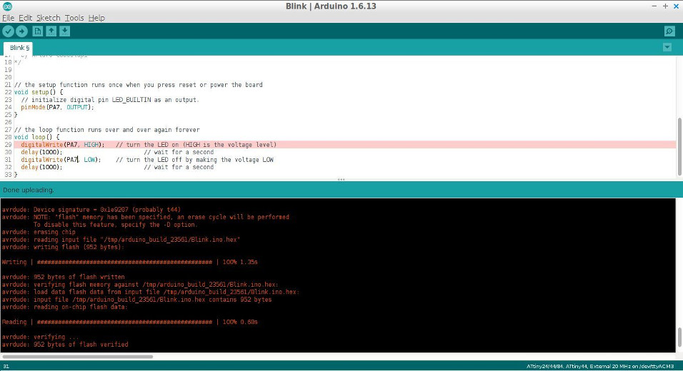
Upload output:
avrdude: Version 6.3, compiled on Sep 12 2016 at 15:21:49
         Copyright (c) 2000-2005 Brian Dean, http://www.bdmicro.com/
         Copyright (c) 2007-2014 Joerg Wunsch

         System wide configuration file is "/home/jc/Downloads/1/arduino-1.6.13/hardware/tools/avr/etc/avrdude.conf"
         User configuration file is "/home/jc/.avrduderc"
         User configuration file does not exist or is not a regular file, skipping

         Using Port                    : /dev/ttyACM3
         Using Programmer              : stk500v1
         Overriding Baud Rate          : 19200
avrdude: stk500_getsync() attempt 1 of 10: not in sync: resp=0x10
         AVR Part                      : ATtiny44
         Chip Erase delay              : 4500 us
         PAGEL                         : P00
         BS2                           : P00
         RESET disposition             : possible i/o
         RETRY pulse                   : SCK
         serial program mode           : yes
         parallel program mode         : yes
         Timeout                       : 200
         StabDelay                     : 100
         CmdexeDelay                   : 25
         SyncLoops                     : 32
         ByteDelay                     : 0
         PollIndex                     : 3
         PollValue                     : 0x53
         Memory Detail                 :

                                  Block Poll               Page                       Polled
           Memory Type Mode Delay Size  Indx Paged  Size   Size #Pages MinW  MaxW   ReadBack
           ----------- ---- ----- ----- ---- ------ ------ ---- ------ ----- ----- ---------
           eeprom        65     6     4    0 no        256    4      0  4000  4500 0xff 0xff
           flash         65     6    32    0 yes      4096   64     64  4500  4500 0xff 0xff
           signature      0     0     0    0 no          3    0      0     0     0 0x00 0x00
           lock           0     0     0    0 no          1    0      0  9000  9000 0x00 0x00
           lfuse          0     0     0    0 no          1    0      0  9000  9000 0x00 0x00
           hfuse          0     0     0    0 no          1    0      0  9000  9000 0x00 0x00
           efuse          0     0     0    0 no          1    0      0  9000  9000 0x00 0x00
           calibration    0     0     0    0 no          1    0      0     0     0 0x00 0x00

         Programmer Type : STK500
         Description     : Atmel STK500 Version 1.x firmware
         Hardware Version: 2
         Firmware Version: 1.18
         Topcard         : Unknown
         Vtarget         : 0.0 V
         Varef           : 0.0 V
         Oscillator      : Off
         SCK period      : 0.1 us

avrdude: AVR device initialized and ready to accept instructions

Reading | ################################################## | 100% 0.02s

avrdude: Device signature = 0x1e9207 (probably t44)
avrdude: NOTE: "flash" memory has been specified, an erase cycle will be performed
         To disable this feature, specify the -D option.
avrdude: erasing chip
avrdude: reading input file "/tmp/arduino_build_23561/Blink.ino.hex"
avrdude: writing flash (952 bytes):

Writing | ################################################## | 100% 1.35s

avrdude: 952 bytes of flash written
avrdude: verifying flash memory against /tmp/arduino_build_23561/Blink.ino.hex:
avrdude: load data flash data from input file /tmp/arduino_build_23561/Blink.ino.hex:
avrdude: input file /tmp/arduino_build_23561/Blink.ino.hex contains 952 bytes
avrdude: reading on-chip flash data:

Reading | ################################################## | 100% 0.68s

avrdude: verifying ...
avrdude: 952 bytes of flash verified

avrdude done.  Thank you.
PROGRAMMING OF PCB BOARD: FABISP
Now I proceed to program the board using FabISP.
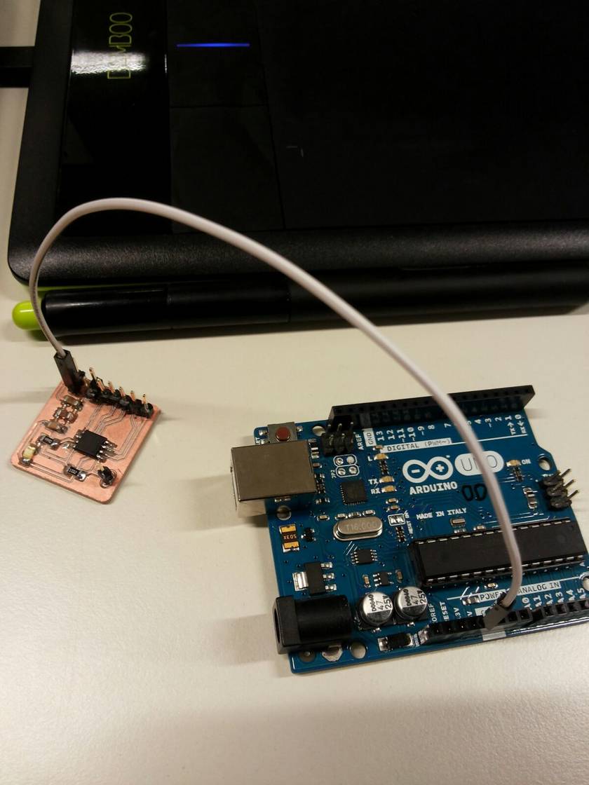
Firstly, the board is connected to the modified-hello world board connecting the respective MOSI, MISO, SCK, VCC, GND and RESET pins as shown below.

Connections are double-checked before uploading the code.
The following code is uploaded:
#include <avr/io.h>
#include <util/delay.h>
#define F_CPU20000UL

int main (void) {
    DDRA = 0xff;

    while(1) {
	PORTA |= (1 << PA7);
	_delay_ms(1000);
        PORTA |= (1 << PA2);
        _delay_ms(1000);
	PORTA ^= (1 << PA7);
	_delay_ms(1000);
        PORTA ^= (1 << PA2);
        _delay_ms(1000);
    }
   return 0;
}
Similarly, makefile is created:
PROJECT=test

SOURCES=$(PROJECT).c

MMCU=attiny44

F_CPU = 20000000


CFLAGS=-mmcu=$(MMCU) -Wall -Os -DF_CPU=$(F_CPU)


$(PROJECT).hex: $(PROJECT).out

	avr-objcopy -O ihex $(PROJECT).out $(PROJECT).c.hex;\

	avr-size --mcu=$(MMCU) --format=avr $(PROJECT).out


$(PROJECT).out: $(SOURCES)

	avr-gcc $(CFLAGS) -I./ -o $(PROJECT).out $(SOURCES)


program: $(PROJECT).hex

	avrdude -p t44 -P usb -c usbtiny -U flash:w:$(PROJECT).c.hex
In the command line, the following commands are executed: make and make program
These commands create the necessary hex and output files and upload the program to the board.
X220:~/Desktop/temp/blink$ make
avr-objcopy -O ihex test.out test.c.hex;\
avr-size --mcu=attiny44 --format=avr test.out
AVR Memory Usage
----------------
Device: attiny44

Program:     108 bytes (2.6% Full)
(.text + .data + .bootloader)

Data:          0 bytes (0.0% Full)
(.data + .bss + .noinit)


X220:~/Desktop/temp/blink$ make program
avr-objcopy -O ihex test.out test.c.hex;\
avr-size --mcu=attiny44 --format=avr test.out
AVR Memory Usage
----------------
Device: attiny44

Program:     108 bytes (3.2% Full)
(.text + .data + .bootloader)

Data:          0 bytes (0.0% Full)
(.data + .bss + .noinit)


avrdude -p t44 -P usb -c usbtiny -U flash:w:test.c.hex

avrdude: AVR device initialized and ready to accept instructions

Reading | ################################################## | 100% 0.00s

avrdude: Device signature = 0x1e9207 (probably t44)
avrdude: NOTE: "flash" memory has been specified, an erase cycle will be performed
         To disable this feature, specify the -D option.
avrdude: erasing chip
avrdude: reading input file "test.c.hex"
avrdude: input file test.c.hex auto detected as Intel Hex
avrdude: writing flash (108 bytes):

Writing | ################################################## | 100% 0.20s

avrdude: 108 bytes of flash written
avrdude: verifying flash memory against test.c.hex:
avrdude: load data flash data from input file test.c.hex:
avrdude: input file test.c.hex auto detected as Intel Hex
avrdude: input file test.c.hex contains 108 bytes
avrdude: reading on-chip flash data:

Reading | ################################################## | 100% 0.22s

avrdude: verifying ...
avrdude: 108 bytes of flash verified

avrdude: safemode: Fuses OK (E:FF, H:DF, L:FE)

avrdude done.  Thank you.
The blinking program worked as expected.
EXTRA: HELLO-WORLD BOARD
As a preparatory session, our fablab instructor let us mill and solder the hello-world board.
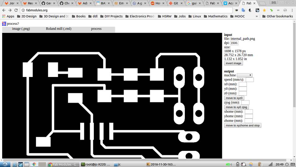
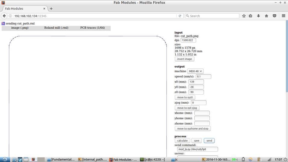
PCB Milling: Roland MDX-40A Settings:
- Use the FabModules portal to convert the .png image to .rml format
- Click on 'PCB traces' to trace the path for milling and set speed to 4mm/s.
- Select machine as MDX-40 and carefully move the machine tip by changing the values of 'x0, y0 and z0'. Make sure that 'zjog' stays at 0.
- Use a multimeter in 'Diode' mode to check that the tip of the CNC machine is touching the copper plate.
- Set parameters as follows:
Cut depth = 0mm
Tool diameter = 0.2mm
Number of offsets = 4
Offset overlap = 55%
Path error = 1.1 pixels
Image threshold = 0.5
Click on 'calculate' button to process the job.
- Once the machine has finished cutting the internal traces of the PCB. Locate the .png file for the 'cut path' and convert it to .rml format.
- Note that for cutting the copper plate, the speed must be set to 0.1
- As for the parameters for cutting use:
cut depth = 1.9m55m
tool diameter = 1mm
number of offsets = 1
offset overlap = 50%
- Click on 'calculate' and process the job. Image below illustrates the milling process.


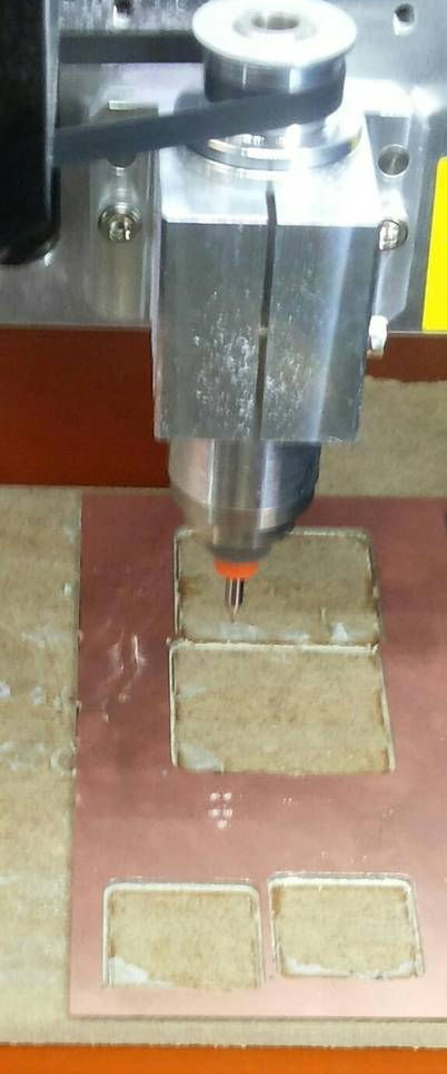
The final result
SOLDERING
- Prepare soldering station and set temperature.
- Solder components carefully.
- Check that there are not any bridges with a multimeter.
- The finished soldered piece:
- Create a new project on Eagle's control panel.
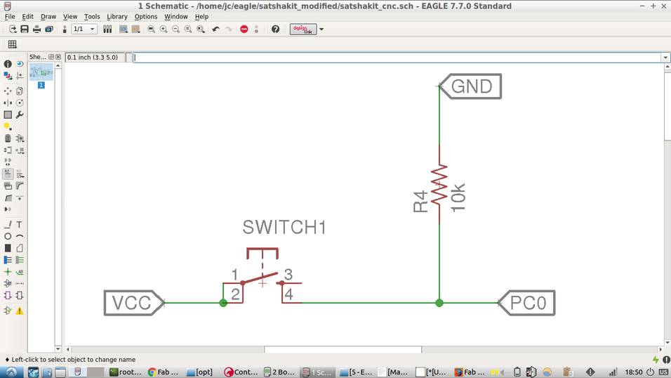
- Add a switch button.
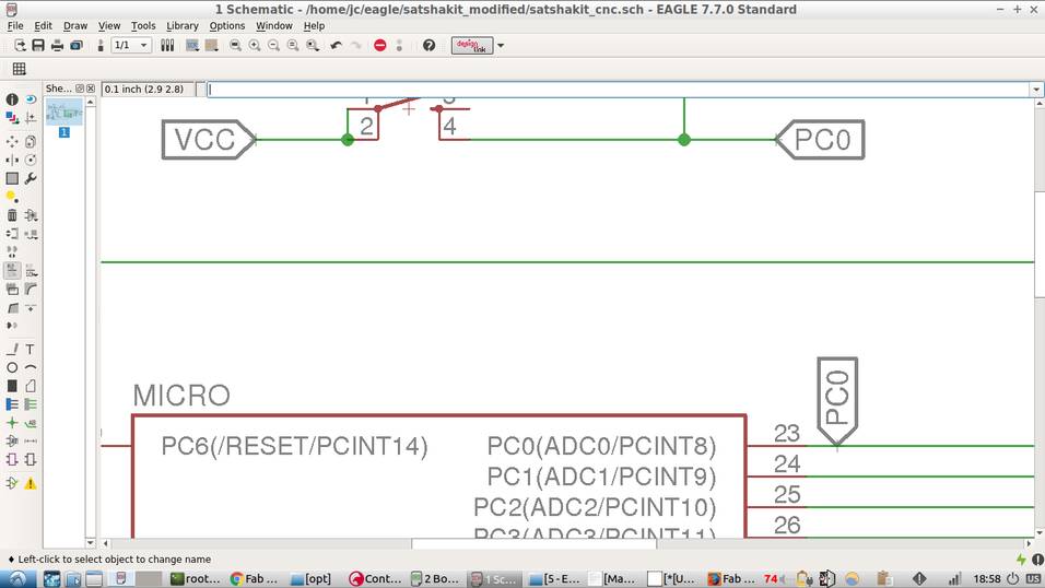
- Connect one terminal of the switch to pin PC0 using a label.
- Add some wire to the other terminal and add a label, name the label VCC.
- Copy the 10k resistor or add a new one and connect it as a pull-down resistor to the switch and ground. The pull down resistor will make the input LOW whenever the switch remains unpressed.
- Add the label PC0 in the respective microcontroller pin.
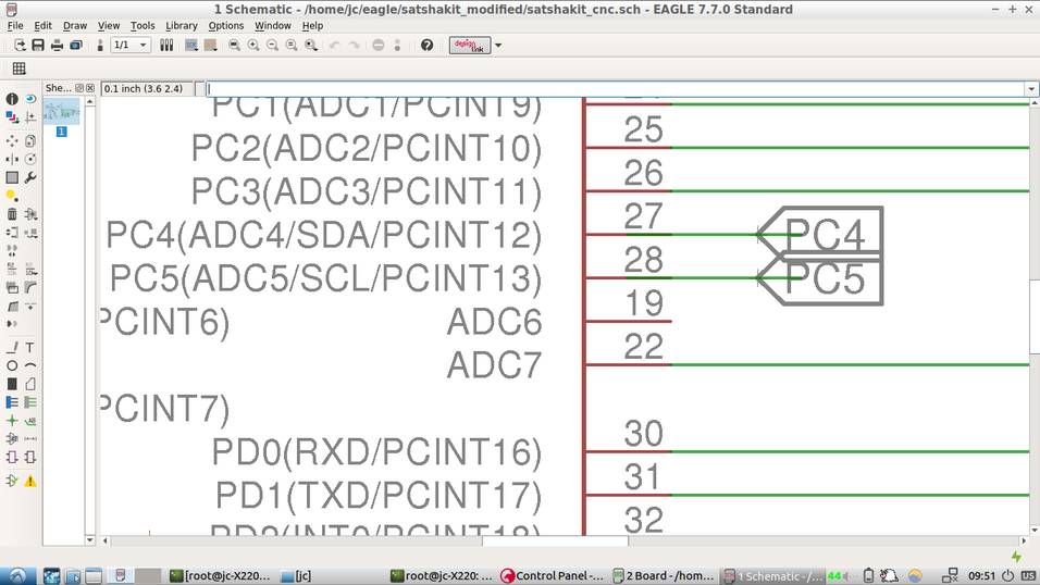
- Now proceed to add a label for the SDA and SCL pins.
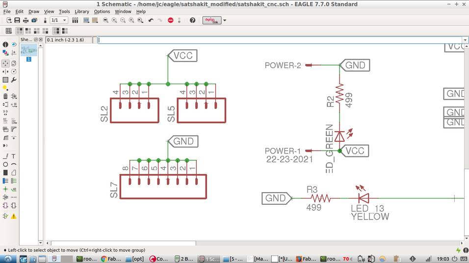
- Add to the schematics, two 4 pin-headers with respective labels.
- Add 8 pin-headers for VCC and 8 pin-headers for GND. Connect them by using a label.
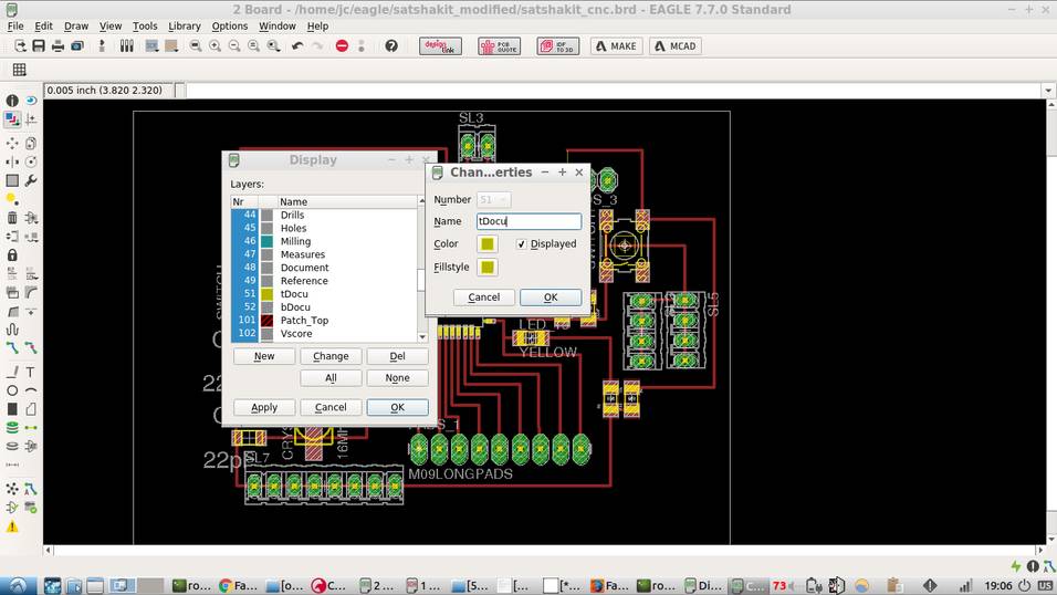
- Now get ready to route the board. Switch to board view.
- Go to display layers and change tDocu to yellow. This step will allow for better visibility of traces.
- Route the board carefully. This is the most time-consuming step. In my case, there was the need to rotate and re-arrange components. Note that no 0-ohm resistor was used.
- Make sure the routing width is 0.012.
- Traces were very difficult and time-consuming to route. A crucial step is to place components logically.
- Soldering microcontroller joints require practice. I found the smallest soldering tip did not work for me; I used a standard-sized one.
- Soldering the AVR pins and crystal requires patience and practice too.
- When programming, I spent over 2 hours debugging. It turned out that one of the cables connecting the arduino and my hello-board was faulty
- Improved my soldering skills.
- Became more comfortable using Eagle, and patient too while routing the traces!.
- Improved my familiarity with the Roland CNC machine.
- Learned how to use an arduino as an ISP.
- Used MATHJAX for this page's current limiting resistor calculations.

PROGRAMMING OF PCB BOARD: ARDUINO AS ISP
The following steps were taken to set up the board using an Arduino Uno as an ISP programmer
 1 - connect the arduino uno to the pc
 2 - select the right port and the arduino uno board under tools
 3 - under file->examples find and open the arduino as isp sketch
 4 - upload the sketch to the arduino
 5 - disconnect the arduino from the pc
 6 - connect the hello board with the arduino (check the connection schema)
 7 - triple check the connections
 8 - connect the arduino to the pc
 9 - select the right board/processor/frequency -> attiny25/45/85, attiny45, internal 8mhz
 10 - under tools select the arduino as isp programmer
 11 - double check all the paramters
 12 - click to tools-> burn bootloader
 13 - write your own program
 14 - to program the board do sketch->upload using programmer
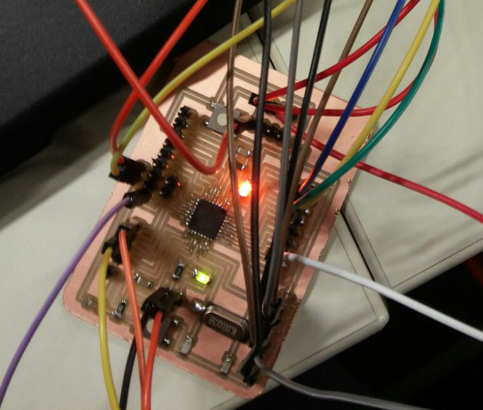
Connect the pins correctly to the arduino board as follows:

Make sure you connect VCC to the correct pin. In the picture below, I used a white coloured cable for VCC
Once all pins are connected correctly, connect arduino via the USB port to upload a program using the programmer.

Load the example 'blink' program and change LED_BUILTIN value to 2.
/*
  Blink
  Turns on an LED on for one second, then off for one second, repeatedly.

  Most Arduinos have an on-board LED you can control. On the UNO, MEGA and ZERO
  it is attached to digital pin 13, on MKR1000 on pin 6. LED_BUILTIN takes care
  of use the correct LED pin whatever is the board used.
  If you want to know what pin the on-board LED is connected to on your Arduino model, check
  the Technical Specs of your board  at https://www.arduino.cc/en/Main/Products

  This example code is in the public domain.

  modified 8 May 2014
  by Scott Fitzgerald

  modified 2 Sep 2016
  by Arturo Guadalupi
*/


// the setup function runs once when you press reset or power the board
void setup() {
  // initialize digital pin LED_BUILTIN as an output.
  pinMode(LED_BUILTIN, OUTPUT);
}

// the loop function runs over and over again forever
void loop() {
  digitalWrite(LED_BUILTIN, HIGH);   // turn the LED on (HIGH is the voltage level)
  delay(1000);                       // wait for a second
  digitalWrite(LED_BUILTIN, LOW);    // turn the LED off by making the voltage LOW
  delay(1000);                       // wait for a second
}
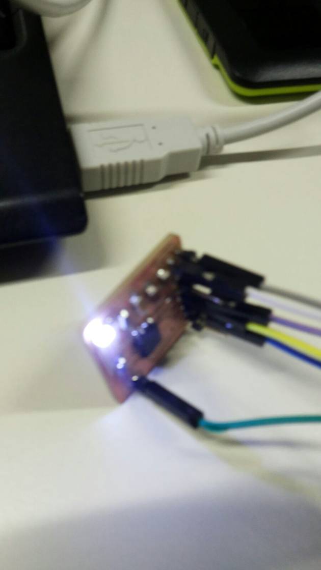
Press upload and if the board is working, it will blink.
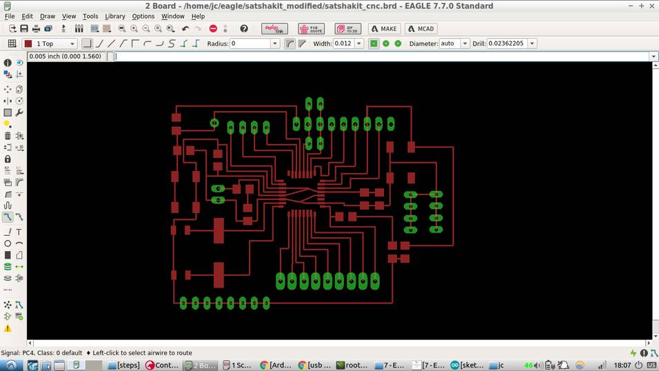
EXTRA: MODIFYING THE SATSHAKIT
For this project I will use the cnc version of the Satshakit Board, a design by Daniel Ingrassia, our main mentor here at the Fab-Lab Kamp-Lintfort. It provides equally capable funcionality as an Arduino-UNO and uses an ATmega328p microcontroller.


MILLING OF MODIFIED-SATSHAKIT
Roland MDX-40A was used to mill this piece.
Export board as monochrome image.
Modify exported file with Gimp or preferred image editor and save two files, one for the inner engraving and another for the external cut.
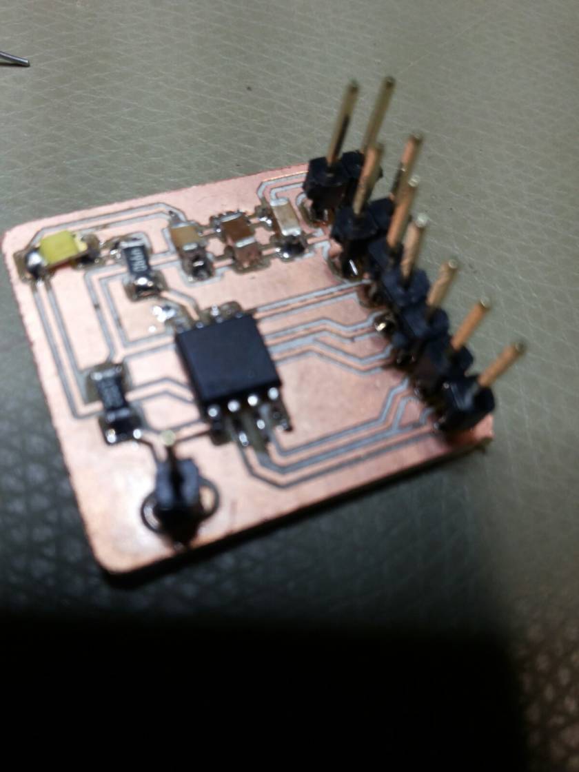
Final routed board, looks as follows:
Resulting images should look as follows:


The parameters for the inner-cut were:
Cut depth = 0mm
Tool diameter = 0.2mm
Number of offsets = 4
Offset overlap = 55%
Path error = 1.1 pixels
Image threshold = 0.5
Milling path is calculated, there seems to be no errors.

The parameters for the external-cut were:
cut depth = 1.9mm
tool diameter = 1mm
number of offsets = 1
offset overlap = 50%
The board was soldered and programmed as explained before. Here a picture of the final board:
SOME CONSIDERATIONS
How to copy a schematic in eagle: click group button, select components. click on menu, select copy.
ROUTER TRACES: 0.012
PROBLEMS AND CHALLENGES
LESSONS LEARNED
FILES
Modified echo hello world inner traces PNG
Modified echo hello world inner traces PNG
Hello board c code and makefile
Modified Satshakit External Cut
Modified Satshakit Eagle Schematic
Modified Satshakit Eagle Board