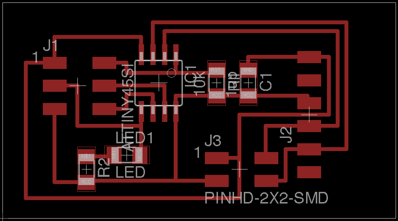
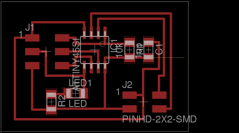
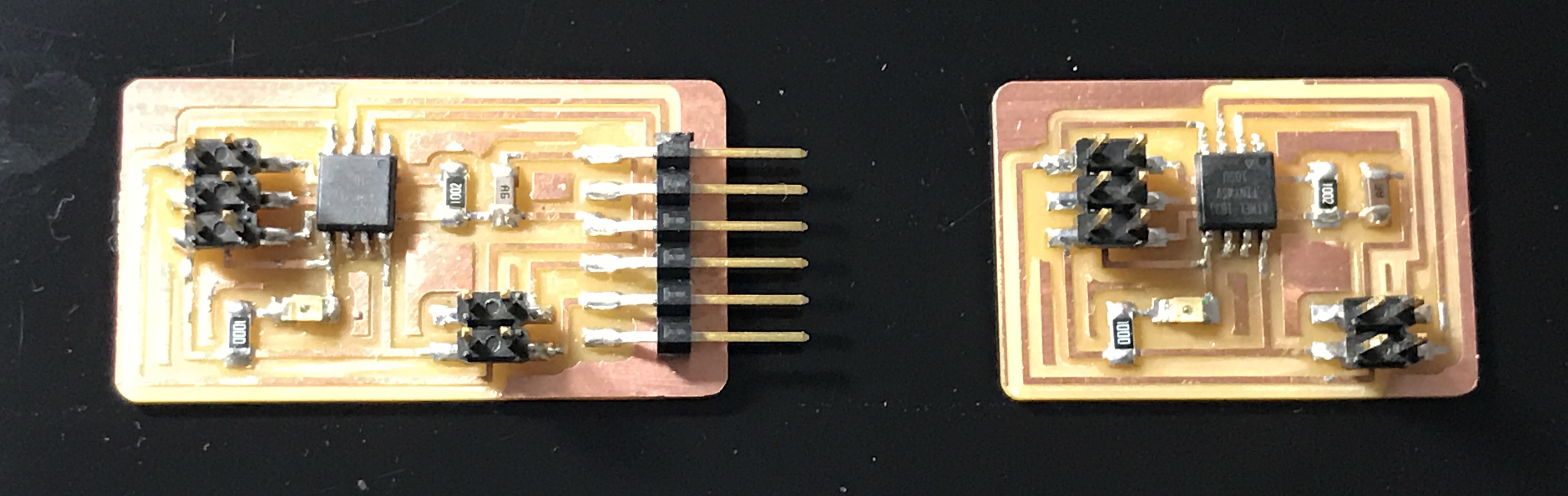
download .sch .brd top.png outline.png I made one Bridge board and two node board. I made mistake soldering ATtiny45 wrong direction. I was told by Instructor that circle mark on ATtiny45 is RESET. Then I took off the IC and re-solder in right direction. Even though I could not write program to one node. I could not find why it did not work. So I made one more node again.
Program
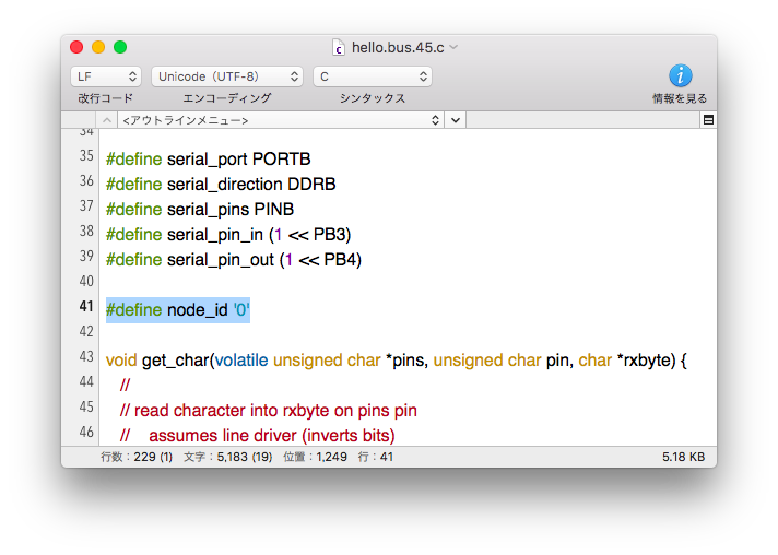
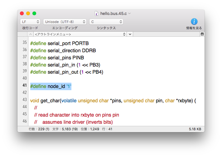
I use hello.bus.45.c and makefile from class page.
"node_id" has to be change '0' as bridge to '1','2'... as node.
On terminal as follow week08
$ cd Desktop/week15/
$ make -f hello.bus.45.make
$ sudo make -f hello.bus.45.make program-usbtiny
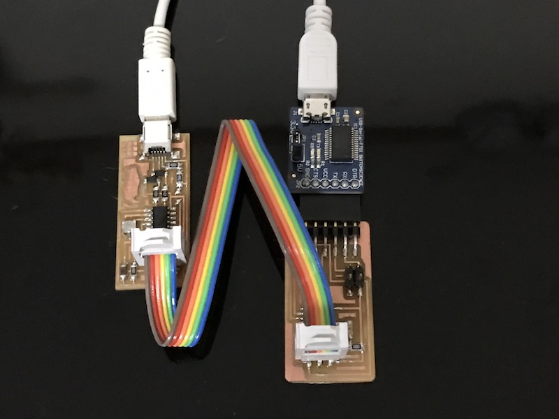
"node_id '0' "program to bridge board. Power is from USB-Serial FTDI.
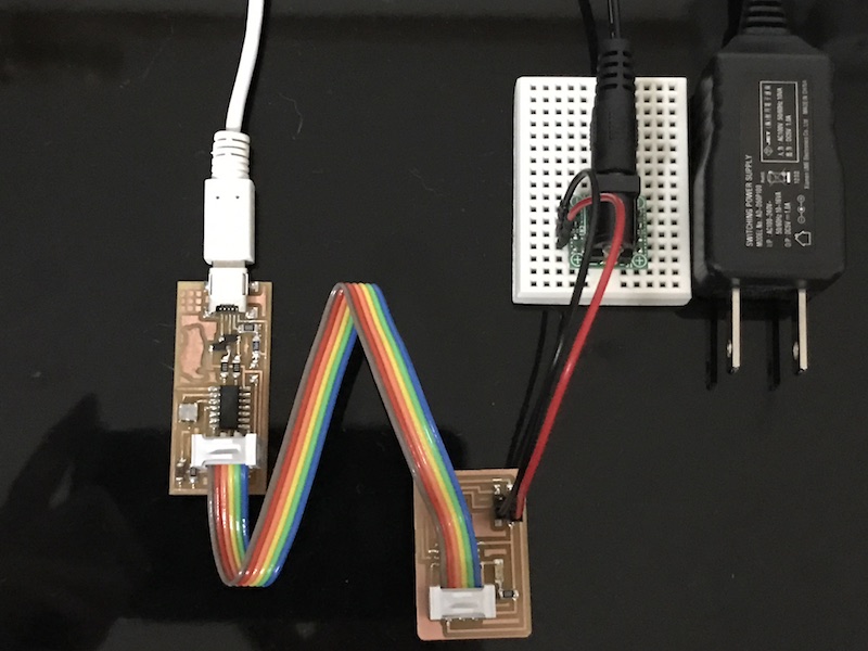
"node_id '1' "program to node board. Power is from 5V DC adapter.
This is the connection Bridge to nodes.
Download term.py from week08 class page.
Get serial port information
$ ls /dev | grep usb
cu.usbserial-AI02RJUC
tty.usbserial-AI02RJUC
or
$ ls /dev/tty.*
/dev/tty.Bluetooth-Incoming-Port /dev/tty.usbserial-AI02RJUC
Run term.py
$ python term.py /dev/tty.usbserial-AI02RJUC 9600
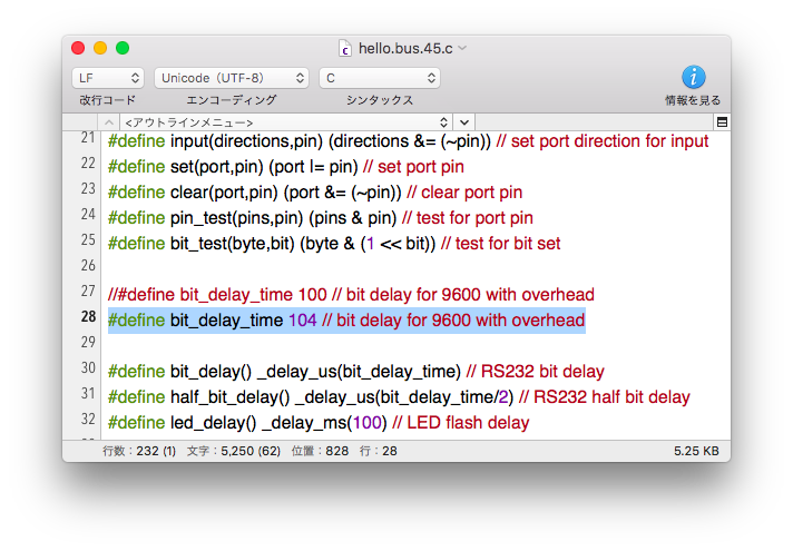
Unfortunately I could not get response like "node 0" on screen. Then I saw FabAcademy Graduate page who had similar problem. I changed "bit_delay_time" 100 to 104 as below. I re-compiled all boards.
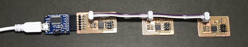
Now I get correct wired network connection.
Arduino Serial Monitor I used Arduino Serial Monitor instead of term.py . Sketch is not needed.
Example: Type "0" and send (=press enter), then LED on bridge(=node 0) blink and "node 0" is appeared on Monitor
RF WiFi
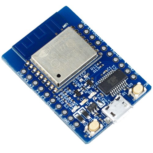
ESP8266 ESP-WROOM-02 board is used.
I used this board as Arduino board befoer, so I need to re-write firmware for AT command network connecting.
Firmware Download " V1.3.0.2 AT Firmware.bin.zip "from ESP8266_AT-Command_firmware .
Unzip and rename V1.3.0.2 AT Firmware.bin to "ATFirmware.bin" with no space in the name.
Flash Writer To re-wright firmware, Flash writer is needed. Git clone from https://github.com/espressif/esptool and unzip it to get "esptool-master" .
$ cd esptool-master
$ python setup.py install
Re-write firmware
$ ls /dev | grep usb
cu.usbserial-DN01ELLJ
tty.usbserial-DN01ELLJ
Firmware Installed
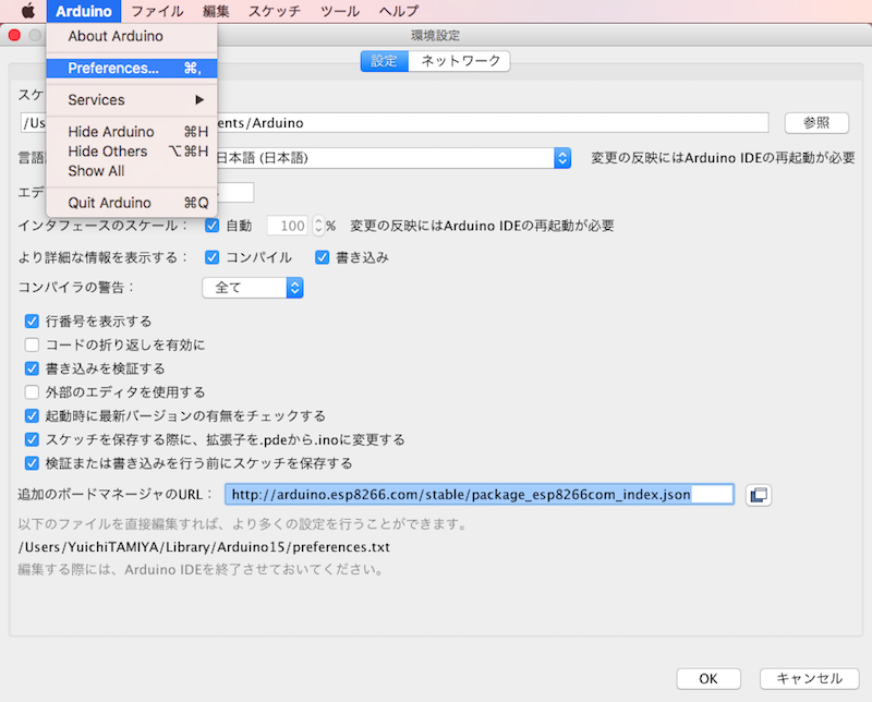
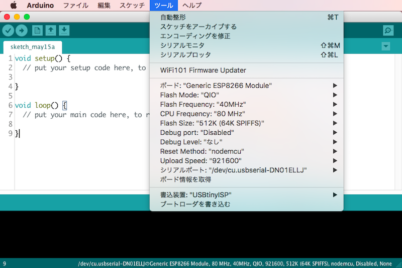
Arduino IDE setting To use Arduino Serial Monitor, copy this URL below
" http://arduino.esp8266.com/stable/package_esp8266com_index.json "
Open Arduino IDE -> Preference ->Paste the URL to "Additional Boards Manager URLs".
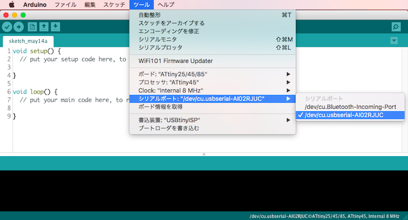
From Tool, set board like below
AT Command
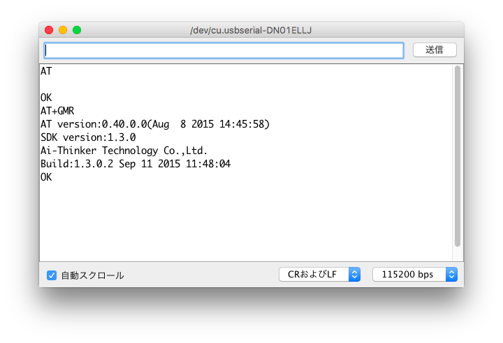
General
AT
get version
AT+GMR
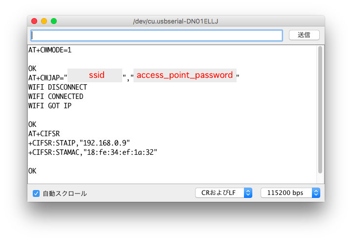
Join Access Point
station mode
AT+CWMODE=1
join access point
AT+CWJAP="access_point_ssid","access_point_password"
list IP address
AT+CIFSR
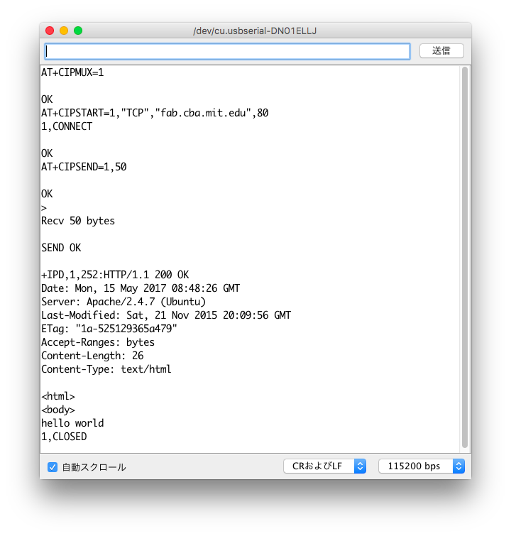
TCP client: get Web page
multiple connection mode for TCP
AT+CIPMUX=1
open TCP connection 1 to fab.cba.mit.edu port 80
AT+CIPSTART=1,"TCP","fab.cba.mit.edu",80
send Web page request on connection 1, with character count
AT+CIPSEND=1,50
GET /test.html HTTP/1.1
HOST: fab.cba.mit.edu
"press_return_once"
close connection 1
AT+CIPCLOSE=1
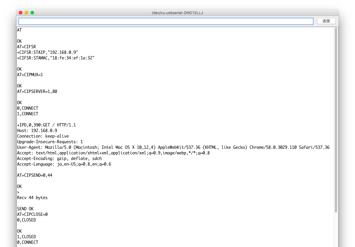
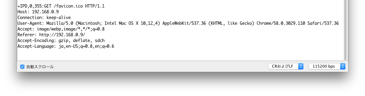
TCP server: send Web page
list IP address
AT+CIFSR
multiple connection mode
AT+CIPMUX=1
start TCP server, on port 80
AT+CIPSERVER=1,80
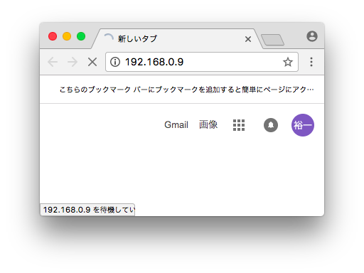
Open browser, then copy and paste IP address from AT+CIFSR
send Web page reply on connection 0, with character count
AT+CIPSEND=0,44
HTTP/1.1 200 OK
"press_return_once"
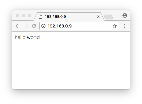
<html><body>hello world