Week10: Output Devices
Assignment
add an output device to a microcontroller board you've designed and program it to do something
Output Device
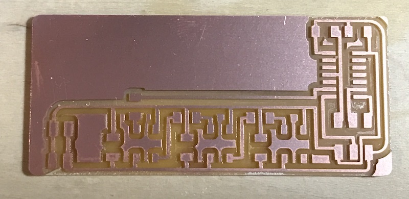
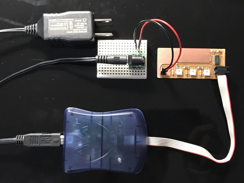
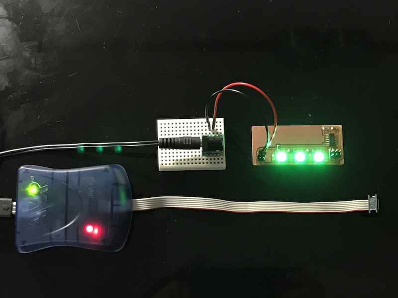
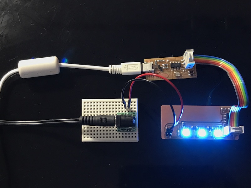
I made my_led board with full color LED "WS2812B".
R1:
Resistance
10k [ohm](1002)
x 1
C1:
Capacitor
1u [F]
x 1
IC1:
Attiny 44
x 1
JP1 ISP:
Pin header
2x3
x 1
JP2 power:
Pin header
2X2
x 1
LED:
WS2812B
x 3
R2,R3,R4:
Resistance
100 [ohm](101)
x 3
C2,C3,C4:
Capacitor
0.1u [F]
x 3
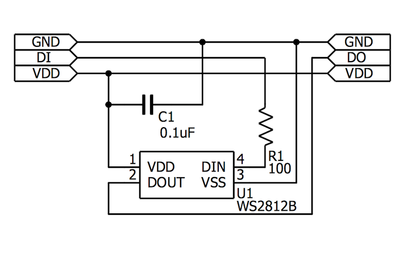
WS2812B data sheet
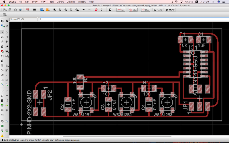
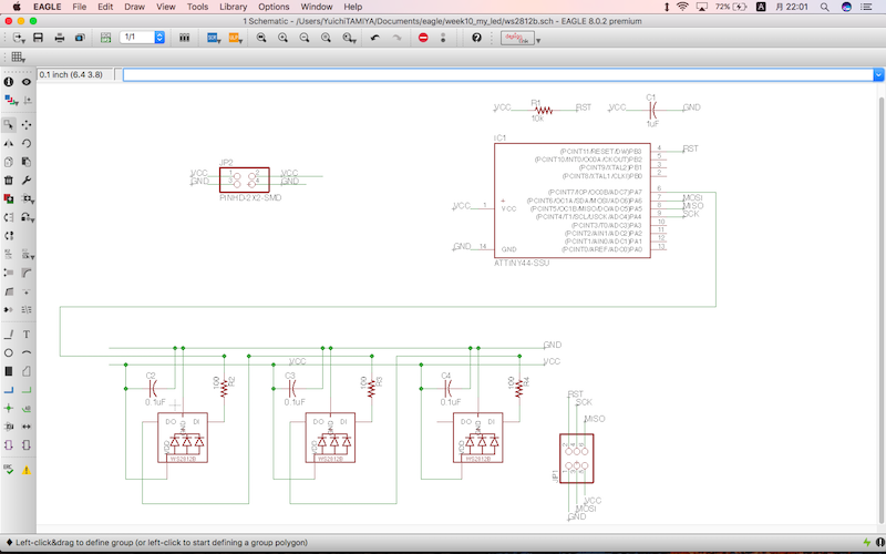
Circuit Diagram
Eagle
download .sch
download .brd
download .png
download .rml
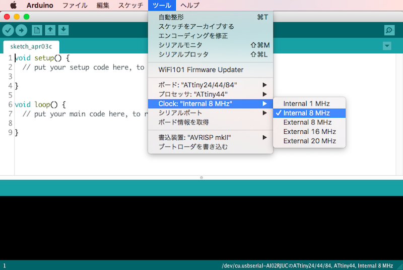
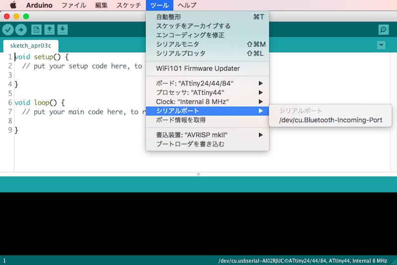
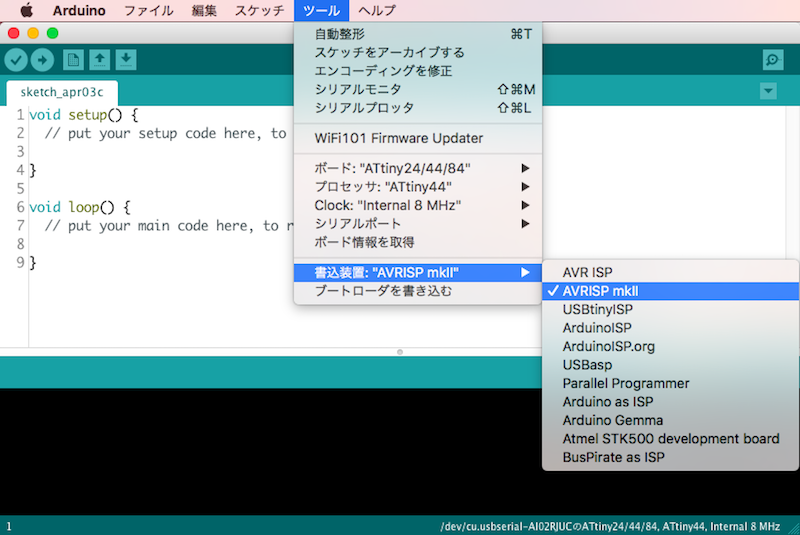
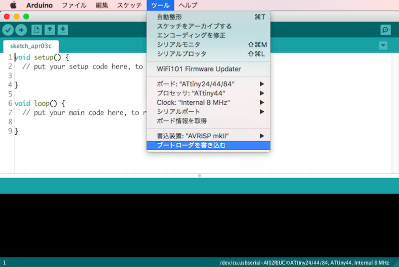
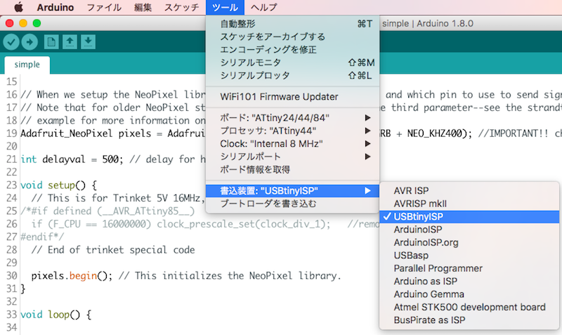
Arduino Compatible To change "my_led board" to Arduino compatible, I followed my week 08 assignment page.
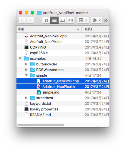
https://github.com/adafruit/Adafruit_NeoPixel
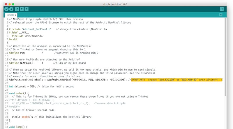
download .ino
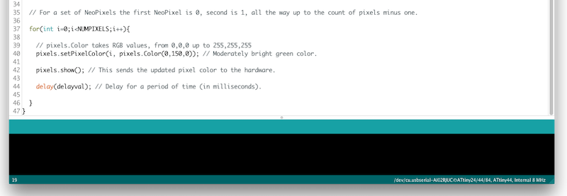
My programming My program is to change LED color like rainbow.
VIDEO
download .ino