program your board to do something, with as many different programming languages
and programming environments as possible
extra credit: experiment with other architectures
Microcontroller Data Sheet
I learned that so many information about the product is included in Data Sheet.
I could not understand as I expect, but I found some information related this week assignment which used in C programming.
10. I/O Ports
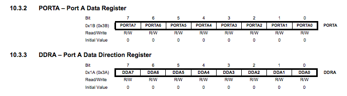
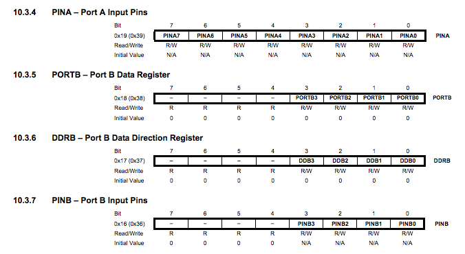
10.1.1 Configuring the Pin
Each port pin consists of three register bits: DDxn, PORTxn, and PINxn. As shown in “Register Description” on page 66, the DDxn bits are accessed at the DDRx I/O address, the PORTxn bits at the PORTx I/O address, and the PINxn bits at the PINx I/O address.
EnglishJapanese.
Connecting Boards
FabISP
(Week04)
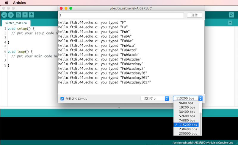
echo hello-world board
(Week06)
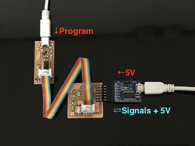
Connecting two boards by ISP cable. Ensure blown line is connected GND to GND.
To use USB-Serial FTDI, Virtual COM Port (VCP) Drivers is needed to be installed to PC.
When FabISP writes program, USB-Serial FTDI supplies 5V to echo hello-world board. After programmed, signals go from PC to echo hello-world board via USB-Serial FTDI.
Arduino Change "echo hello-world board" to Arduino compatible.
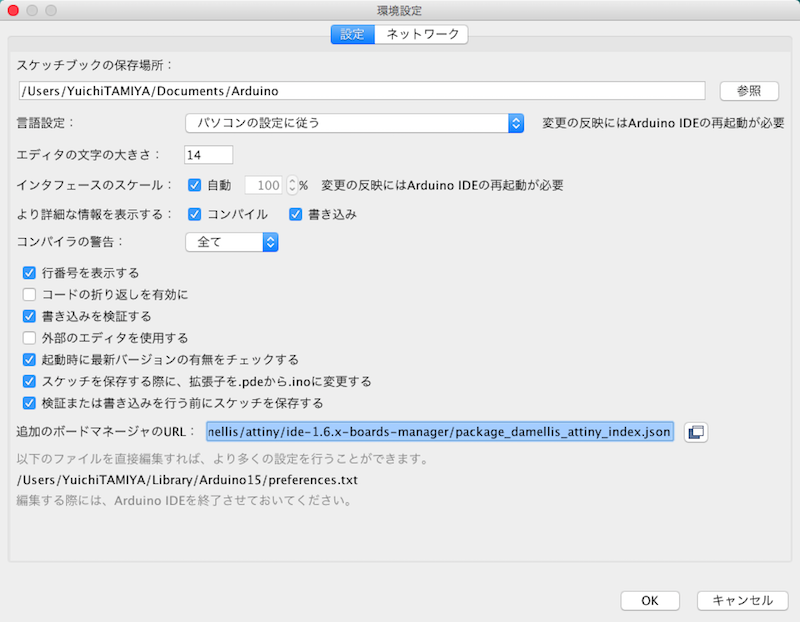
Copy this URL
"
https://raw.githubusercontent.com/damellis/attiny/ide-1.6.x-boards-manager/package_damellis_attiny_index.json ".
Open Arduino IDE -> Preference ->Paste the URL to "Additional Boards Manager URLs".
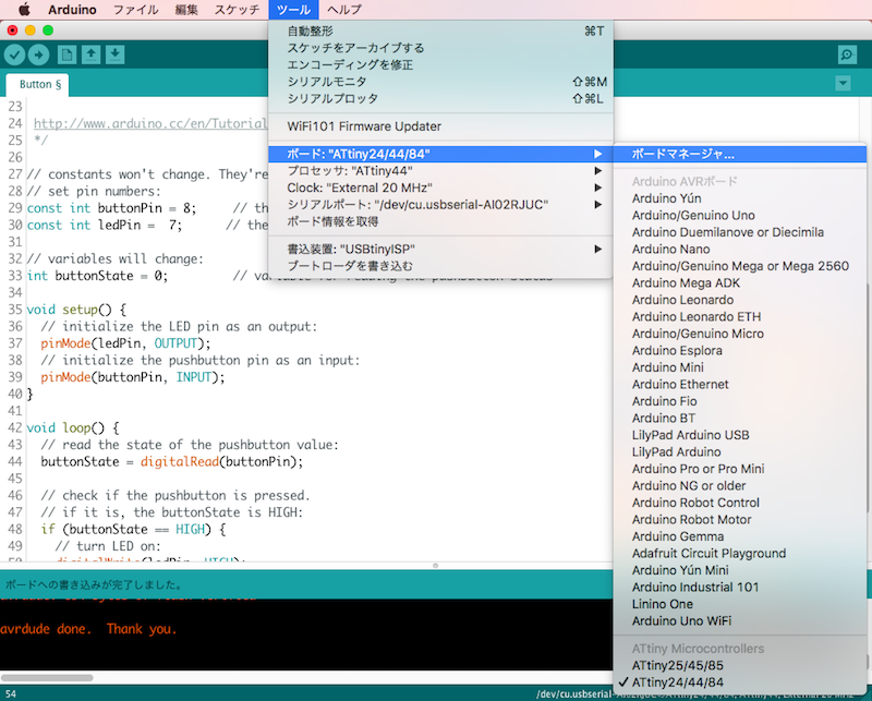
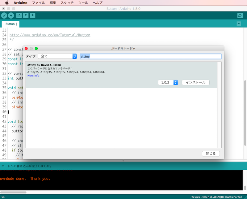
tool -> board -> Boards Manager...
In Filter your search..., type "attiny" and Install "attiny by David A. Melils".
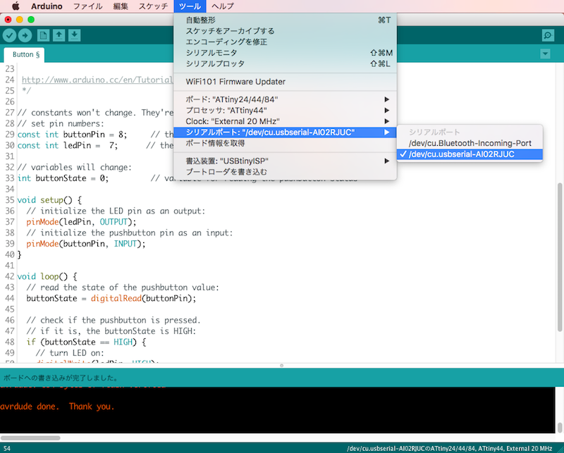
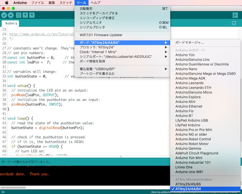
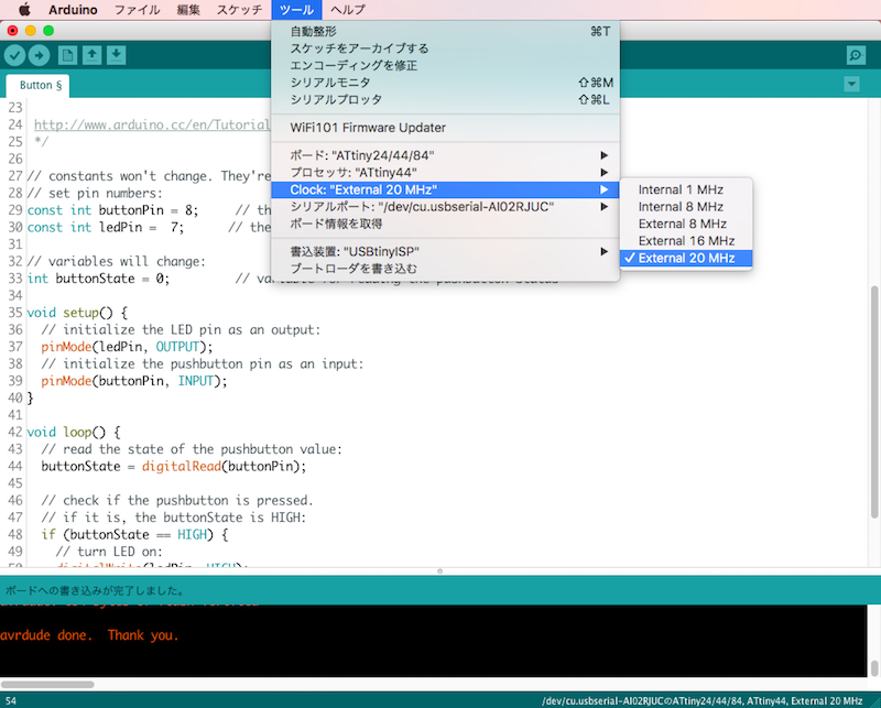
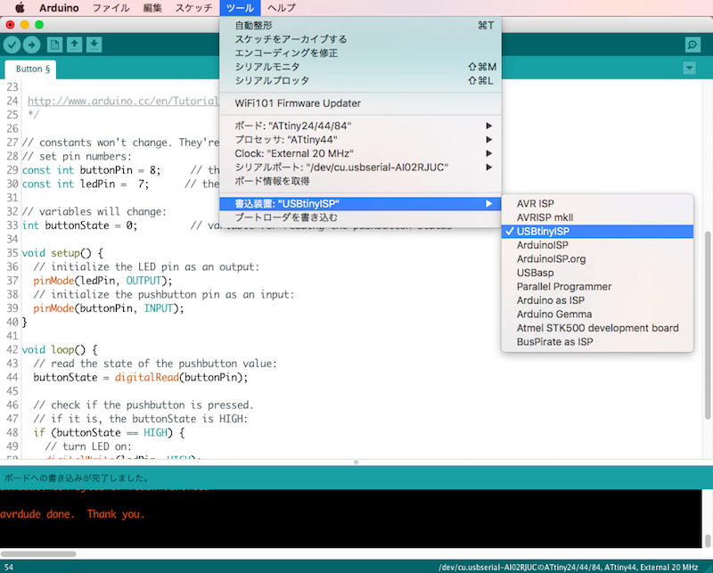
Select Board, Processor, Clock, Serial Port and Programmer.
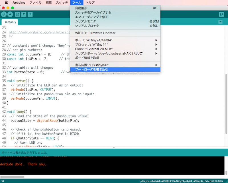
Write fuse-bit to the board.
Programming
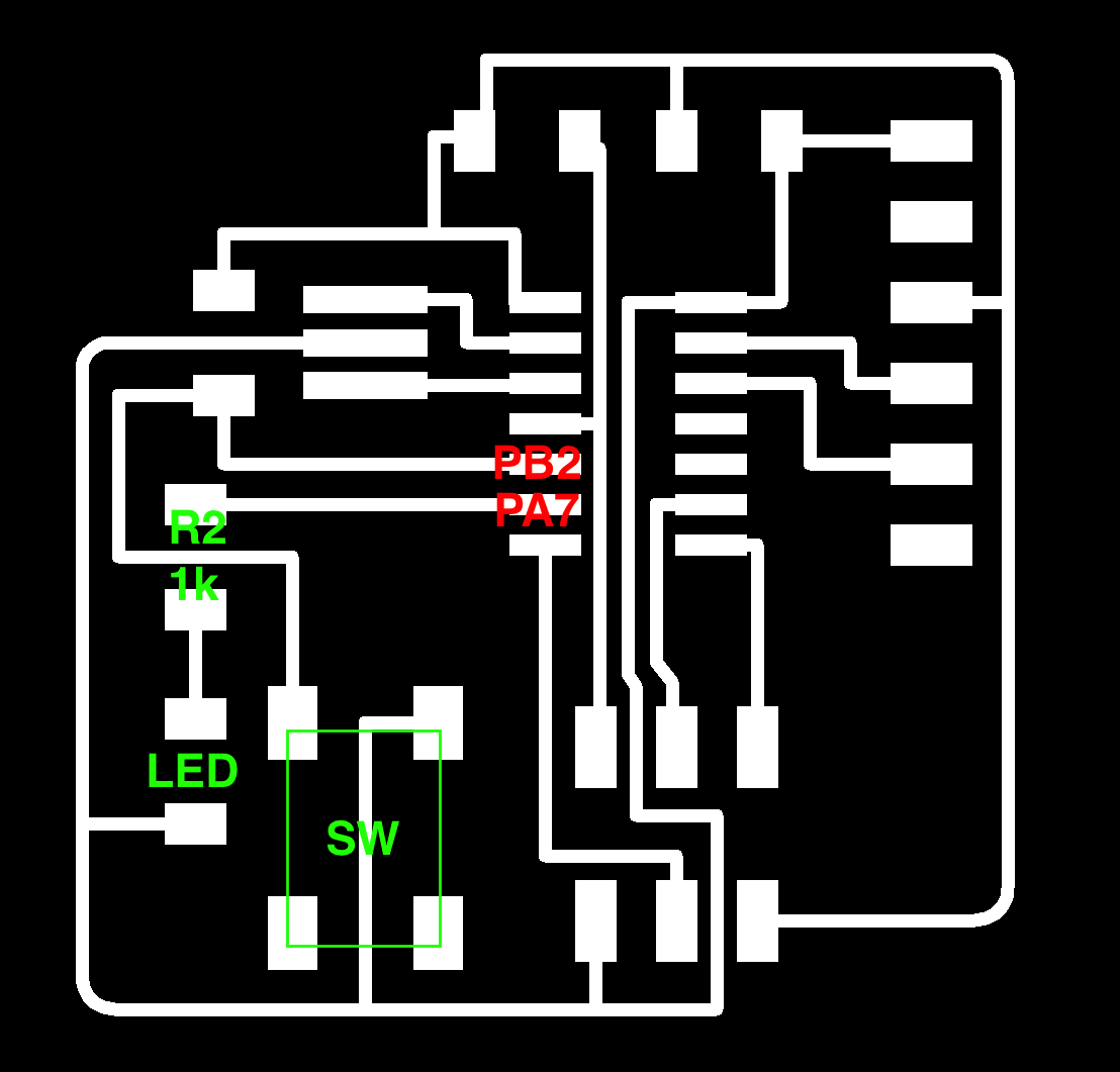
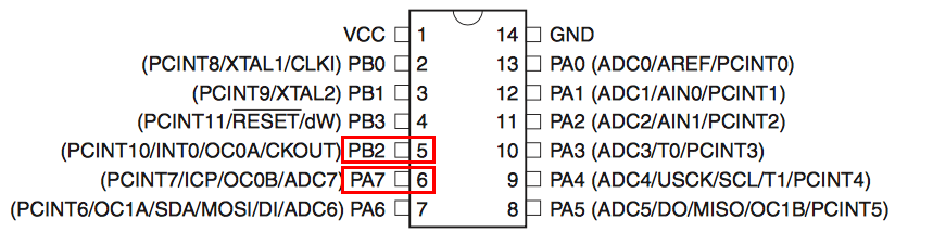
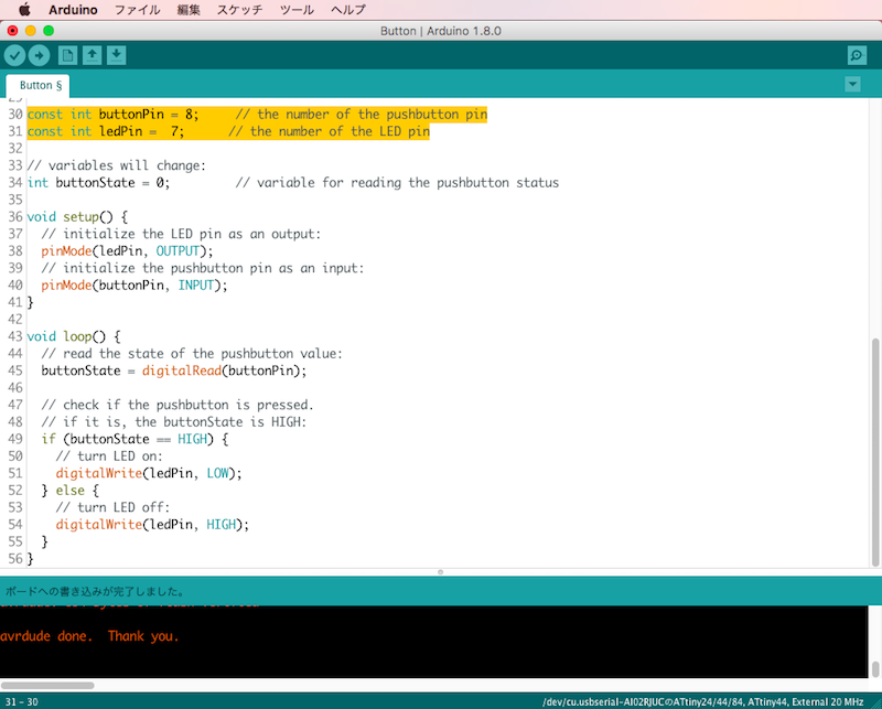
My LED connected PA7 of ATtiny44, which is Arduino Pin 7.
My button connected PB2 of ATtiny44, which is Arduino Pin 8.
Open sample sketch "Button" and change number of the pins.
download .ino
I recognized I designed the button very close to ISP. It is difficult to press button using my finger and see LED light at same time. I need something thin to press.