Week04: Electronics Production
Assignment
- make an in-circuit programmer by milling the PCB, then optionally trying other processes
Brian Zaerc Ali Valentin Andy David
    hello.ISP.44.cad board components traces interior
    hello.ISP.44.res.cad board traces interior
    inventory microcontroller crystal USB connector ribbon connector Zener diode jumper
    firmware.zip
        USB power
        make clean
        make hex
        (sudo) make fuse (check programmer in Makefile, may need to repeat)
        (sudo) make program
        desolder SJ1 and SJ2
        make IDC ISP cable, connecting header pin 1 to pin 1, check wires
    programming
Make milling data
I chose hello.ISP.44.res board. Then I put a mark on to identify which is mine.
Download and opened hello.ISP.44.res's traces data by GIMP.
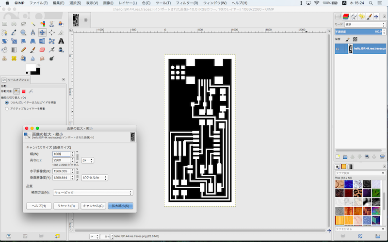
Add a mark on and save as PNG file. Ensure the size and resolution is same as original one.

download .xcf
download .png
I used Fab Modules to make milling data for SRM-20.
Traces
input format -> image(.png) -> select png file
output format -> Roland mill(.rml)
process -> PCB traces(1/64)
machine -> SRM-20
Set x0(mm) -> 0, y0(mm) -> 0, z0(mm) -> 0
cut depth(mm) -> 0.2
Click calculate
Click save
download .rml


I also used hello.ISP.44.res's interior.
Interior
input format -> image(.png) -> select png file
output format -> Roland mill(.rml)
process -> PCB traces(1/32)
machine -> SRM-20
Set x0(mm) -> 0, y0(mm) -> 0, z0(mm) -> 0
cut depth(mm) -> 0.6
Click calculate
Click save
download .rml
Milling
I used SRM-20.
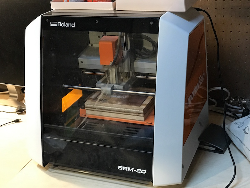
Press to power on (green light)
Click VPanel for SRM-20 icon
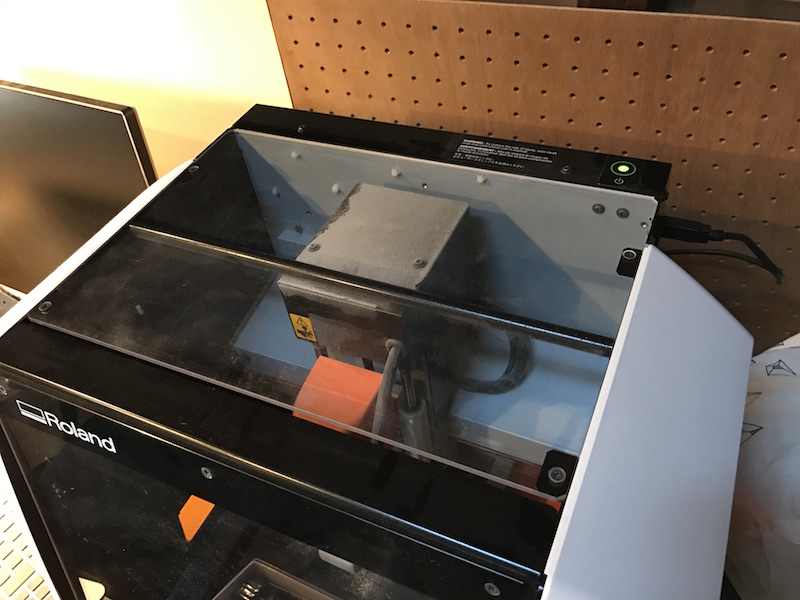
then open window and press view to move the head

Set endmill with an allen wrench
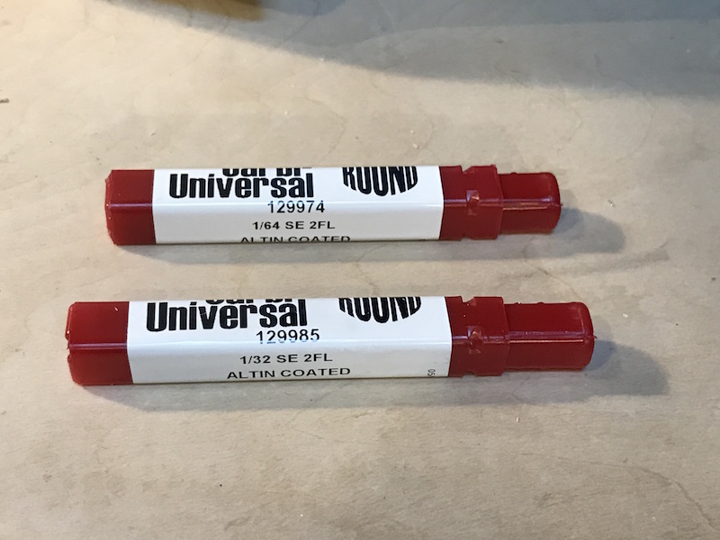
Endmills, 1/64 and 1/32.
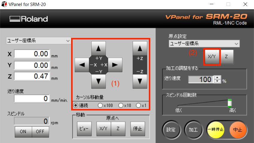
Move the head to the place where I want to start milling on PCB.(1)
Set Origin Point X/Y.(2)
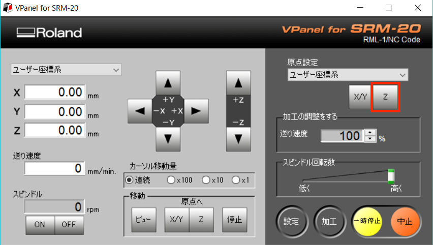
Set Z point by touching endmill to PCB.
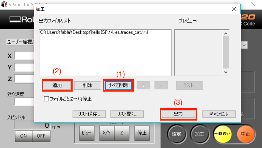
Click Cut to open to choose file
(1)Delete all
(2)Add
(3)Output
then start milling.
Milling

After finishing traces by 1/64, start interior by 1/32 using same XY Origin Point. Set Z Origin Point again for 1/32.
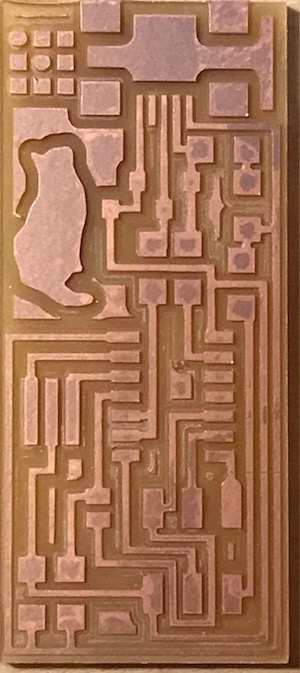
Milling finished.
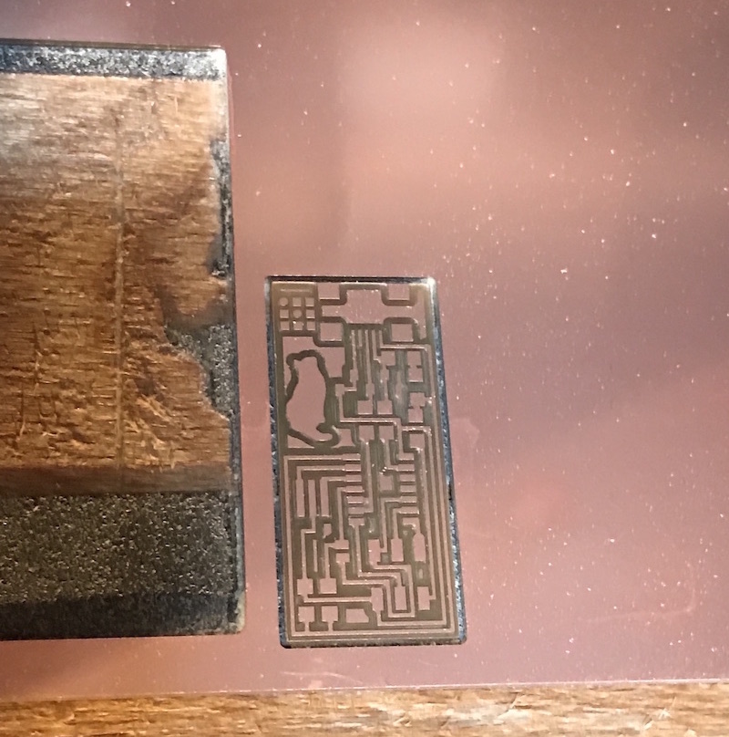
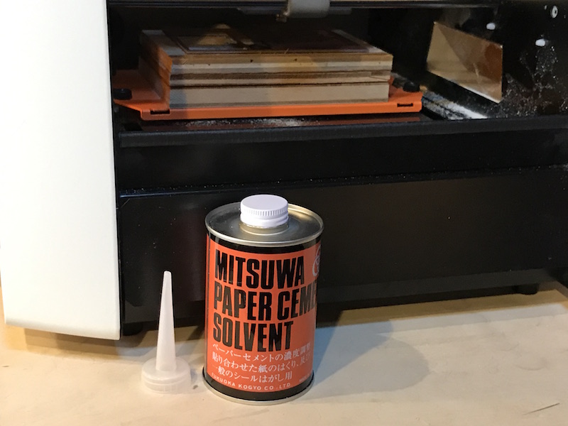
Use Solvent to take out
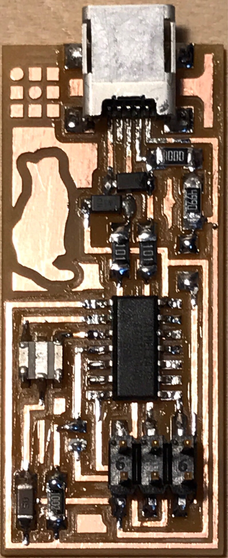
My fabISP
Soldering
After washing FabISP, put flax on, then start soldering.
Solder USB jack first, Attiny 44, other tips and Pin header the last.
|
| |
|
|
|
|
| R1: |
Resistance |
1k [ohm](1000) |
x 1 |
| R2: |
Resistance |
499 [ohm](4990) |
x 1 |
| R3,R4: |
Resistance |
100 [ohm](101) |
x 2 |
| R5: |
Resistance |
10k [ohm](1002) |
x 1 |
| C1: |
Capacitor |
1u [F] |
x 1 |
| D1,D2: |
Zener diode |
3.3 [V] |
x 2 |
| IC1: |
Attiny 44 |
|
x 1 |
| 20MHz: |
Resonator |
20M[Hz] |
x 1 |
| SJ1,SJ2: |
Wire |
|
x 2 |
| J1 ISP: |
Pin header |
2x3 |
x 1 |
| J2 USB: |
USB jack |
|
x 1 |
|
|
|
|
Preparing an ISP
I used Arduino Uno as an ISP to program Fab ISP.
( ISP = In-system Programmer)
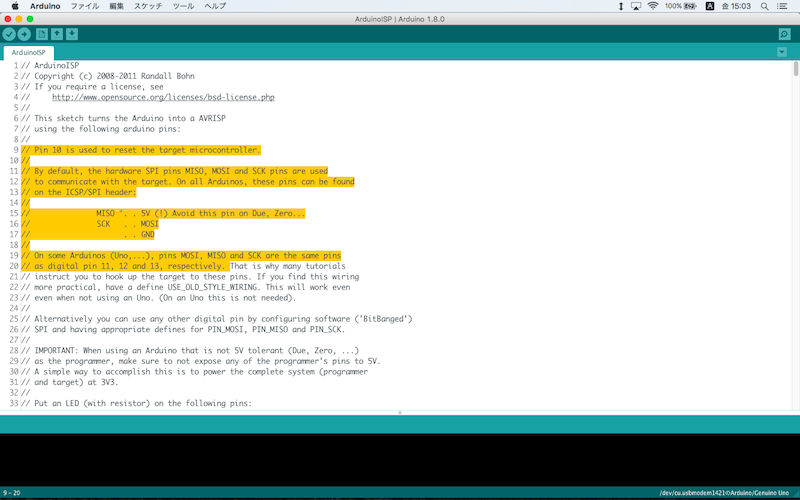
In Arduino IDE, Open File -> Examples -> 11.ArduinoISP ->ArduinoISP

Connect Arduino to Mac, then upload ArduinoISP to Arduino.
Preparing make Fab ISP as programmer
Download and Install CrossPack for AVR to Mac.
Download and Install Xcode to Mac.
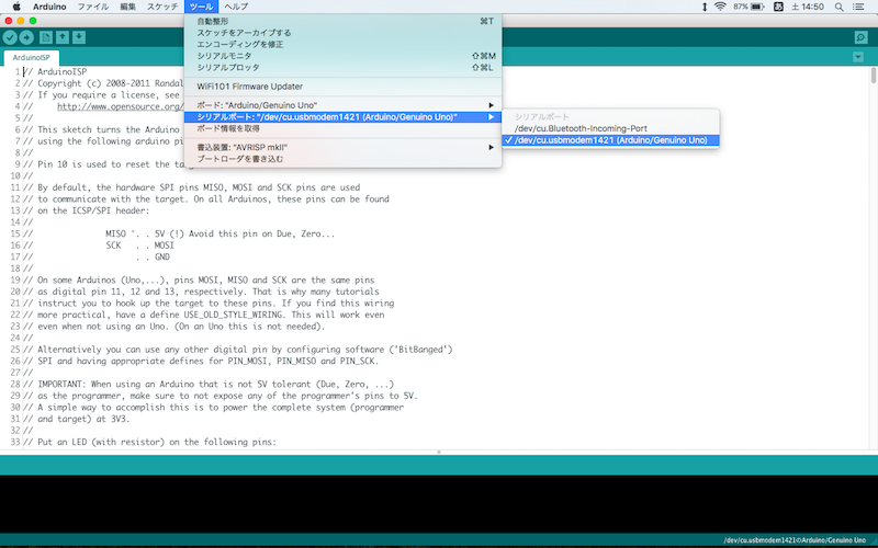
To find my PC's port, open the Arduino IDE, and check under Tools > Port.
The port is /dev/cu.usbmodem1421.
Download firmware.zip and unzip on Desktop which is fabISP_mac.0.8.2_firmware.
Open fabISP_mac.0.8.2_firmware -> Makefile
In Makefile, add a line below and save;
AVRDUDE = avrdude -c stk500v1 -b19200 -P /dev/cu.usbmodem1421 -p $(DEVICE)
Two "AVARDUDE = " line above should be commtent out by using #.

download Makefile
Confirm the PATH through
From Tarminal,
$ echo $PATH
/Library/Frameworks/Python.framework/Versions/3.5/bin:
/usr/bin:/bin:/usr/sbin:/sbin:/opt/X11/bin:
/usr/local/CrossPack-AVR/bin
/usr/local/CrossPack-AVR/bin is added.
Wiring Arduino to FabISP
Read connecting information in ArduinoISP.
Wiring Arduino to FaB ISP
| Arduino Uno |
Fab ISP |
| 10 |
RST |
| 11 |
MOSI |
| 12 |
MISO |
| 13 |
SCK |
| 5V |
V |
| GND |
GND |


Program the FabISP
From Terminal,
$ cd Destop/
$ cd fabISP_mac.0.8.2_firmware/
$ make clean
$ make hex
$ make fuse
$ make program
This is the response from system.
Verify FabISP
Apple menu on tool bar ->about this mac -> system report -> System Profiler -> Hardware -> USB -> Hub
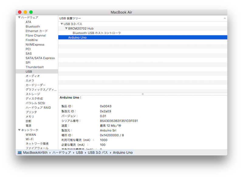
"FabISP" should be listed in the hub menu, but still Arduino Uno instead.
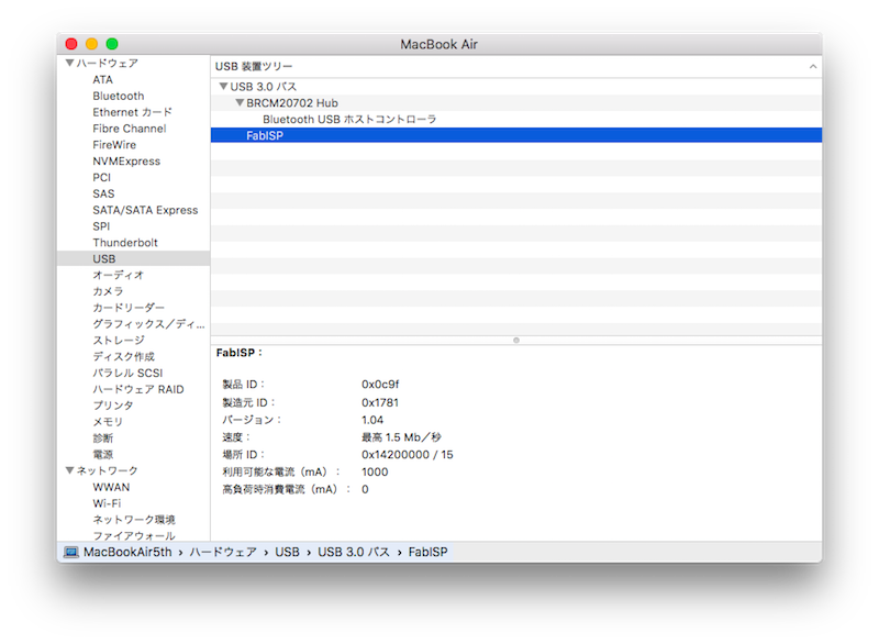
Desolder two jumpers, SJ1 and SJ2.

Then "FabISP" is in the list.
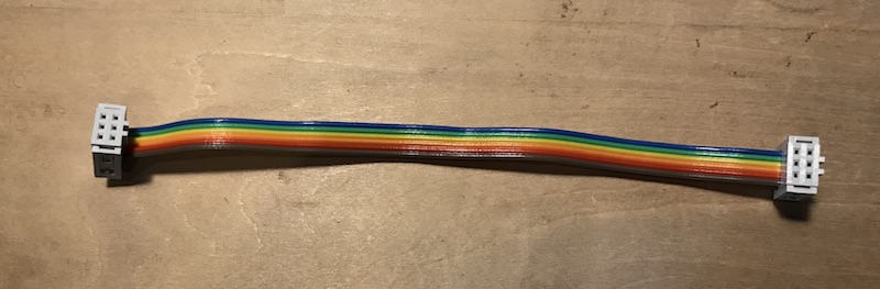
Make cable
I checked the cable by using tester.
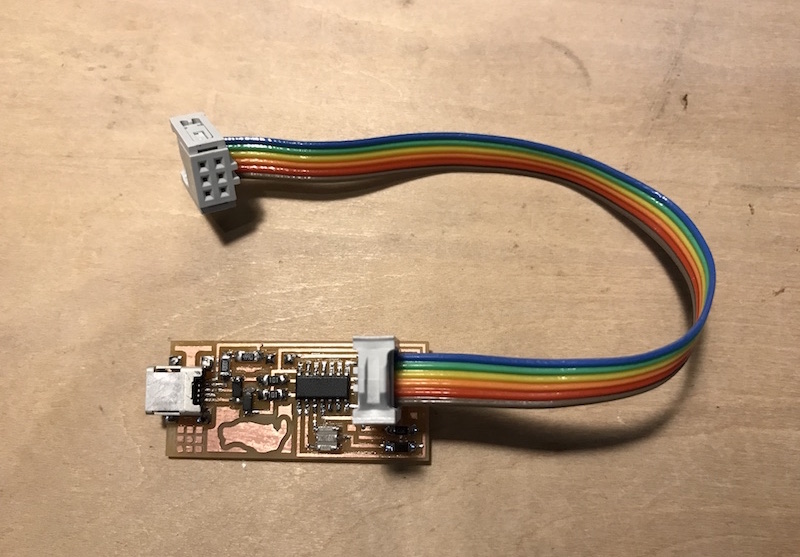
My FabISB
Using AVRISP
When AVRISP is used instead of Arduino, connect two wires as below. One is PC to AVRISP. Another Mini USB cable from PC is needed to supply power to FabISP.
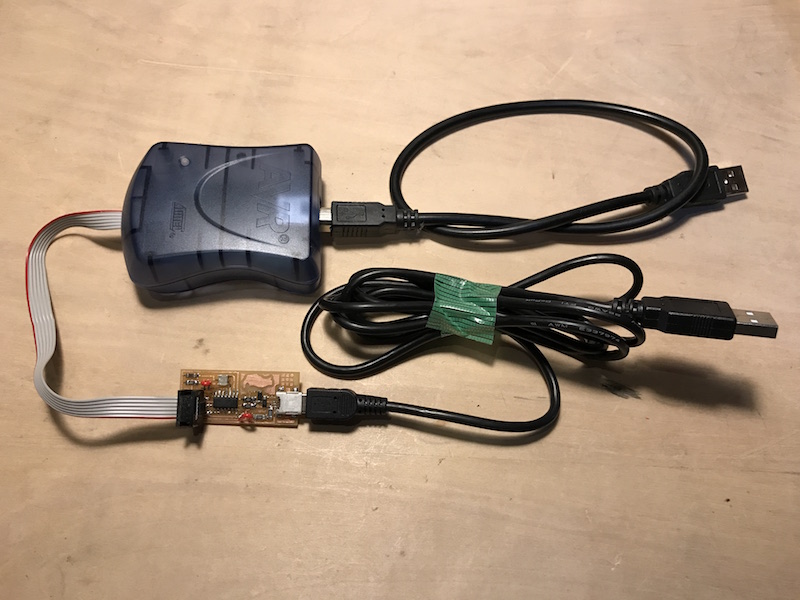
Use different line of "AVRDUDE =" in Makefile.

