Week #5 3D Scanning and Printing
Assignments
Software Used
Machine Used
- Zmorph 2.0 SX
- Sense 3D Scanner - 3D Systems
- Mousta Builder (Made in Brasil)
- Lenovo Moto Z Play camera
Exercise Repo
You can find all files used in this class in the Fab Academy repository in the button below or a backup in this Google Drive folder.
Past experience
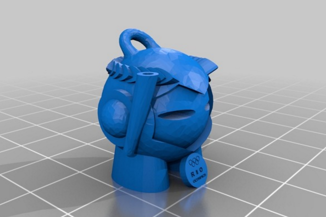
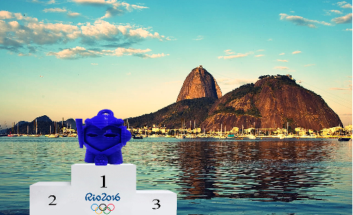
From the whole set of Fab Lab machines and tools, 3D printer is the one that I'm most familiar with. I had built my own 3D printer on 2014 and since that I’ve been printing some stuff. The image below shows a model (made on Tinkercad) that I did for the Olympic games. It is available on ,thingiverse.
3D printing technological advantages
This article from 3D hubs summarizes the mais advantages of 3D printing when compared to traditional manufacturing techniques. For me, the best thing of 3D printing is that it allows a large amount of design freedom and means that very complex geometries can easily be created in a single step manufacture (no raw material preparation, no fastening). Because components are constructed one layer at a time design requirements such as draft angles, undercuts and tool access do not apply when designing parts to be 3D printed.
Log
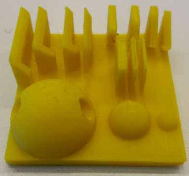
2017 02 28 Group Project and first tests with 3D scanner
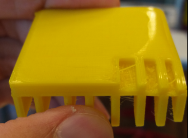
As group project, we did a model to test some parameters of our 3D printing. My colleague, Daniel Krás, led this task, since he was the most experienced one of our team. It is documented on his website. The 3D model was design in Fusion 360. The pictures below show the results that we got.
3D print parameters:
- Nozzle temperature: 240°C
- Bed temperature: 100°C
- Layer height: 0,1 mm
- Printing speed: 30mm/s
- Material: ABS
- Glue to the printing bed: Karina hair spray
With this test I learned the recommended parameters to use in the Zmorph machine combined with the material we had available. I used these parameters as reference for other 3D printings.

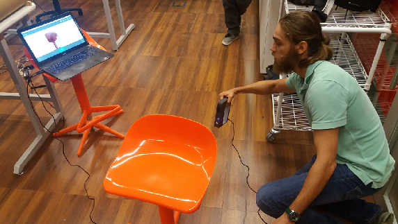
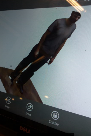
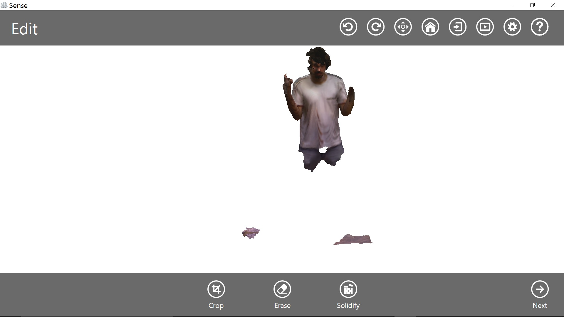
We also did the first tests with our 3D scanner, a Sense 3D. First we had to install the software (it takes some time, and require a good computer). To scan was very intuitive. The problem was that we "lost the track" a lot of times while scanning, and we couldn't get a good model done in the end of the day. The pictures bellow show this process and the outcomes we got.
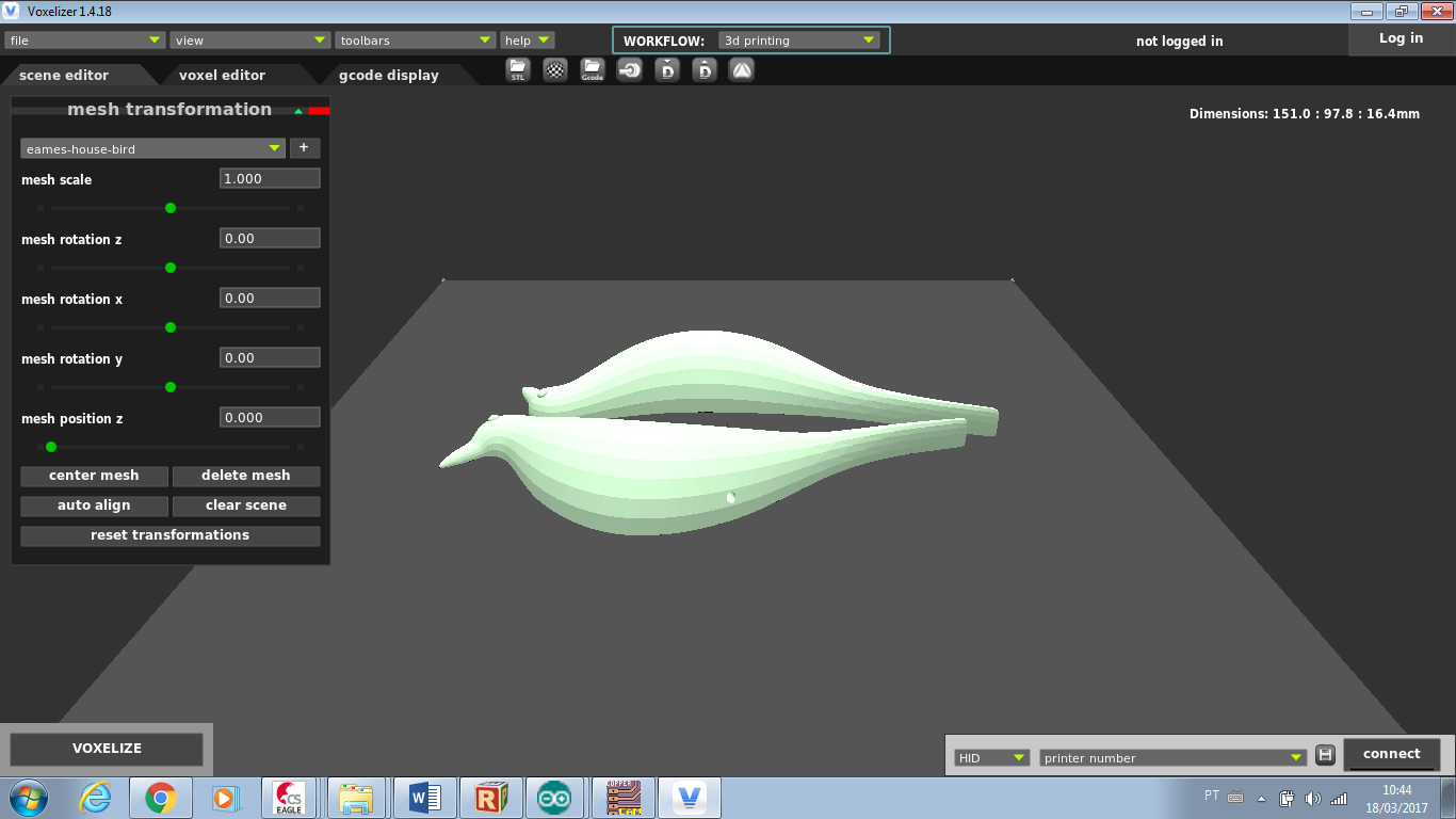
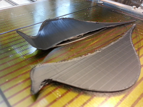
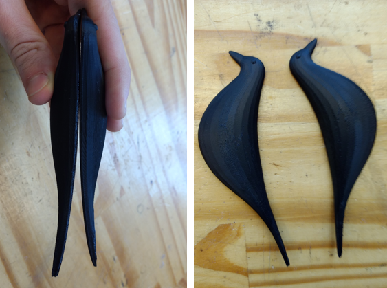
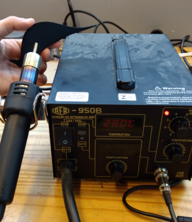
2017 03 18 3D Printing Eames Bird House
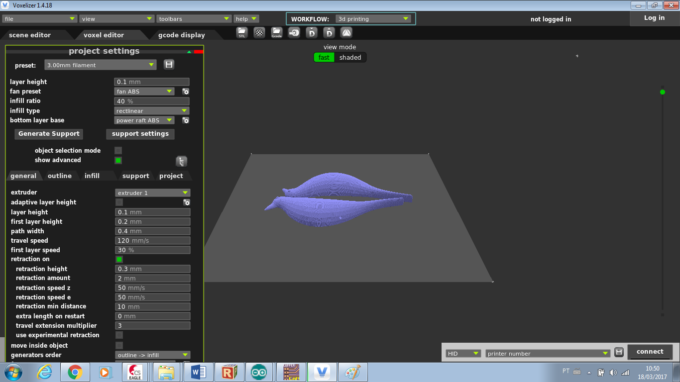
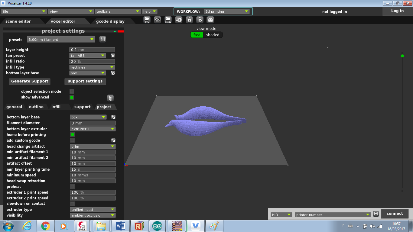
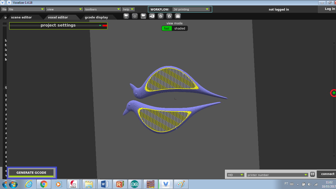
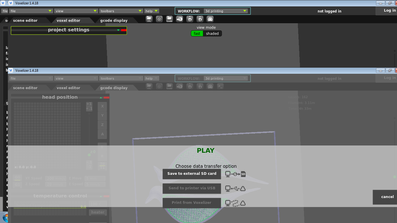
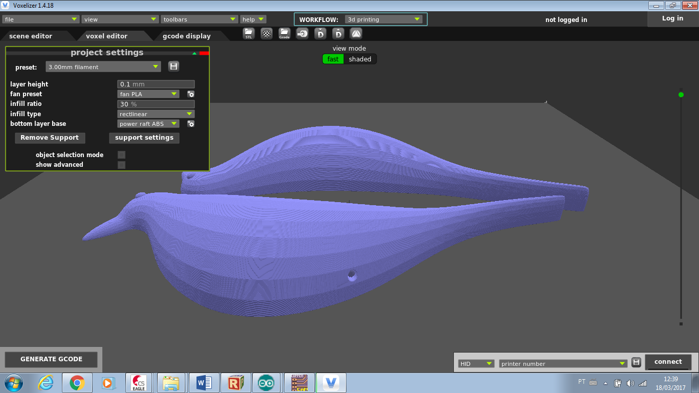
Even though I've used 3D printers before, this was the first time I used Zmorph and its proprietary software, called Voxelizer. The process was almost the same I was used to. My main difficult was to find the features on this new software. The first step was to import the stl file. I decided to make a black bird to decorate my room. I found a 3D model on Thingiverse, called Eames Bird House. The next step was to set printer parameters, and then generate the G code to slice my model. With the G code done, it's possible to check the layers of the sliced model to look for some issues that you might have (e.g. the 3D model has detail impossible to reproduce with the printing resolution set). Last step in the software is to export generated file (in this case in a gcode extension) and save it in a SD card to communicate with the machine.
To print I used ABS 3.0mm black, and the main parameters were:
- Nozzle temperature 240ºC;
- Bed temperature 100°C;
- Layer thickness 0,1 mm
- Printing speed 30mm/s.
The images below shows the all the parameters set.
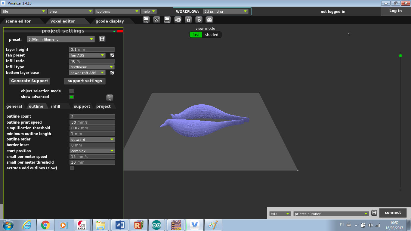
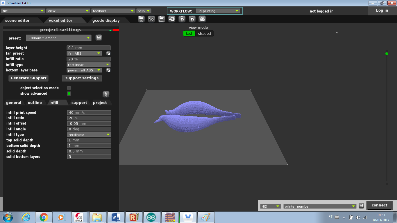
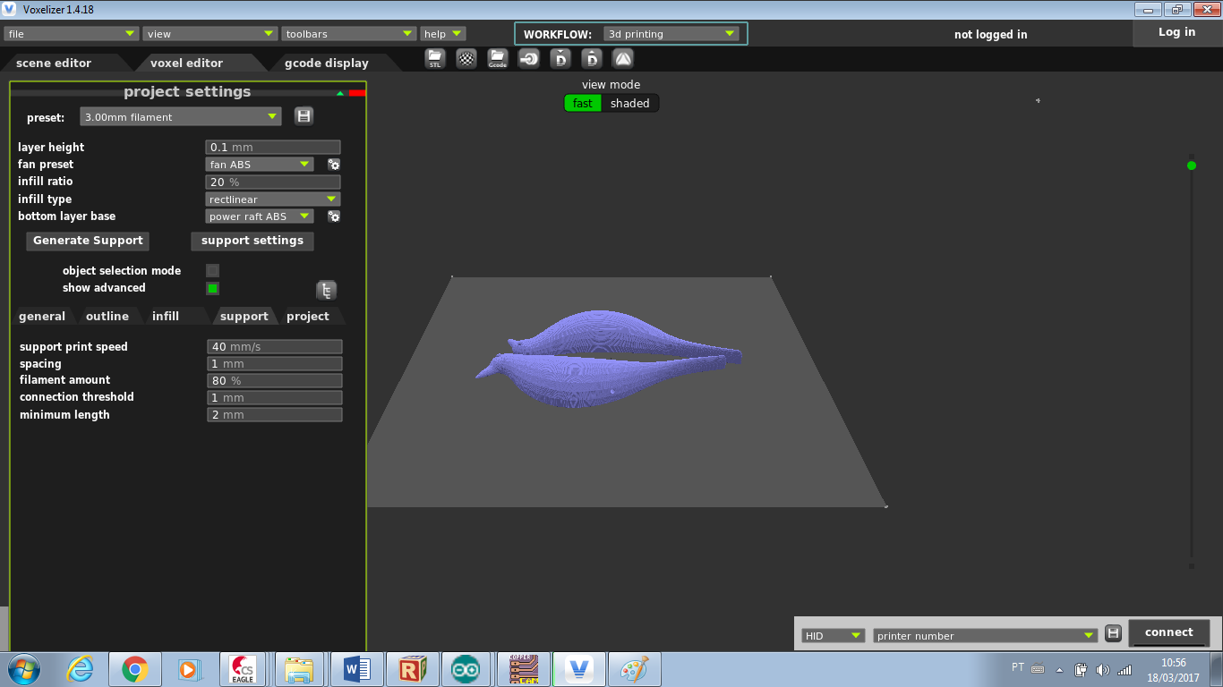
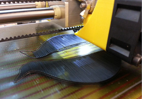
As I had an issue with the first printing, I tried to fix it by changing the support type to power raft abs and also by reducing the temperatures:
- Nozzle temperature 235ºC;
- Bed temperature 90°C;
The outcome was not perfect but good enough. It was a little bent, but I liked the swallowtail effect.
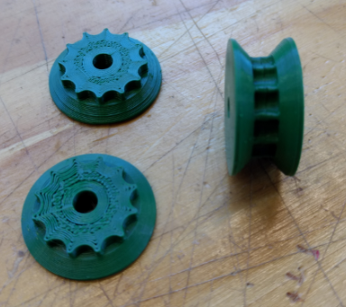
2017 04 06 Using Mousta 3D Printing and Repetier
As part of Mechanical Design I used Mousta and Repetier slicer software to 3D print a pulley. This process is documented on exercise 9page, 2017 04 06 log. The settings used on Repetier is available on Google Drive folder of both exercises, named as "mousta_config.ini".
2017 04 08 Assembling Eames Bird House
As the 3D model was split into two parts, our instructor, Kenzo, suggested me to use a thermal blower to heat it and try to glue the two parts. He show me the process in a small pulley, but I didn't succeed doing it in the Eames bird house. I found it a very slow process, difficult to do in big surfaces, easy damage parts finish, and also easy to burn yourself with hot air. In another occasion I will try a different process. The pictures bellow presents it.
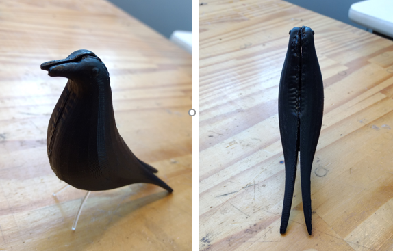
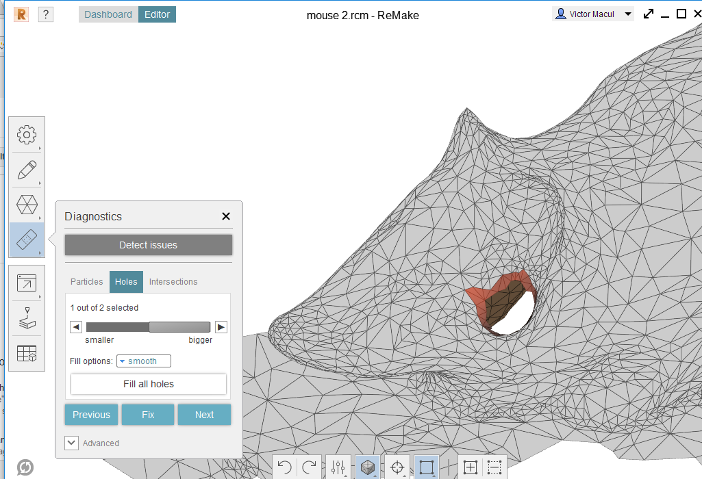
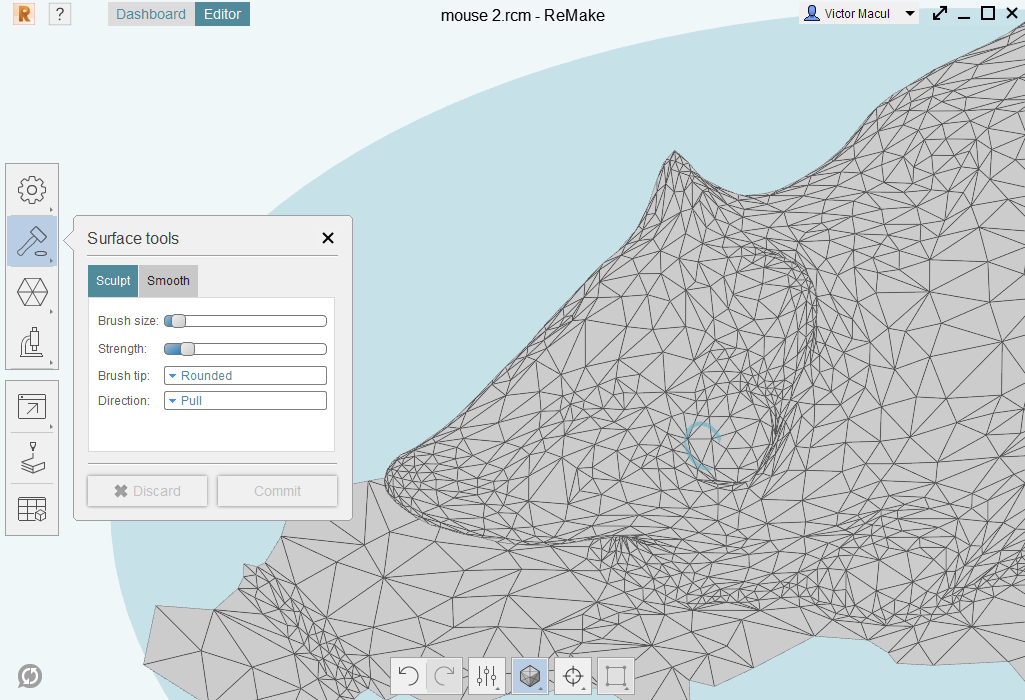
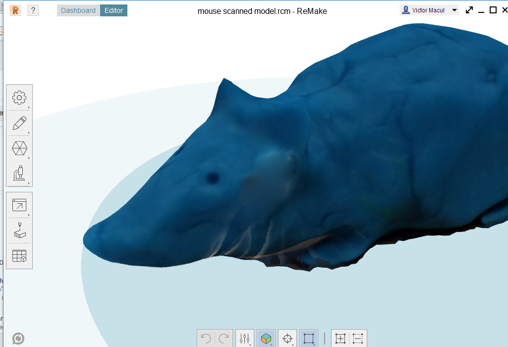
2017 04 28 Trying Autodesk ReMake + smartphone camera to scan an object
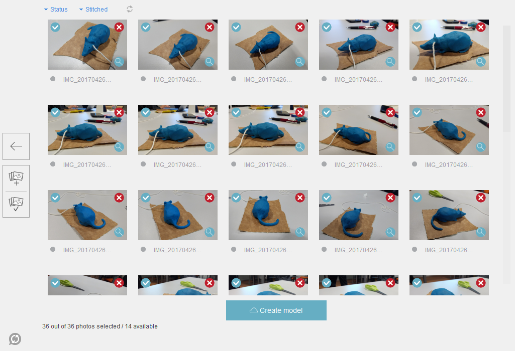
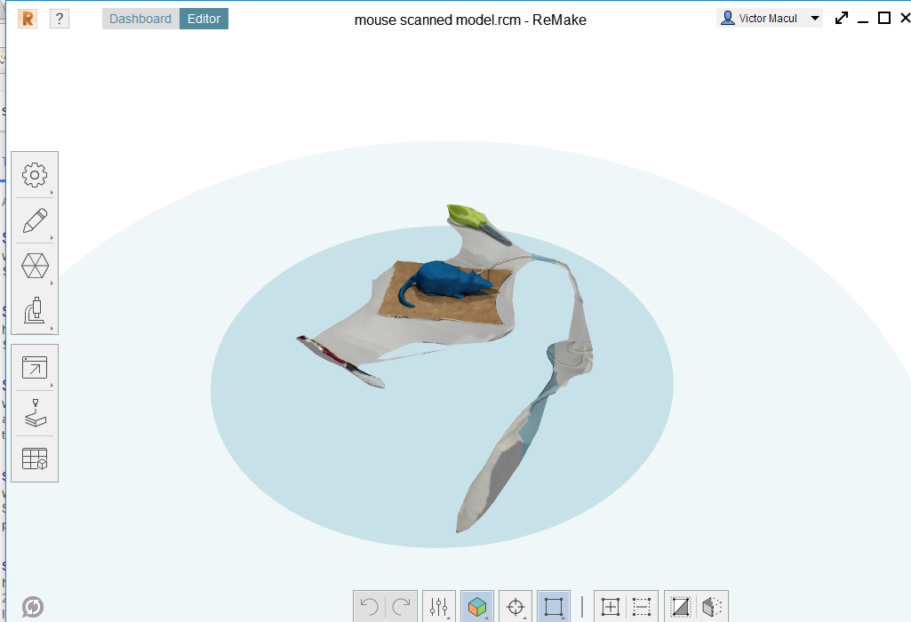
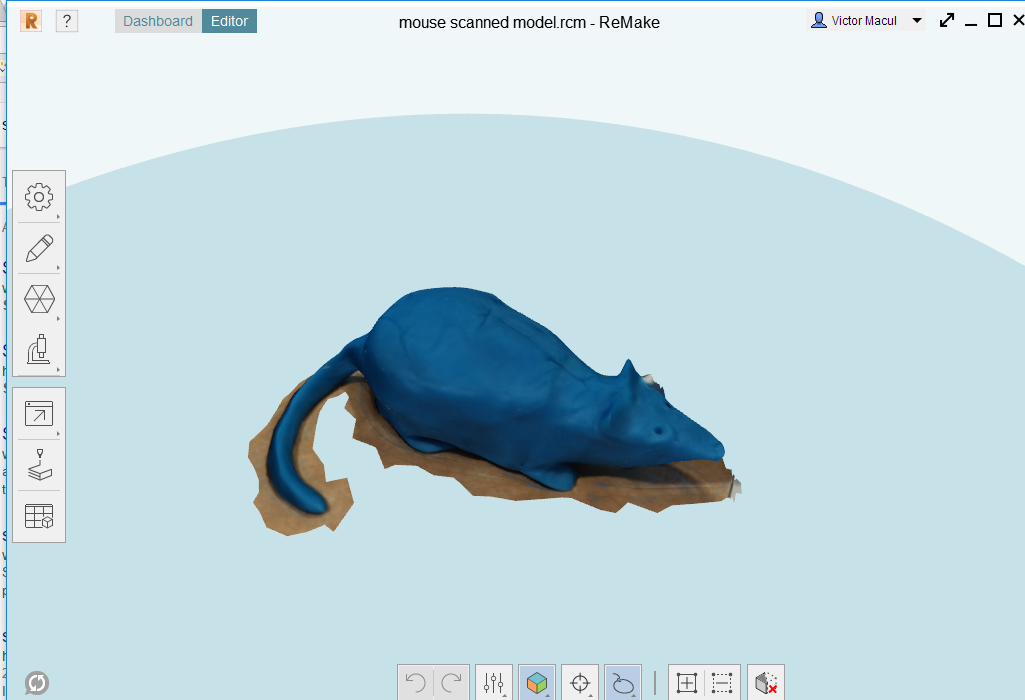
Before talk about how I did this process, I'll contextualize about why doing this object. During past week, my students had to build a rough prototype of the toy they are designing for K12 kids (part of the course I teach with more four colleagues). One group decided to design a play which a remote control tiger has to catch a mouse that moves at random. As a part of the prototype, they built a mouse using play dough. It is object that I scanned. My intention was to show them an application for this tool on the project. The picture bellow shows the original play dough model, and the 3D scanned one.
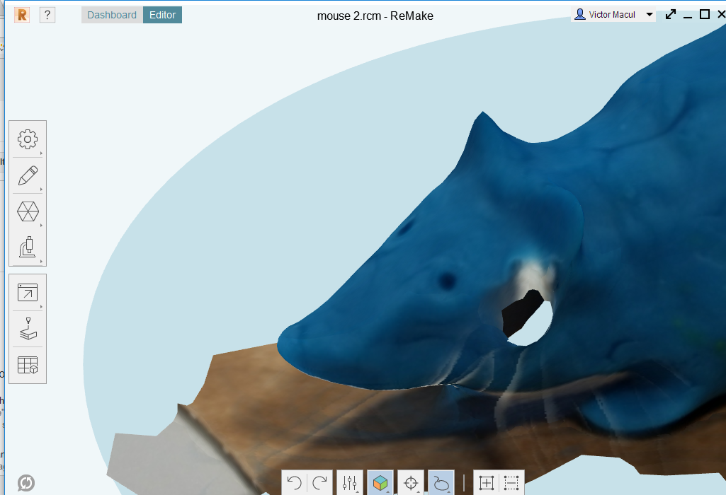
To do this a took 36 pictures of the play dough mouse prototype with my smartphone and upload it on Autodesk ReMake. To use the software was very intuitive. I recommend to watch this tutorial video to be aware about the workflow and main features of the software. The process is summarized in the follow steps: (1) select just the volume that you want on the 3D model originally generated, (2) fix some parts (holes and some surfaces using repair feature, and sculpt and smooth brushes) and (3) export the file in the format you want (I did .obj to open on Fusion 360 and .stl to see how it would be printed on Repetier). The pictures bellow illustrate this process.
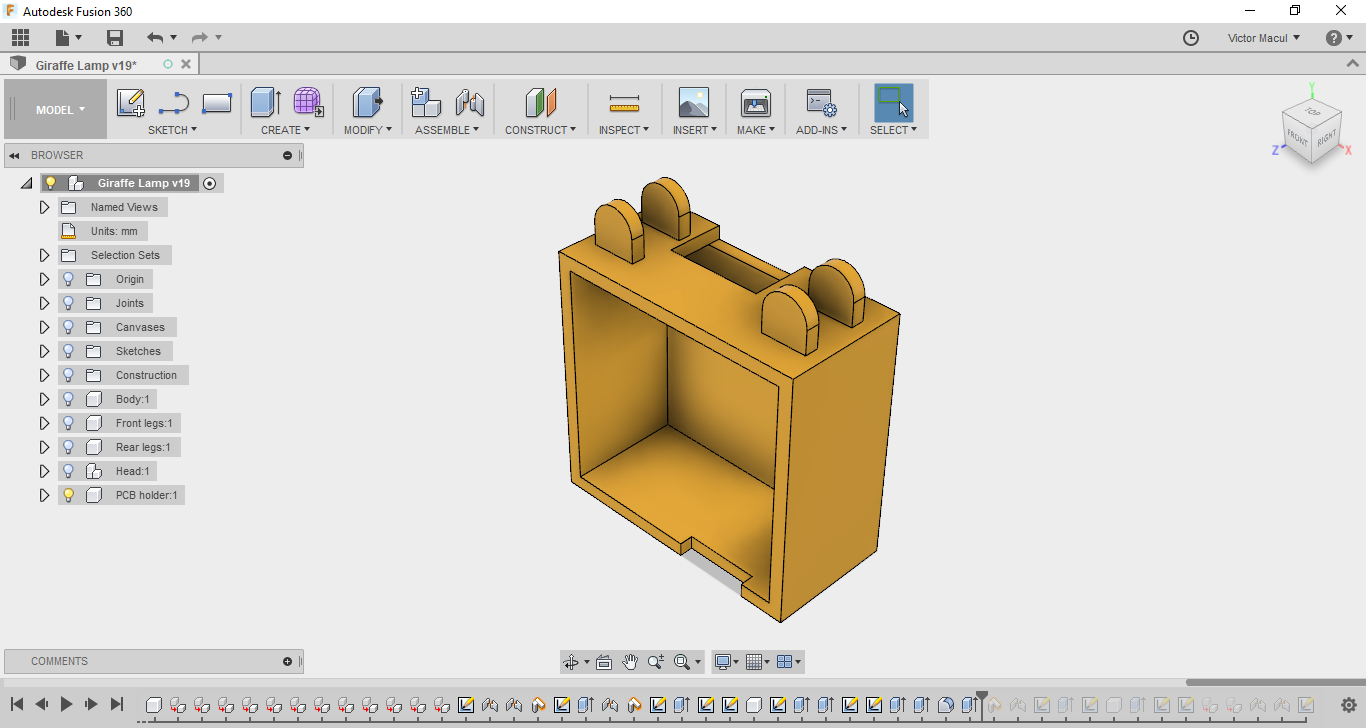
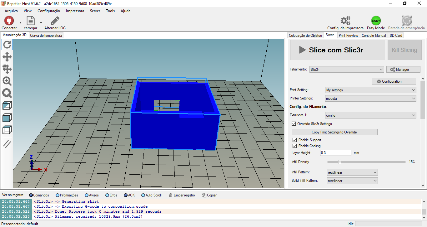
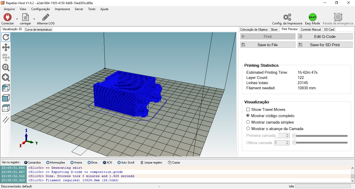
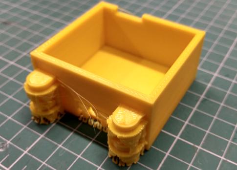
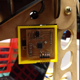
2017 06 19 Making a PCB Holder
For my final project I had to build a part to hold my dimmer shield and microcontroller board and mount it on the Giraffe Lamp head. The design process for this object is described in the Exercise 02 and in the pictures bellow show the settings I used to print it in Mousta Builder machine. This object is an example of a piece that is much easier to do by 3D printing (considering the machines available in Fab Lab), since it has a specific profile in more than one plane. To do it in a 3 axis CNC milling machine would be necessary to change the clamping workpiece once, and doing it I'd take the risk to loose the reference. After print the PCB holder, it was necessary to file a little to fit the board perfectly.