Interface and Application Programming

A little bit of processing

The tasks asked are:


- Write an application that interfaces with an input and/or output device that you made, comparing as many tool options as possible.

Class material: Interface and Application Programming

For this assignment, I chose to work again with the thermosensor (check exercise13 for extra information). The idea was to read data and plot a graphic with processing application. As I had my code 'serial printing' information in the screen, it took me a while to learn I couldn't busy at the same time Arduino and Processing softwares with the same USB por connection (com3 in my case).

Where I learned about processing?


- It has a website: processing.org.
--- Download link
--- Tutorials link
--- References and exemples link

Assignment report

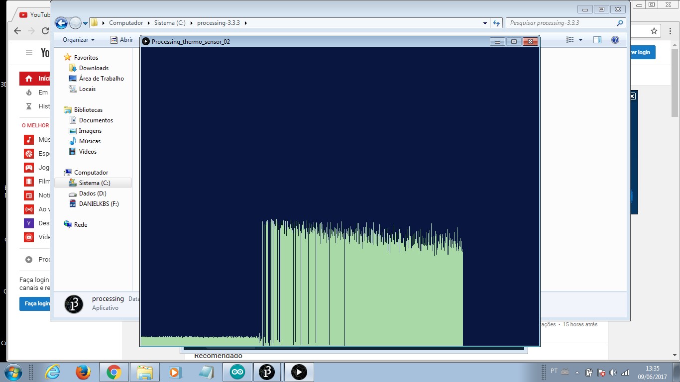
I read about some exemples that were available at the website and chose one. My intention was to plot a graphic in my computer that showed temperature measurement. The idea was to see the temperature change clearly. As the ar conditioning inside the lab was getting inside temperature cold (19°C) the simple 'holding thermosensor' tight made a significantly change in the reading value. That change is to be recognized in the graphic.

The assignment workflow is:
- Learn Arduino to Processing.
- Implement an Arduino code.
- Implement a Processing code that relates to previous Arduino code.
- Check results on screen.

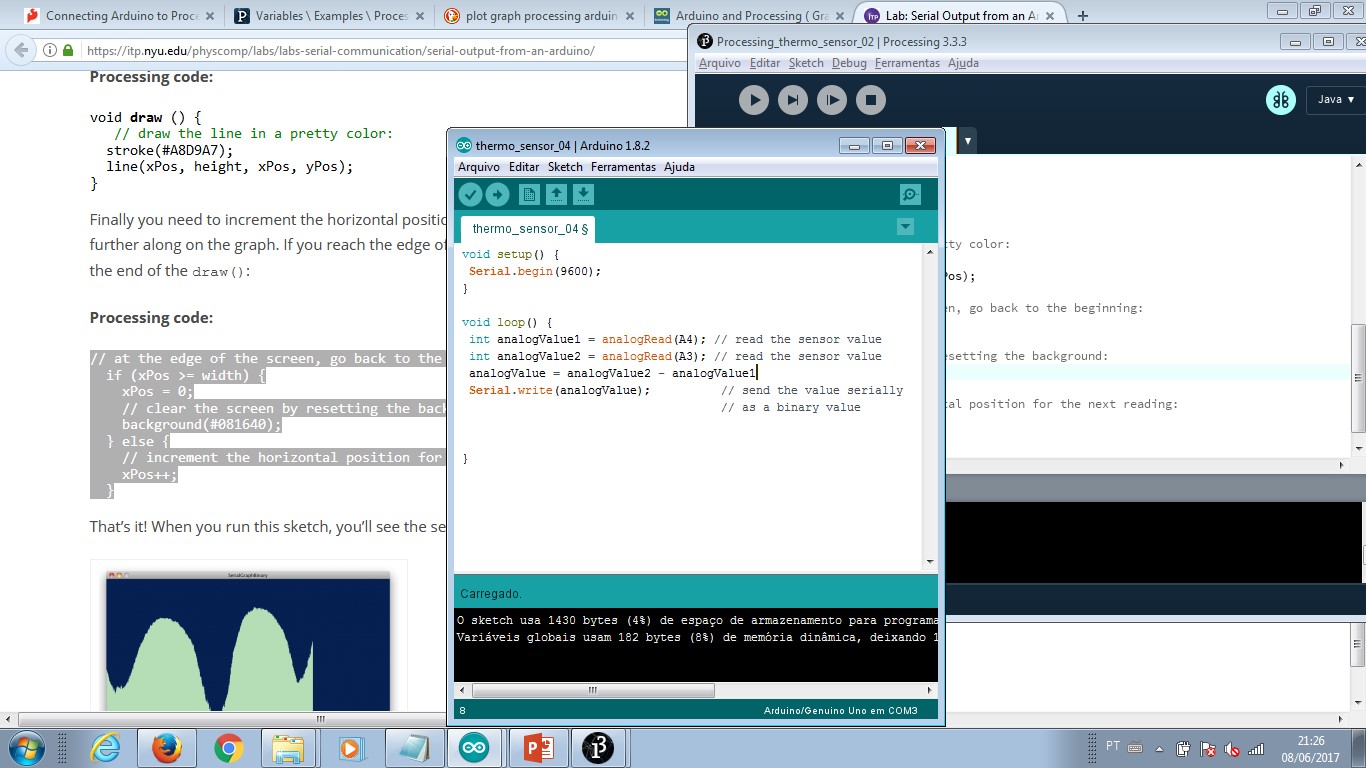
In order to implement this exercise, I searched and customized an online available solution (link below). After I finish the Sparkfun tutorial, I iniciated working on this second code. There is the need to adjust serial comunication in Arduino and Processing codes. Seria read is important because that is the port I used to receive information from themosensor. The frequency this data flows has to match in Arduino and Processing codes. The computer COM port has to be set in order to get in Processing display the correct read. Otherwise, the result will be null or error message. I had all this problems and, one by one was adjusting and seting the code to make it work.

Customize also means colour and time to refresh screendata. There is a condition inside the reading loop that 'cleans' the graphic area reseting the inicial background colour. To get the information and the change in temperature clear in the display - graphic - the data plot colour must contrast with background colour.

Reference link: ITP Physical Computing Lab: Serial Output from an Arduino to Processing.

Processing thermosensor signal - searching for an exemple and ideas from the internet.

Learning processing - how to integrate a code programmed for a microcontroler via Arduino and having it as a source to process information with Processing software.

First result – tutorial – sparkfun processing arduino.
- Processing code here.

Dealing with processing. It took me an hour to understand processing will work with the last programming code I loaded to my microcontroler and it will only work after I stop it in Arduino software (serial conection display + read) to start it in Processing (same otherwise).

Website reference; editing arduino code; editing processing graph.

Processing data.
- Data is amplified in order to have a highter step between cold and hot.
- There is a delay in the reading process (set by code) that also highlights this graphic step change.
- When a value is missing, the plot is zero. I did not find any explanation for missing values.
- Above image shows two changes in temperature. The highter level means I was holding the sensor with my fingers.
- Due to soldering issues - As I explained in exercise13, the soldering max temperature for the sensor is less than 300°C and the soldering material I had needed 350°C (up) to sold properly - I couldn't repeat this measurements. I also don't trust the values after finding this soldering issue.
- Knowing that this effect could cause problems to thermosensor and other components, I took care and avoid it in further PCB productions.

This is the thermosensor PCB. Thermosensor itself is the green block in the left corner. The board ended this assignment broken. I try to resold it afterwords and the result was negative. I could make measurments and have inical good results. When I revisited it to improve this documentation, I couldn't replay the code. The reason I didn't fix it is that I have another sensor - which is a thermocouple very resistent to hight temperatures - useful to my final project and this became the oficial input device.

- The board is not clean any more. For this to work isopropilic alcohol should be used to clean, all terminals checked with multimeter (diode short cut continuity) and when everything is ok, conect it to an ArduinoIDE based microcontroler board.
- There is a jumper close to thermosensor. I had to add it once one trace burned. That is a PTH component leg cut just the size needed and solded over the gap.


-----------


Creative Commons License
This work is licensed under a Creative Commons Attribution-ShareAlike 4.0 International License.