- Design and build a wired &/or wireless network connecting at least two processors.
Class material: Networking and Communications
Insper FabLab's operational manual here.
Roland MDX-40A - Machine's tutorial, please click here.
One may also check this tutorial explaining how to mill a coin (and how to operate and setup the working material in a machine like Roland MDX-40A). The manufacture link to its own documentation and information will be found here.
- Autodesk EAGLE
- GIMP2.0
- Roland VPanel for MDX-40A
- Fab Modules
- Arduino IDE
- MS Paint (for PNG images editing)
- Microcontroler Board and Schematics.
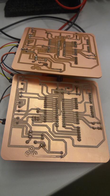
--- I designed the board one way, but I had PTH components, so I had to mirror the board making easier for soldering.
- Fabmodules - traces and cut files
| Part | Value | Device | Package | Description | MF | MPN | OC_FARNELL | OC_NEWARK | PROD_ID | VALUE |
| C1 | 100uF | CPOL-USE3.5-8 | E3,5-8 | POLARIZED CAPACITOR, American symbol | ||||||
| C4 | 100nF | CAPKIT | CAP-PTH-SMALL-KIT | Capacitor | ||||||
| C5 | 100nF | CAPKIT | CAP-PTH-SMALL-KIT | Capacitor | ||||||
| C7 | 22pF | 22PF-PTH-2.54MM-200V-5% | CAP-PTH-2.54 | 22pF ceramic capacitors | CAP-09128 | 22pF | ||||
| C8 | 22pF | 22PF-PTH-2.54MM-200V-5% | CAP-PTH-2.54 | 22pF ceramic capacitors | CAP-09128 | 22pF | ||||
| C9 | 100nF | CAPKIT | CAP-PTH-SMALL-KIT | Capacitor | ||||||
| IC2 | AVR-MEGA8-PPTH | AVR-MEGA8-PPTH | DIL28-3 | MICROCONTROLLER | ||||||
| IC4 | 7805T | 7805T | TO220H | Positive VOLTAGE REGULATOR | ||||||
| J1 | 455-1750-1-ND | CONN_03 | 1X03 | Multi connection point. Often used as Generic Header-pin footprint for 0.1 inch spaced/style header connections | XXX-00000 | 455-1750-1-ND | ||||
| JP3 | POWER_JACKPTH | POWER_JACKPTH | POWER_JACK_PTH | Power Jack | CONN-08197 | |||||
| LEDPWR | LED5MM | LED_5MM | LED (Generic) | |||||||
| R25 | RESISTORAXIAL-0.3-KIT | AXIAL-0.3-KIT | Generic Resistor Package | |||||||
| R27 | RESISTORAXIAL-0.3-KIT | AXIAL-0.3-KIT | Generic Resistor Package | |||||||
| RESET | TAC_SWITCHPTH | TACTILE-PTH | Momentary Switch | |||||||
| SV1 | FE06-1 | FE06 | FEMALE HEADER | unknown | unknown | |||||
| SV2 | FE06-1 | FE06 | FEMALE HEADER | unknown | unknown | |||||
| SV3 | FE06-1 | FE06 | FEMALE HEADER | unknown | unknown | |||||
| SV4 | FE06-1 | FE06 | FEMALE HEADER | unknown | unknown | |||||
| SV5 | FE06-1 | FE06 | FEMALE HEADER | unknown | unknown | |||||
| SV6 | FE06-1 | FE06 | FEMALE HEADER | unknown | unknown | |||||
| SV7 | FE06-1 | FE06 | FEMALE HEADER | unknown | unknown | |||||
| SV15 | MA03-2 | MA03-2 | PIN HEADER | unknown | unknown | |||||
| U$1 | FTDI-SMD-HEADER | FTDI-SMD-HEADER | 1X06SMD | |||||||
| X1 | MKDSN1,5/2-5,08 | MKDSN1,5/2-5,08 | MKDSN1,5/2-5,08 | MKDSN 1,5/ 2-5,08 Printklemme | ||||||
| X2 | MKDSN1,5/3-5,08 | MKDSN1,5/3-5,08 | MKDSN1,5/3-5,08 | MKDSN 1,5/ 3-5,08 Printklemme | ||||||
| X5 | MKDSN1,5/3-5,08 | MKDSN1,5/3-5,08 | MKDSN1,5/3-5,08 | MKDSN 1,5/ 3-5,08 Printklemme | ||||||
| X6 | MKDSN1,5/3-5,08 | MKDSN1,5/3-5,08 | MKDSN1,5/3-5,08 | MKDSN 1,5/ 3-5,08 Printklemme | ||||||
| XTAL | XTAL/S | QS | CRYSTAL |
- Extra LED;
- LM35 thermosensor.
This is a revisited assignment because the tasks weren't clear enough in my first attempt. I invited someone to discuss this issues, I asked Marco Mello to help me out. He's been my tutor for this week revisited assignment. We made a sketch of what would be networking applied with I2C protocol. The idea that came up was to have a inical read in a Master microcontroler and than, depending on the reading analysis, there would or not be a set of communication and instructions send to two slaves. One slave would control a led and another one would control a buzzer.
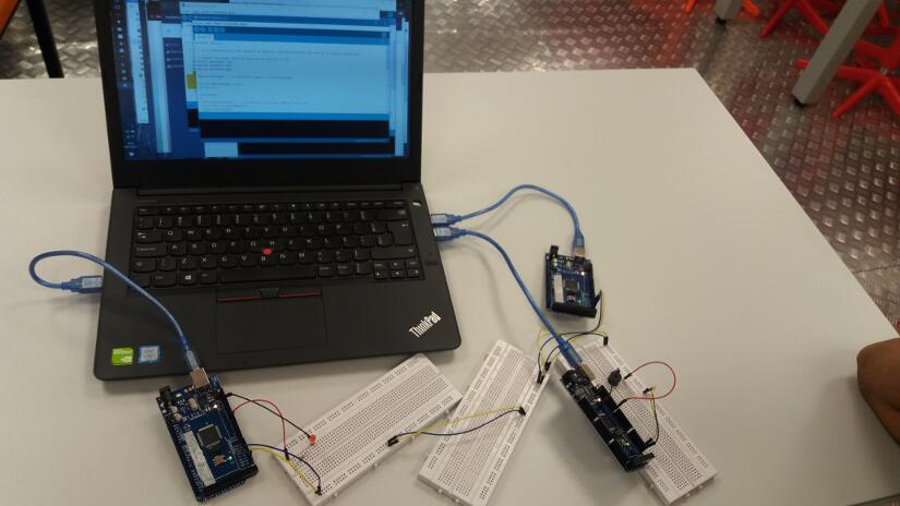
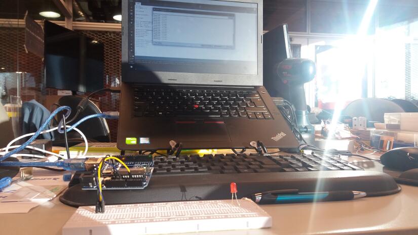
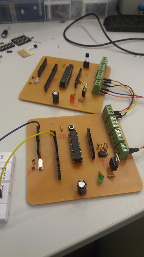
I chose to prototype the code with standard Arduino boards and protoboards. After that was ready, than a set of microcontrolers boards would be emmbeded with this code. As the assignment requests, the boards must be self made ones. As commented in previous assingments, the soldering material available burns SMD components pads. At the moment, and rush, PTH standard components were the best available choice. The boards are not so nice looking, they are bigger, but the principal is the same.
During inicial tests with Arduino boards, I made two short videos that show the importance of having the same referenc ground. You may see the command send being properly responded with same ground, but no response in different ground reference.
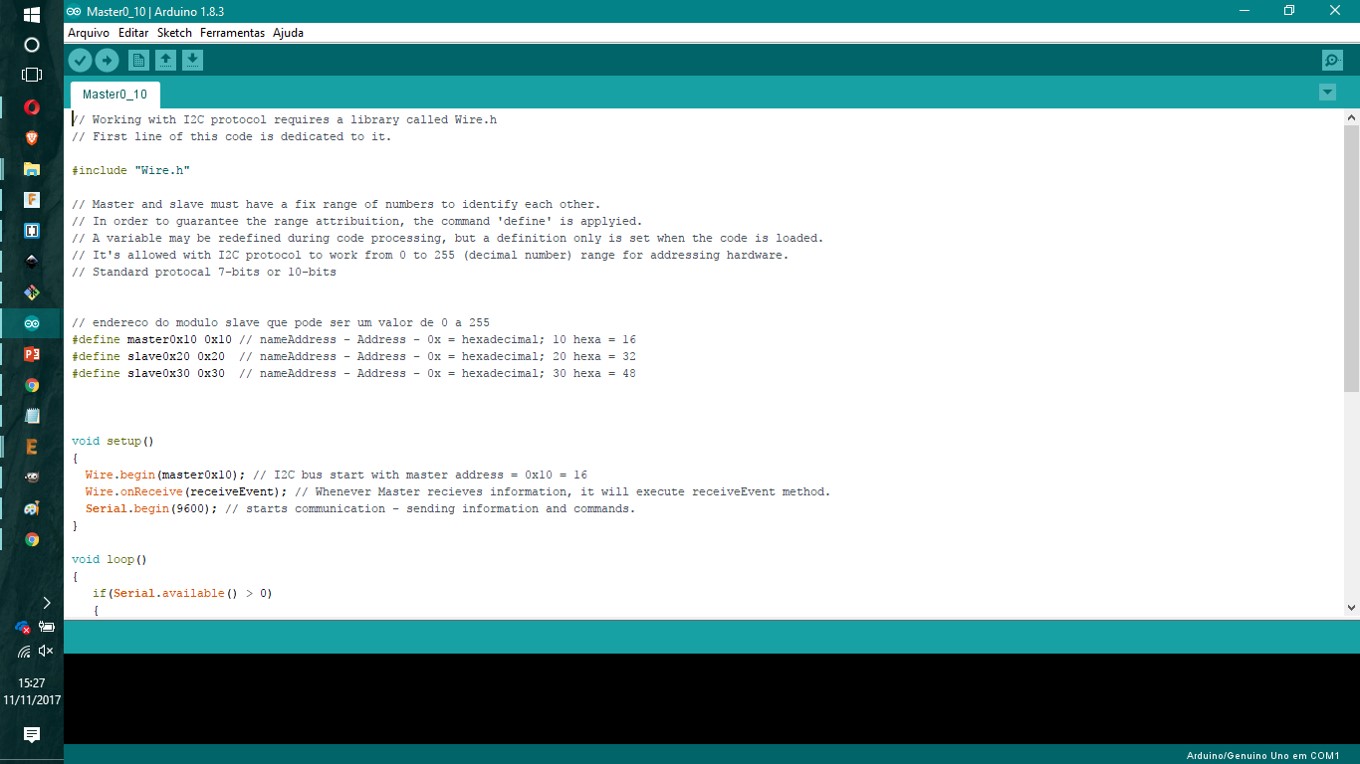
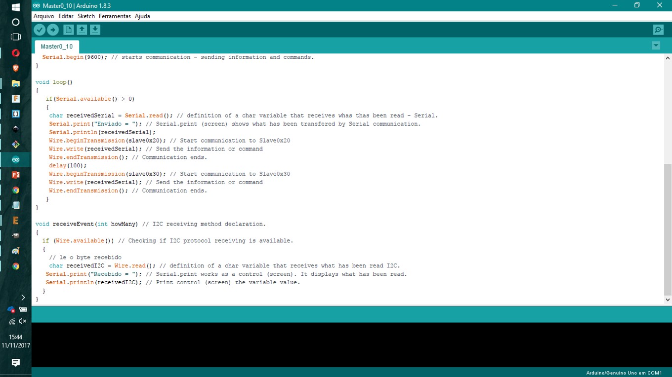
The code has comments. I explained why to chose definition of Master / Slave identification numbers; the communication and commands transfer with specific targets; begining and ending of each tranfer loop. The actuators are simple buzzer and led, but this code structure works regardless the actuator (it could be anything). The identification guarantees that each command goes to (or gets a response from) the specific microcontroler of interest inside the network.
An ATMega328P is the board microcontroler. It is too much for this application, but one may notice the board has all pins conect to headers. This idea is to build a flexible board that will be used in other applications as well. With time, different networking experiments can be tested with this board design.
It's been four days of building and testing boards. A late research on problems relates that flux for soldering might change material resistence over the board surface (if it is not really really clean). It is not enought to change a continuity multimeter test, but it ruins the board when power is turned on. I understand now many boards I built had problems because of flux use when soldering. Best explanetion.
The board I design has very thin traces. There were problems with that too. One board needed resoldering a few times. The borne that conected to DC power source wasn't properly solded and I had to repair during the tests. It also happend that the board led (power source) presented problems and stoped working.
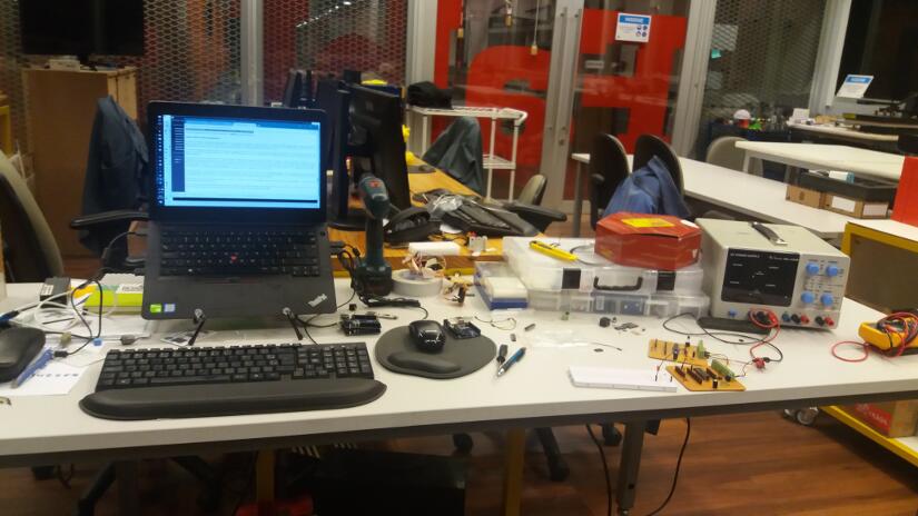
Fortunately, the main issues worked fine. My firt model of network was a prototype with three Arduino boards. As i couldn't build three boards on my on, I adapted the code to two boards only. The first round was a led sing information in a loop with a delay. So, Marster board would send a command to Slave board that would blink a led. This wasn't very interactive and the idea of implementing a thermosensor came up as a fast way to make two boards interacting with an input and a output integrated. The later version of codes, Master reads the temperature and over 28°C reading it sends Slave a command to turn on the led (and when temperature is above 28°C the command is to turn off the led).
The thermosensor is an LM35 and the exemple setup and code to work with it came from this Instructable tutorial. The first step was to try this setup with an Arduino board and a breadboard. I measured the temperature of the room (FabLab) and how easy it would raise when holded (finger pressed). Room temperature read avarage = 24,5°C and it was easy to raise it up to 28°C just holding a few moments.
Marco Mello, tutor for this week assingment - revisited - was able to help me debugging and also with the videos / documentation. I would like to say special thanks to him for his help.
Each board was tested with a blink standard example. After that, I modify the Master code and the Slave code. The first round is the Blink and the second round is the LM35 thermosensor. All Arduino codes can be download from this Arduino code folder.
Boards are not perfect, but they are functional for this tasks (I hope so).
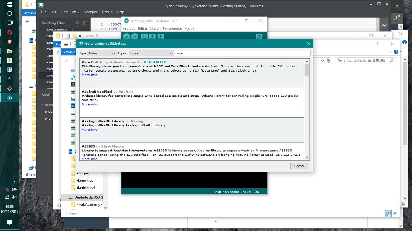
Observation: Arduino library MiniCore is needed to work with this microcontroler ATMega328.
- To download and install the library click here.
- Before uploading the code, there is the need to writhe Bootloader for each microcontroler unit, only after that the proper code can be transmited. I had an Arduino UNO as a tool to help me out preparing my boards microcontrolers. It is hand because it has the same socket as it runs ATMega328.
- Datasheet here ATMega328.
-----------

This work is licensed under a Creative Commons Attribution-ShareAlike 4.0 International License.