- Design and build a wired &/or wireless network connecting at least two processors.
Class material: Networking and Communications
Insper FabLab's operational manual here.
Roland MDX-40A - Machine's tutorial, please click here.
One may also check this tutorial explaining how to mill a coin (and how to operate and setup the working material in a machine like Roland MDX-40A). The manufacture link to its own documentation and information will be found here.
- Autodesk EAGLE
- GIMP2.0
- Roland VPanel for MDX-40A
- Fab Modules
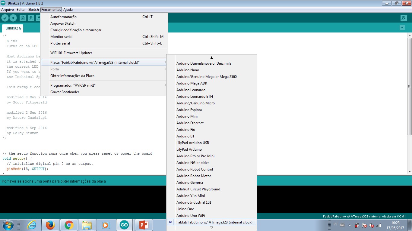
- Arduino IDE
- MS Paint (for PNG images editing)
- FabKit 03 - schematic.
- FabKit 03 - board.
- FabKit 04 - schematic.
- FabKit 04 - board.
- Thermo sensor - schematic.
- Thermo sensor - board.
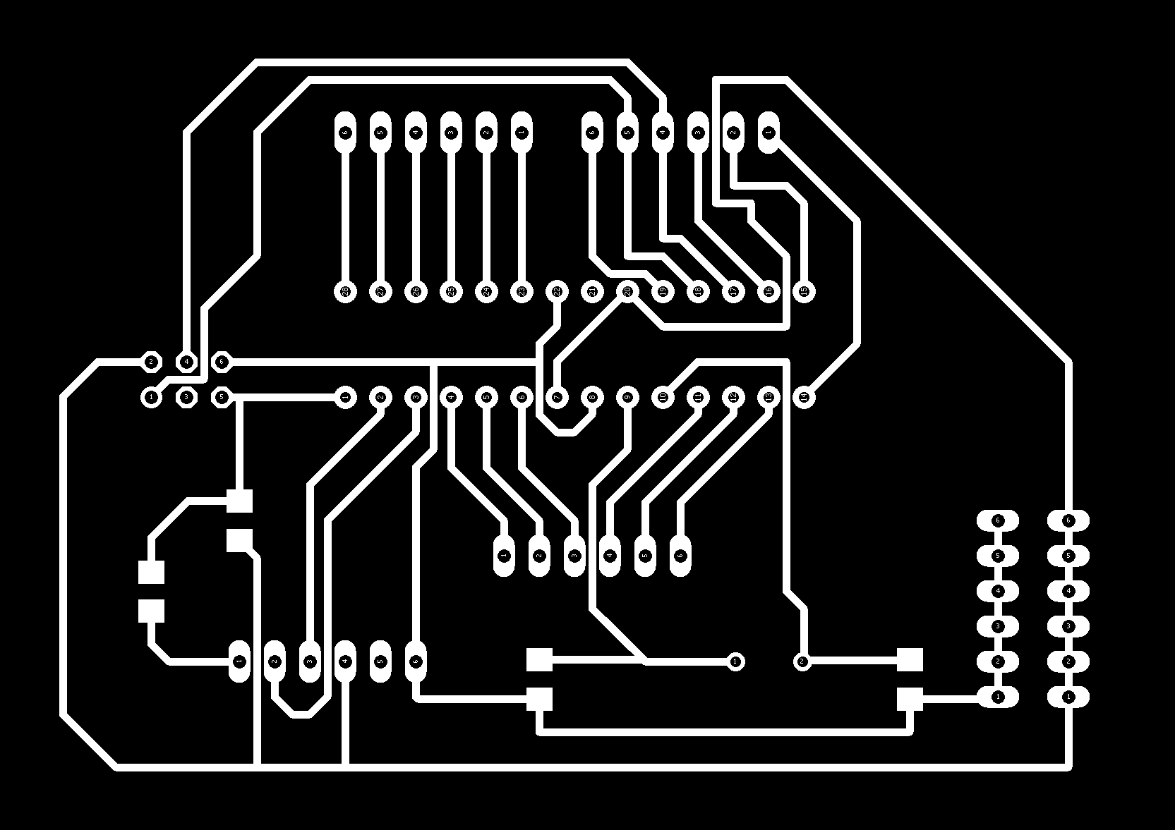
- Microcontroler final edition - schematic.
- Microcontroler final edition - board.
- Microcontroler PNG image - traces.
- Microcontroler PNG image - cut.
- Extra information and/or files about FabKit 0.3-0.4, please click here.
- SparkFun Ealge libraries.
- Adafruit Eagle libraries.
- Microcontroler traces - rml.
- Microcontroler cut - rml.
- Thermosensor traces - rml.
- Thermosensor cut - rml.
Relay actuator.
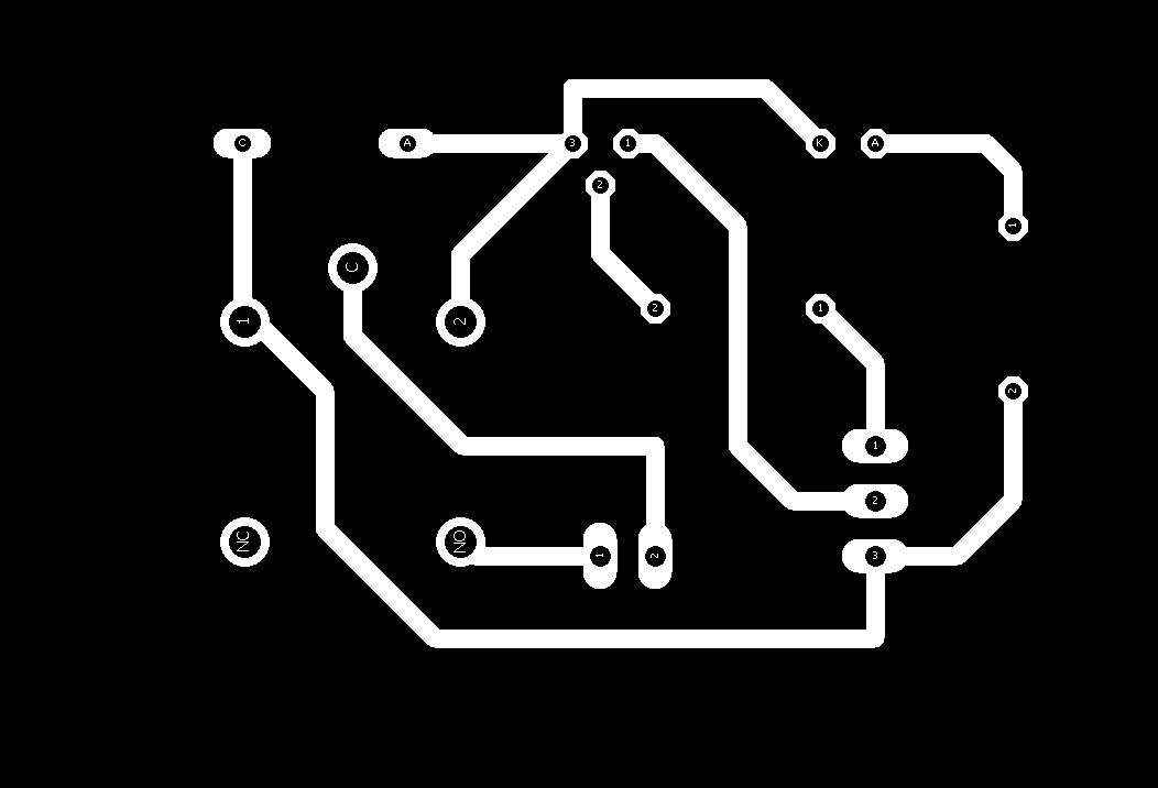
- Relay final edition - schematic.
- Relay final edition - board.
- Relay PNG image - traces.
- Relay PNG image - cut.
- Relay traces - rml.
- Relay cut - rml.
This assignment was complete together with the final project. For the coffee maker I had to integrate input from a temperature sensor (in this case it has a microcontroler attached), a keyboard (only buttons), an output to a display LCD16x2 with an adaptor to serial comunication and a relay 10A/220V actuator. I made a microcontroler board to integrate the system.
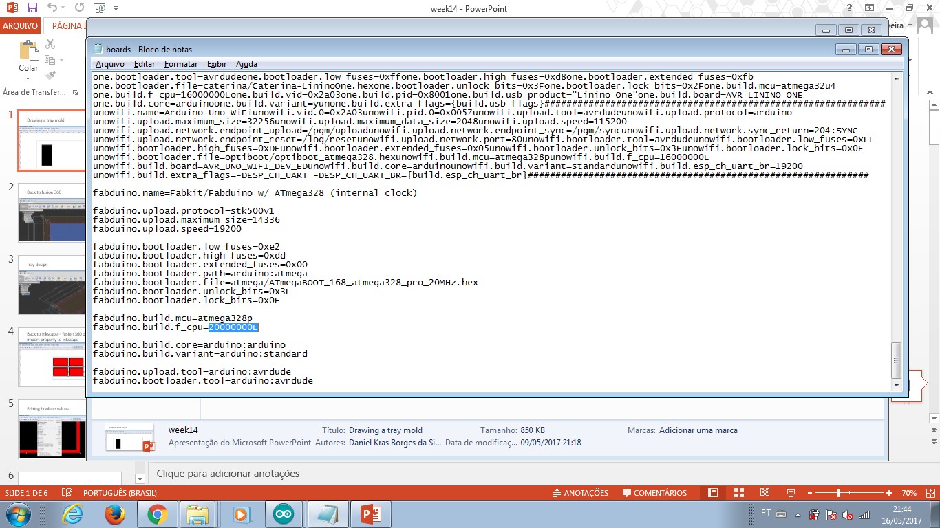
The first idea was to work with FabKit03/04 microcontroler boards. It took me four weeks to work with the board experiencing bad news and trouble. A more detailed check helped me realize the soldering was happening in a too high temperature. During the input device week assignment, I lost a good thermosensor because of that. Since then, I started to sold parts in a lower temperature (less than 280 degrees Celsius).
For the microcontroler board, I chose PTH component. The same microcontroler AtMega328 - but in a different size - worked fine with my new board. I could integrate all systems. You will find more documentation about it in the final project webpage.
I also made output devices assignment with a I2C LCD display and an Arduino board. This would also verify the condition of two microcontrolers in a network I have designed. For this documentation, please refer to exercise03 webpage.
The code that integrates all functions together (as a network) is the final project Arduino IDE standard code. You will it find at the link below with extra files and documents.
The Arduino code has a best practices standard that starts with libraries declaration, than variables, than a void setup (it is a map of what is going to work and what is attibuted to each pin in the code) and than a void loop (which is the set of main activities or processes the code executes). The loop includes everything that must be checked each programm cycle It is a set of methods. After the loop is defined, it follows a sequence of methods 'sub-codes'.
There is a method that reads temperature. There is another method that controls the heat actuator. A third methot relates this information and respond.
Programm workflow and microcontroled boards interactions:
- LCD message do user: stand by mode
--- heat actuator OFF
- Keyboard activated - recieve user command at any time.
--- Keyboard is controled by a microcontroler board - mainboard.
- Temperature control - after cycling keyboard read method, the thermocouple sensor communicates to mainboard and sends its temperature measurement.
- Mainboard checks temperature with programming conditions.
--- Each method has different conditions.
--- Conditions analysis sets the heat actuator ON or OFF.
- Mainboard sets heat actuator ON of OFF
- Mainboard transmits message for user to LCD board
- LCD board displays message for user and check if there is another message arriving.
- Stafety: Turn OFF method garantees the heat actuator doesn't get and endless loop increasing temperature.
ArduinoIDE code: click here.
In other words
I defined how the main controler board interacts with each other part of the system and in what sequence it has to happend in order to garantee the goal results. Adjustments in the system are done by measuring time. As the coffee maker has heat as a critical thing, the timing of measuring temperature and reacting to it is important. Also, as the heat can cause damage and burn someone or something in its sorroundings, turn off after a while is an important implementation to code.
The system permits 03 different modes. These modes are related to time, time dependent, and it means different amount of coffee can be made. This integration indicates a system that interacts with users - there is a selection keyboard and a display with feedback messages.
small.jpg)
small.jpg)
small.jpg)
small.jpg)
-----------

This work is licensed under a Creative Commons Attribution-ShareAlike 4.0 International License.