
- Design a 3D mould, machine it, and cast parts from it.
Class material: Molding and Casting
Insper FabLab's operational manual here.
Roland MDX-40A - Machine's tutorial, please click here.
One may also check this tutorial explaining how to mill a coin (and how to operate and setup the working material in a machine like Roland MDX-40A). The manufacture link to its own documentation and information will be found here.
Laboratory scale - any standard model like this will help.
- Ferris Wax Block 1lb, Green, 6" X 3.5" X 1.5".
- Mill - endmill - 2,00 mm cut diameter - 02 flutes - example here.
- Wood stick - extra help supporting silicone mold.
- Tape - extra help to fix wood sticks.
- Silicone rubber - Avipol manufacture - It worked fine.
- Silicone rubber - Redelease manufacture - It worked fine also.
- Silicone dye - Avipol manufacture
- Gloves
- Autodesk Fusion 360
- Inkscape
- GIMP2.0
- Roland VPanel for MDX-40A
- Fab Modules
CNC is a technology that allows one to produce code and with it 'tells' a machine what to do in any given point inside its working area. The CAD tool works with desing, or the initial creative step of any project. After that, when there is the need to manufacture it - and therefore CNC technology is demmanded - another kind of software is needed: CAM is the software that creates the machine program from a digital design. During FabAcademy, most of my projects will be developed in Fusion360 CAD tool or Eagle 8.0 schematic/board tool and, from there, Fabmodules will be the next step as CAM tool.
This week assignment is casting something from a mold. The shape developed for this exercise was made with Fusion360. The 'CAM code' (in our case Roland MDX-40A is rml code) is the software created with Fabmodules that specifies the toolpahts for the milling machine to remove or cut the material in the way it was designed for getting the user a result. In this week case, the result is a mold.
So, the steps are:
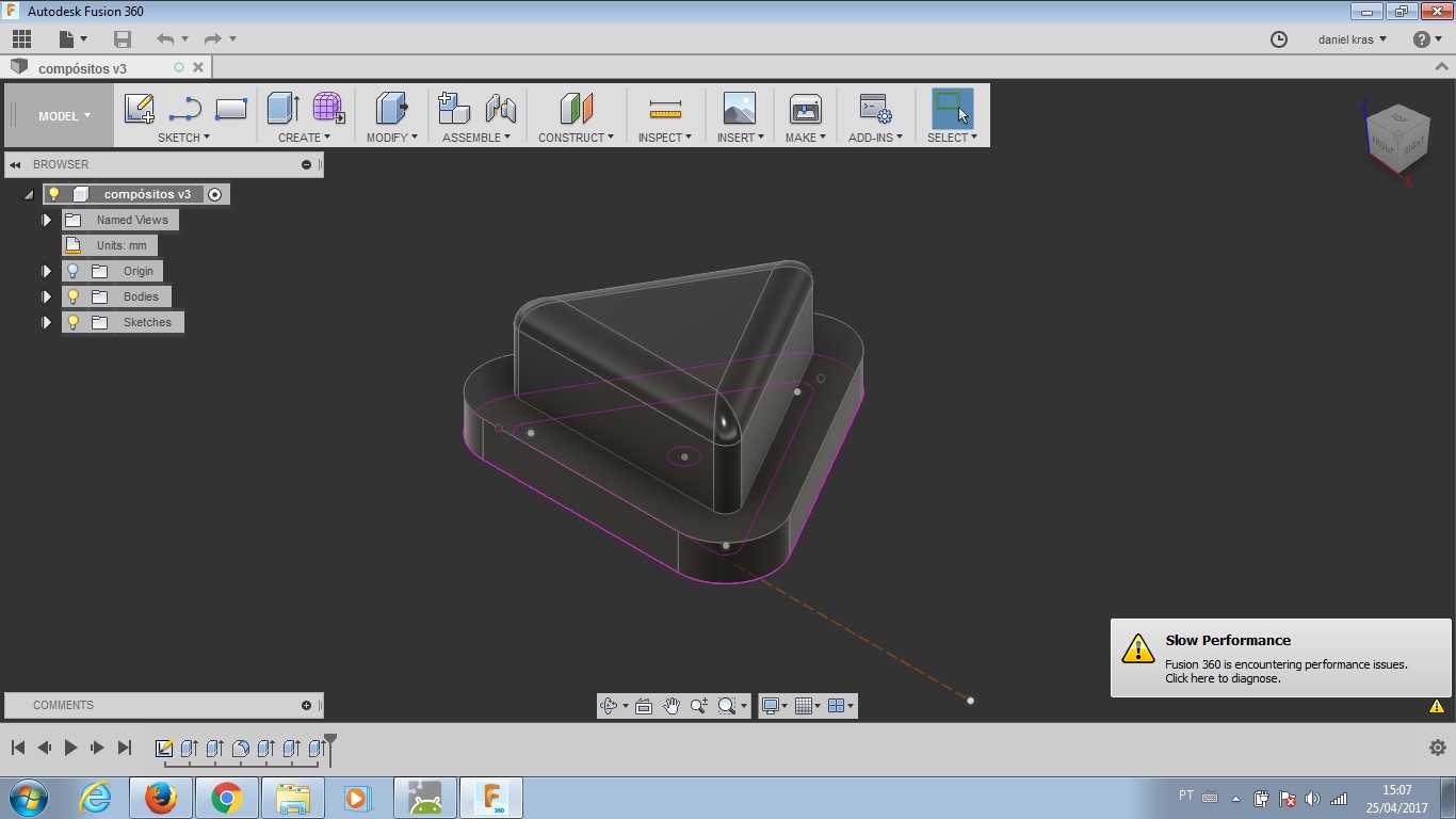
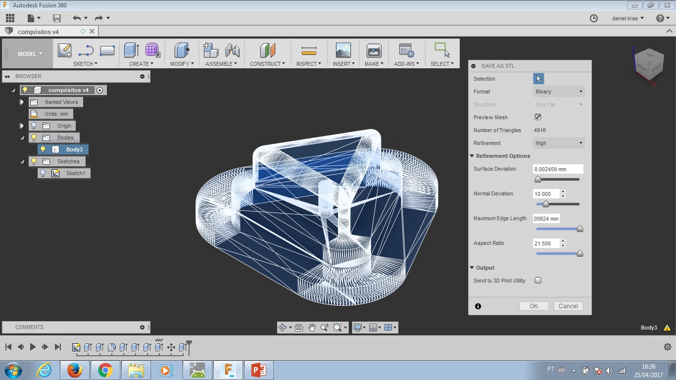
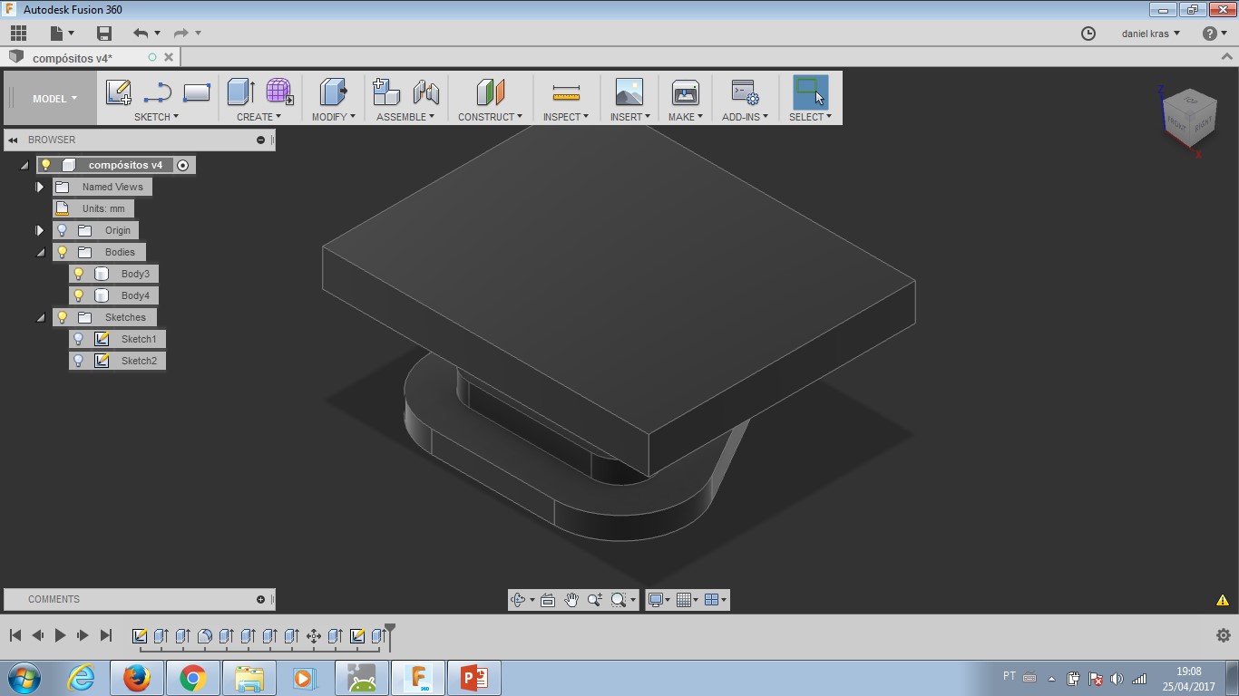
- Design a 3D object. Extra Fusion360 project files: here.
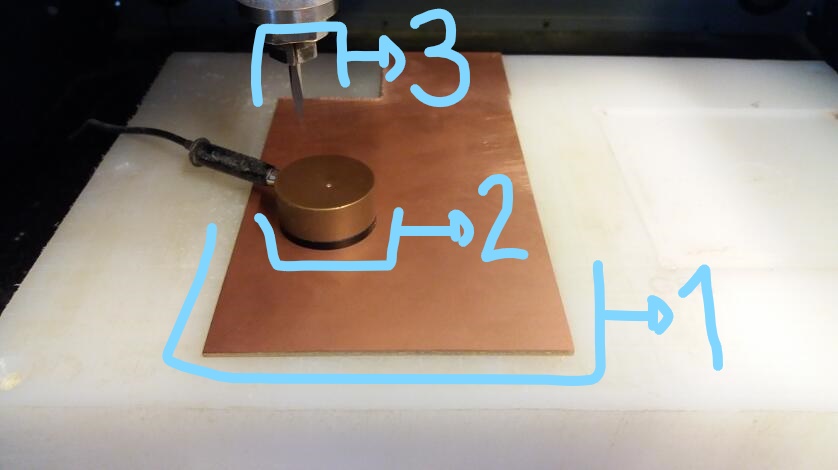
- Produce a counter-mold - Milling operation.
- Produce a mold - casting operation.
- Produce the 3D object - second casting operation.
I will put here the standard setup for the machine and tools we have here at Insper for FabModules - 3 axis milling.
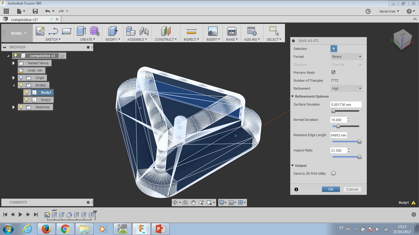
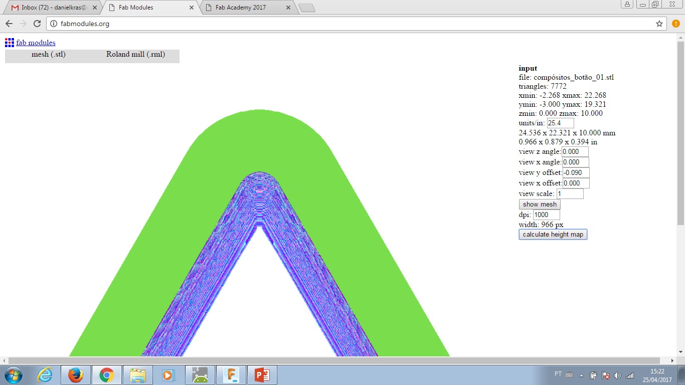
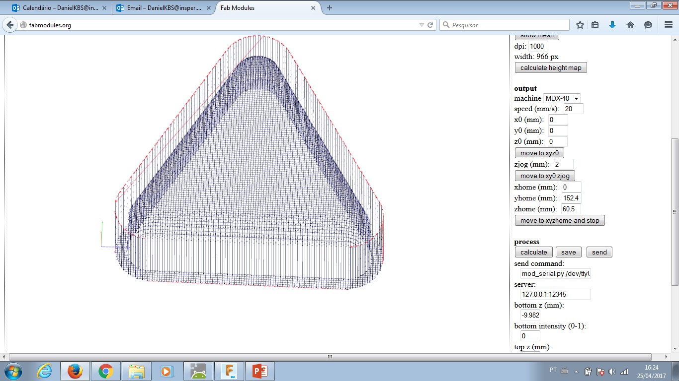
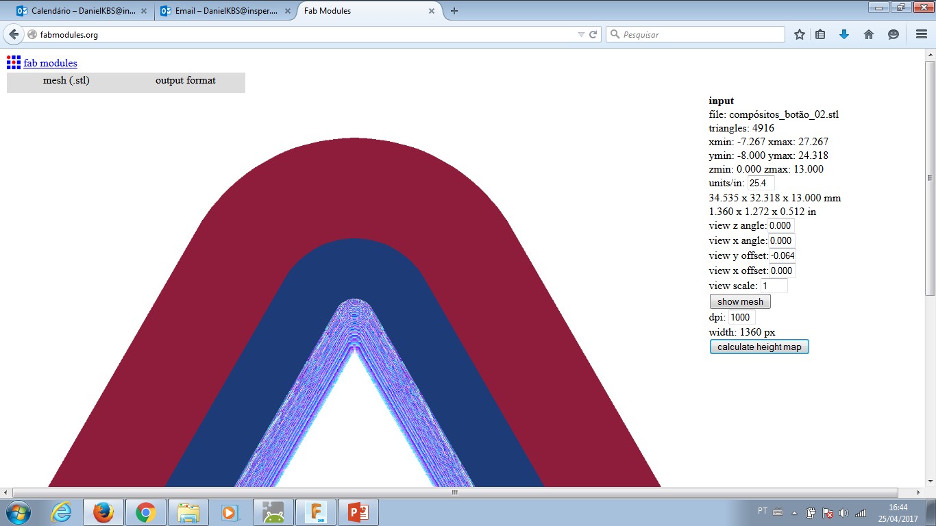
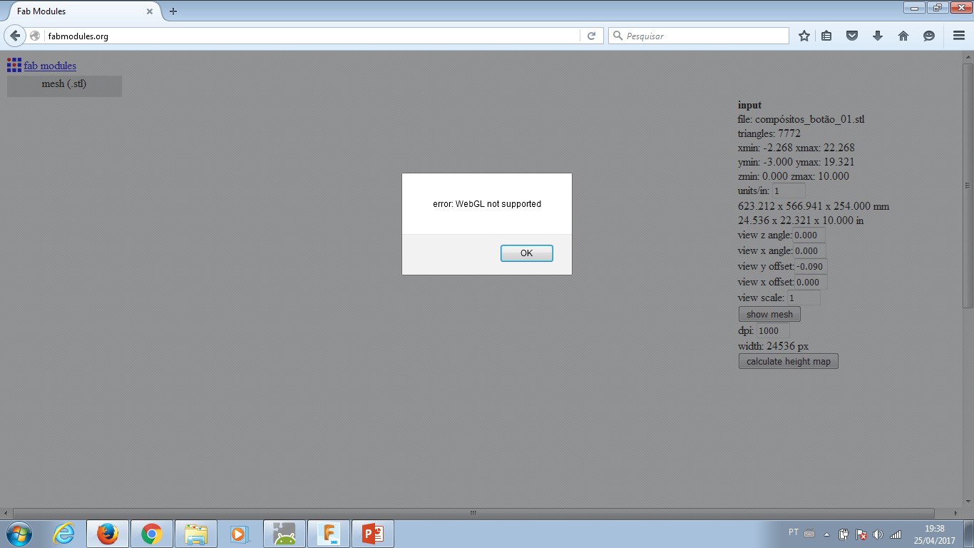
Input: Mesh (.stl) - this is an object file STL that will describe shape toolpath has to achieve when finishing the mill operation. Select the object you need.
--- Object will be displayed in screen.
--- Fill in the right menu: Units/in. = 25.4 as I design with a metric system.
--- Click the right menu: calculate height map - this will turn each different height in a colour layer. These layers are gonna provide input to CAM and generate .rml machine code.
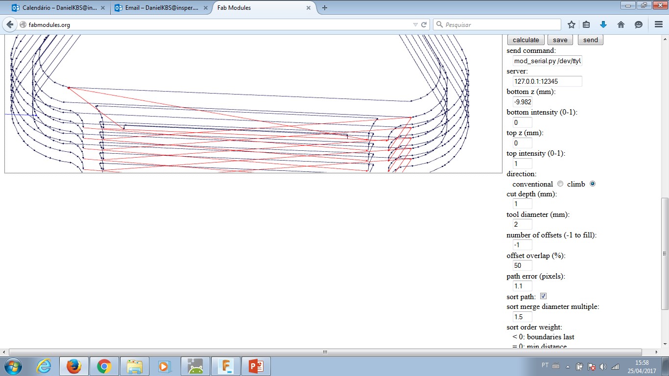
Output format: Roland Mill (.rml) - this selection will set the FabMoludes to work with a milling machine.
Process: if the selected option is 'wax rough cut' than
--- Machine = Roland MDX-40A
--- x0 (mm) = 0
--- y0 (mm) = 0
--- cut depth (mm) = 1.00
--- tool diameter (mm) = 2.00
--- number of offsets = -1
--- offset overlap (%): 50
Process: if the selected option is 'wax finishing cut' than
--- Machine = Roland MDX-40A
--- x0 (mm) = 0
--- y0 (mm) = 0
--- cut depth (mm) = not needed
--- tool diameter (mm) = 2.00
--- number of offsets = 1
--- offset overlap (%): 90
You may adjust the setup once you have different milling tools. As the phenolite paper changes from batch to batch, there is the need to compensate ondulations and assimetry eventualy.
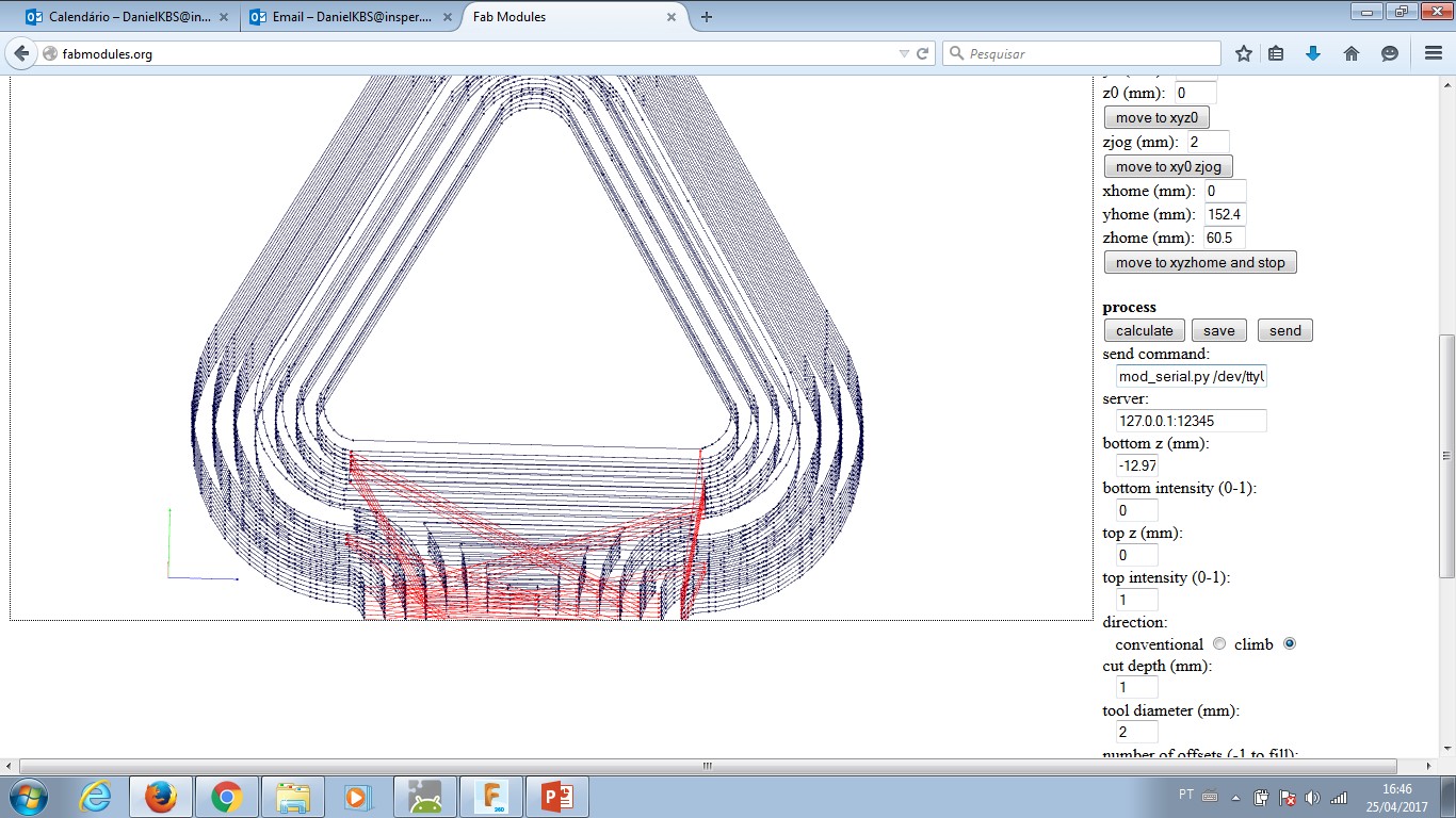
PRESS: "Calculate" button to check how the simulation goes on your computer. Observe if the mill process remove material where it is supposed to and leave material untouched the same way.
PRESS: "save" button in order to have the rml file in your computer.
FabModules allows its user to make other specifications and different setups. I only made reference to the ones needed for PCB milling. Anyother setup may be left the way it comes preseted.
Once the rml program is done, there is the need to move from computer setups to machine operation. Roland's Vpanel program is part of machine's manual (click here); some extra information is displayed below.
The machine needs to be power on in order to comunicate with Vpanel software.It follows some images of Vpanel Operation to config a new job.


Fusion360 design file Mould project.
Mold is to create a form that gives one the possibility to replicate objects. The mold is a 'negative' form for this to work out properly. Casting is the process of replication through materials that are liquid in on state and get solid inside a mold. After ejecting the material from the mold there is a replica.
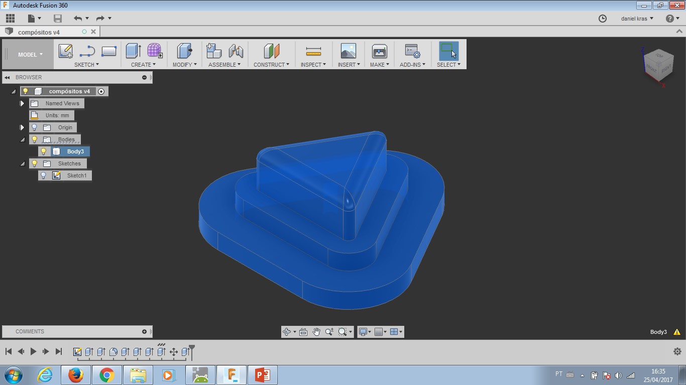
To build a button was the choice for this week assignment. There will be the need of a button in my final project (I think...). As a coffee maker has temperature, time and mode as possible controls, I decided to shape the button as a triangle. This shape for controls 'up' and 'down' and also 'play' and 'fast forward'. So, it seemed a good shape to work with.
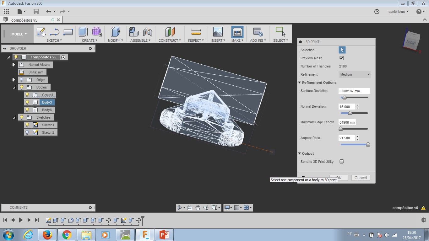
I did the design with Fusion360 and then made a gcode with FabModules. After the first milling completed, I wanted to redesign the shape and mill it again. That was not possible. FabModules stoped working for 3D processing in my computer. I tried diferent browsers (Opera, Chrome, Mozzila and IExplorer) without any success. My tutor Kenzo is discussing this error with other tutors from the FabLab network.
Working with the piece I got - wax milled counter-mold - I made a silicon (blue) mold. From that, I was able to reproduce the shape a few times. Pictures below will tell more.
small.jpg)
small.jpg)
small.jpg)
small.jpg)
small.jpg)
small.jpg)
small.jpg)
small.jpg)
The object mold (blue rubber silicone) was good. I understand the result was nice. In order to get a good moisture, there was the need of a scale. 1.0 part of rubber to 1/40 parts of catalizer. Small variance wasn't perceptive, but when I tried to mix both parts without a scale (under my instincts orientation) it didn't work. I have the same results from other students.
To make resin objects, I had some help of a shaking surface (which is any rotating machine with a layer to leave the mold casting itsef). Even thoght, the time to dry was too short and quite many bubbles were inside the object. The las experiment (images above - middle) shows a better result with a standard resin.
For this assignment, I try to experiment with different colours and didn't approach bubbles as a main issue. This is going to be develop in further experiments.
-----------

This work is licensed under a Creative Commons Attribution-ShareAlike 4.0 International License.