
- Make an in-circuit programmer by milling the PCB (program it, so that you can use it to program your board in Electronics Design week, and in other weeks)
Class material: Electronics Production
Insper FabLab's operational manual here.
Roland MDX-40A - Machine's tutorial, please click here.
One may also check this tutorial explaining how to mill a coin (and how to operate and setup the working material in a machine like Roland MDX-40A). The manufacture link to its own documentation and information will be found here.
Phenolic paper - copper layer for circuit boards - standard 1,7 mm thickness - example here.
Mill - engraver - 20°edge - example here.
Mill - endmill - 2,00 mm cut diameter - 02 flutes - example here.
Brian's project BOM:
- 1x ATtiny45 or ATtiny85;
- 2x 1kΩ resistors;
- 2x 499Ω resistors;
- 2x 49Ω resistors;
- 2x 3.3v zener diodes;
- 1x red LED;
- 1x green LED;
- 1x 100nF capacitor;
- 1x 2x3 pin header.
This week assignment was based on a project. Brian is the author and the link to his project page is here. The board documentation is very good! And gives more information about it.
At this moment I still don't have much experience with solding components, but I had some experience in the past. It wasn't so hard to re-start. I kept the impression to sold is about controling the way you breath.
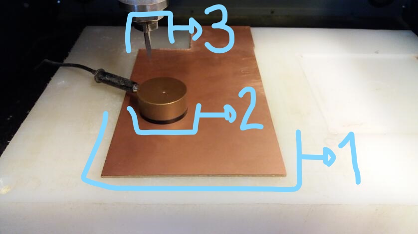
Preparing the plate with a milling machine was easier. It has been a while since I first start operating milling machines. I understand the process better. Fab Modules was new in it and I really liked.
My last opportunity to operate a milling machine was january 2017 when we add furniture to our Fab Lab (with an OpenDesk website project). ShopBot was the machine and VCarv the gcode generator.
The first solding attempt faild and I had at that point only one PCB board cut. Soon I cut other three units. The tool we had in the lab was a vcut 20° with and edge of 0,1 mm. The result was nice, but my local tutor already said I may expect some complains about this tool change. It was a situation I had to adapt.
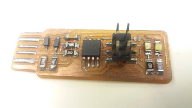
After having the plate done, I did the picking for eletronic components. Later, I found out there was one resistor I miss read (two units) and, because of that, the success and happiness of pluging it on and seing the leds bright just vanished.
Tomorrow I will have another chance to re-sold components and test my PCB board again.
When programming the board I faced two major problems. The first one was connection. I had to cut the edge of the board - USB connection / short cut to computer pads - to make it really connect to a computer. The second was about the software to program the board as a programmer. Our tutor Kenzo provided us with a Linux notebook and it was very handy. Through the Linux notebook I was able to programm the board and succed in using it later (mostly with the display setup tests).
The issue about Linux and Windows was that this USBtinyISP has no cristal neither resonator. It had to sincronyse with the computer USB port in order to run the code. This code will program the microcontroler to be a programer only. For this to happen there are two steps: first to program the microcontroler; second to turn the microcontroler a not programable board anymore. This second step is achieved by removing a sold bubble (short circuit) placed in the circuit board. After this material is removed, the board circuit is open in a way its microcontroler is not able to chance the recorded program.
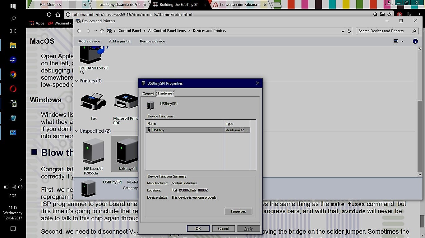
After I tried to work with Windows10 in my notebook and failed, I swiched to Linux in an old notebook Kenzo provided us. The driver worked - meaning I could program my USBTinyISP. Later, I conected my device to my Windows10 notebook again. I had to search for this device from control panel and check if it was runing properly. It was and I made some programing on my hello board with it (after I build the hello board).
At the end, the way to programm the USBtinyISP was to follow Brian's webpage tutorial. I remember that Kenzo helped me out with that once we were with Brian's text in his computer and I was runing the programmer software in the Linux notebook.
The link to Adafruit drivers is here. The webpage gives a step-by-step guide to install the drivers and also points changes that are needed for Linux and Mac users. Click here to get information for the Linux - AVRDUDE programmer. Another step-by-step - how to install AVR dev tools link to Ubuntu will be found here. I also added to this documentation instalations files: AdaFruit drivers.exe and AVRDude compact file 5.3.1.
At last, the documentation in our class page (this link) has instructions to make the programming and tests with the USBTinyISP. I would like to remember that an extra USB cable is suggested as a standard procedure for safety (of the programmer device and USB port of the computer). I run the instructio with my tutor helping me out and It worked. There is an image with the programmer linked to my notebook at the end of this webpage.
CNC is a technology that allows one to produce code and with it 'tells' a machine what to do in any given point inside its working area. The CAD tool works with desing, or the initial creative step of any project. After that, when there is the need to manufacture it - and therefore CNC technology is demmanded - another kind of software is needed: CAM is the software that creates the machine program from a digital design. During FabAcademy, most of my projects will be developed in Fusion360 CAD tool or Eagle 8.0 schematic/board tool and, from there, Fabmodules will be the next step as CAM tool.
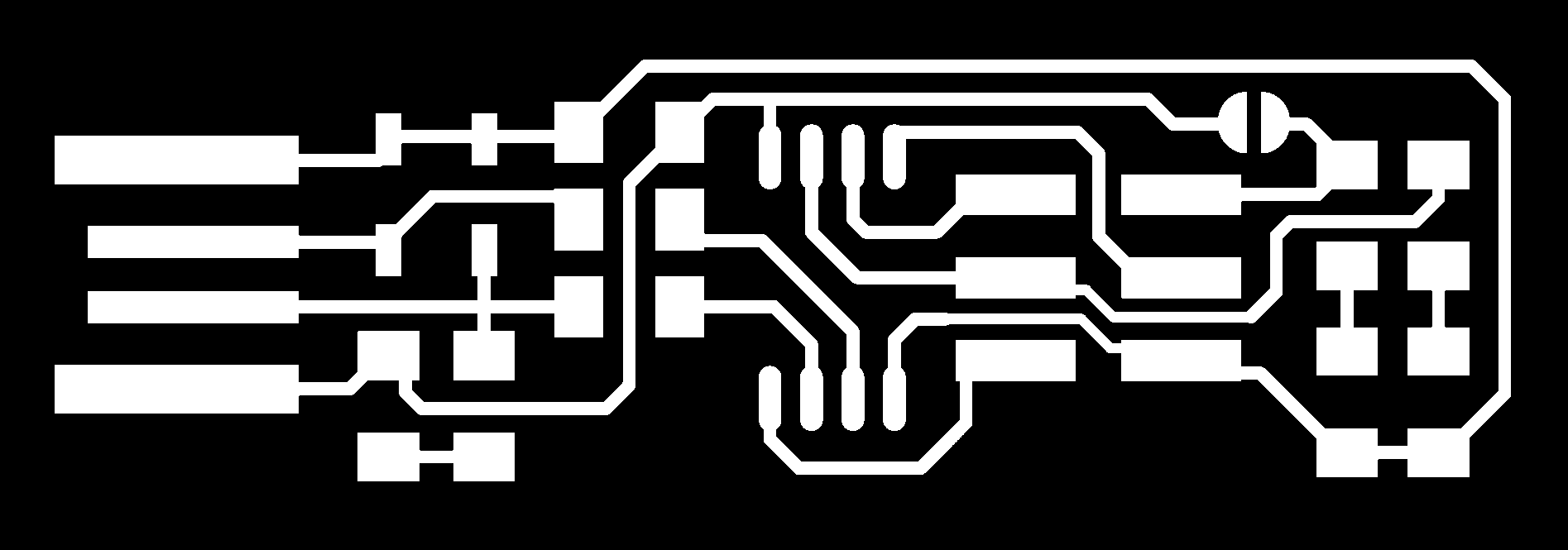
This week assignment is a PCB that is already designed. That means the components are already displayed in board conected to each other respecting the eletronic needs of energy and logic. For these components communicate to each other tracks must be placed in the board. The 'CAM code' (in our case Roland MDX-40A is rml code) is the software created with Fabmodules that specifies the toolpahts for the milling machine to remove or cut the material in the way it was designed for getting the user a result. In this week case, the result is a PCB.
As there will be more than one oportunity to mill PCB during FabAcademy, I will put here the standard setup for the machine and tools we have here at Insper for FabModules.
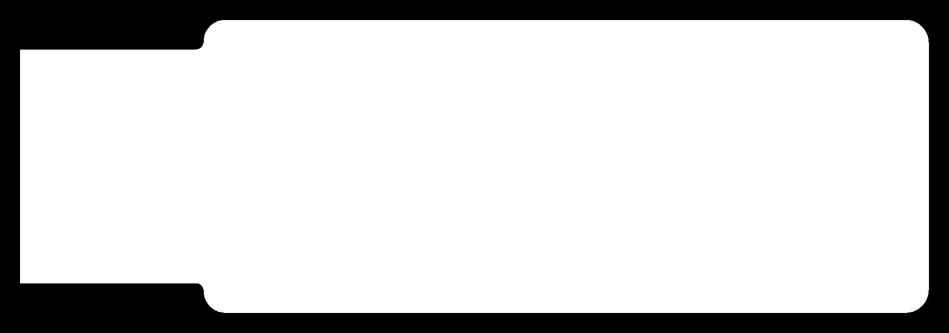
Input: this is an image file png that will describe the traces or cut need on the board. Select the image you need for each PCB. This exercise has this suggested board traces and this suggested board outline.
Output format: Roland Mill (.rml) - this selection will set the FabMoludes to work with a milling machine.
Process: if the selected option is 'PCB traces' than
--- Machine = Roland MDX-40A
--- x0 (mm) = 0
--- y0 (mm) = 0
--- cut depth (mm) = 0.2
--- tool diameter (mm) = 0.11
--- number of offsets = 8
--- offset overlap (%): 50
Process: if the selected option is 'PCB outline' than
--- Machine = Roland MDX-40A
--- x0 (mm) = 0
--- y0 (mm) = 0
--- cut depth (mm) = 0.2
--- stock thickness (mm) = 1.7
--- tool diameter (mm) = 2.00
--- number of offsets = 1
You may adjust the setup once you have different milling tools. As the phenolite paper changes from batch to batch, there is the need to compensate ondulations and assimetry eventualy.
PRESS: "Calculate" button to check how the simulation goes on your computer. Observe if the mill process remove material where it is supposed to and leave material untouched the same way.
PRESS: "save" button in order to have the rml file in your computer.
FabModules allows its user to make other specifications and different setups. I only made reference to the ones needed for PCB milling. Anyother setup may be left the way it comes preseted.
Once the rml program is done, there is the need to move from computer setups to machine operation. Roland's Vpanel program is part of machine's manual (click here); some extra information is displayed below.
The machine needs to be power on in order to comunicate with Vpanel software.It follows some images of Vpanel Operation to config a new job.


small.bmp)
small.bmp)
small.bmp)
small.bmp)
small.bmp)
small.bmp)
small.bmp)
small.bmp)
small.bmp)
small.bmp)
small.bmp)
-----------

This work is licensed under a Creative Commons Attribution-ShareAlike 4.0 International License.