1. Board design and fabrication
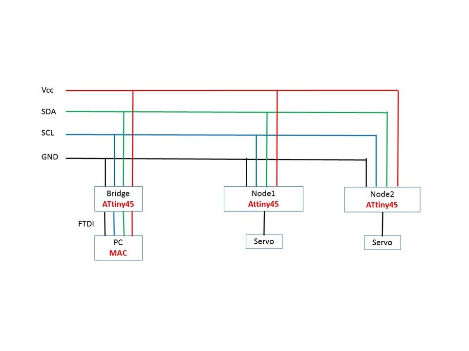
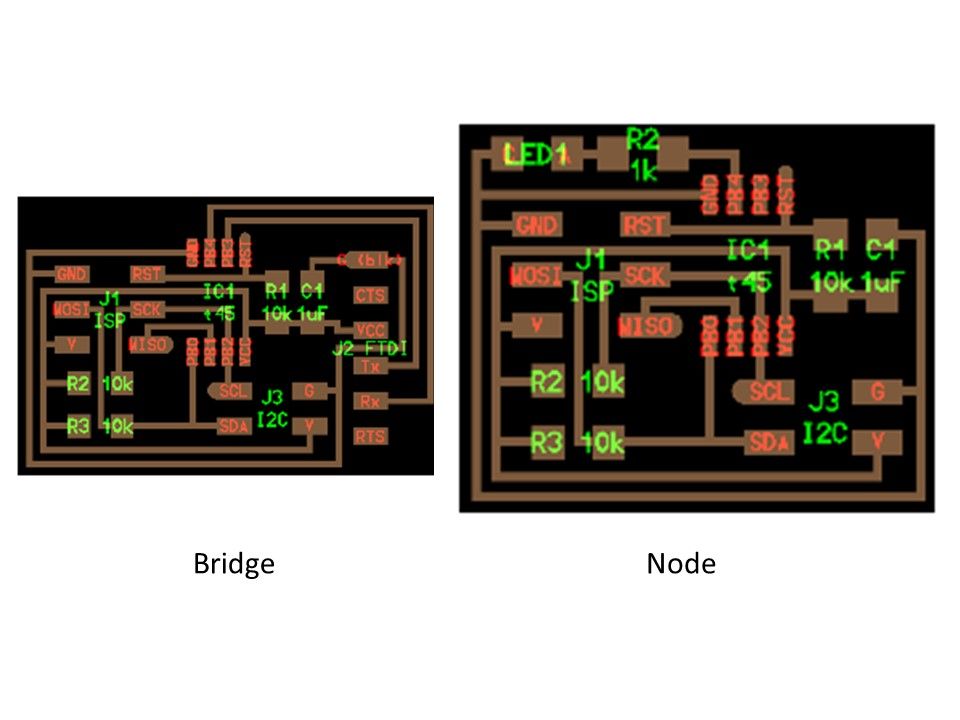
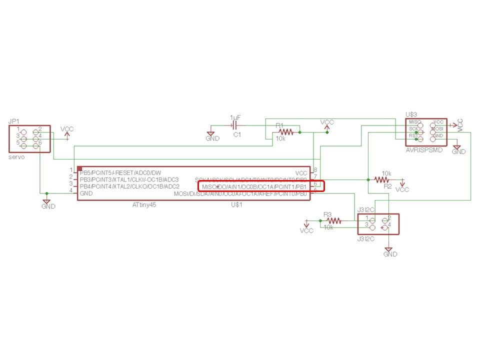
I examined the communication method. I decided to connect with I2C method. I referred to the sample board.
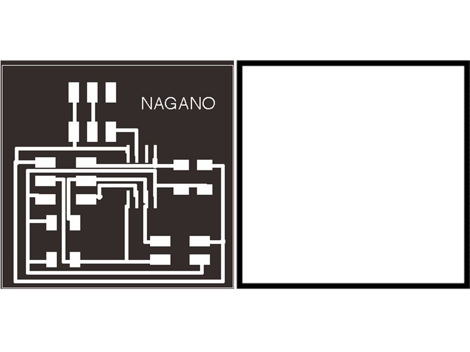
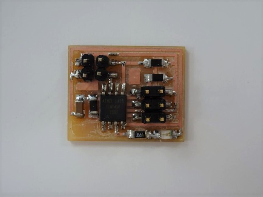
Since the board of Bridge has no circuit-like change, it was used in the circuit as it was. The board of Node considered the final project and changed from LED to servo motor. Cutting data was prepared as shown in the figure.
2. Board preparation
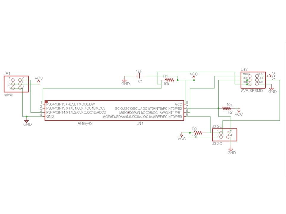
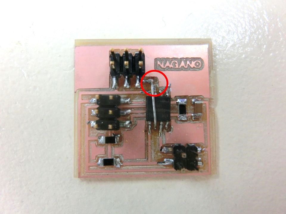
I put a boat loader on each board and succeeded. Next I wrote the servo program on Bridge's board. But it did not work. I confirmed the ATtiny 45 pin and found that the PWM signal for servo control must be connected to pin 6. Since the pattern could not be connected, it was connected with a jumper wire.
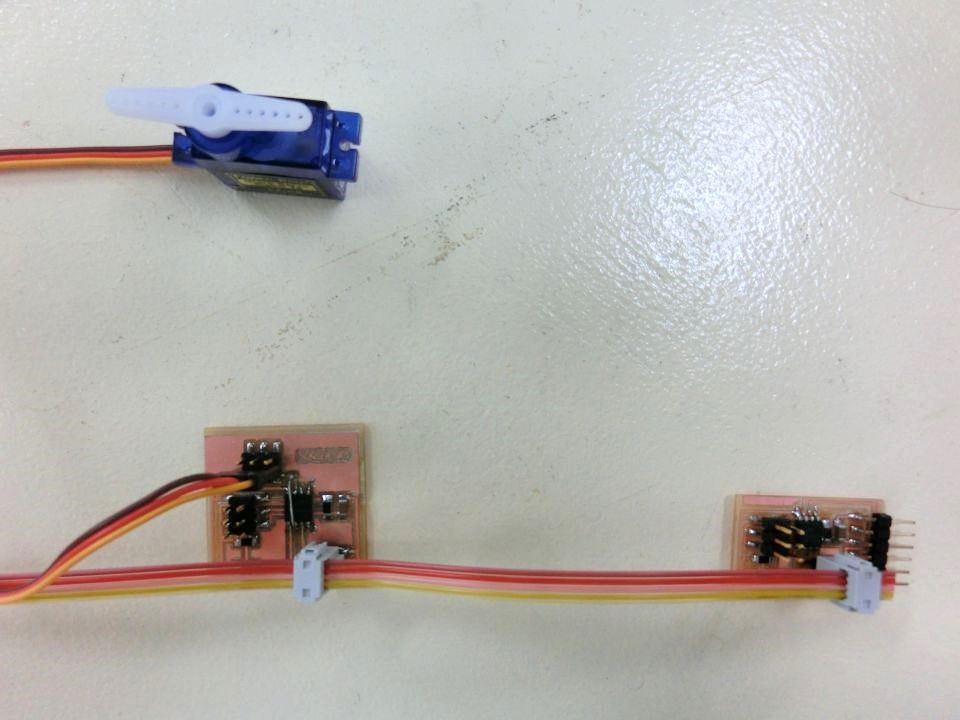
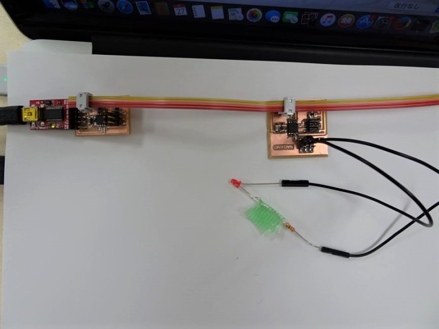
I wrote the program used during production of the output board. I was able to confirm that it works like a video.
I also made a board for LEDs to confirm the second connection. I could confirm that I write a blinking program of LED for operation confirmation.
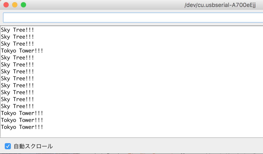
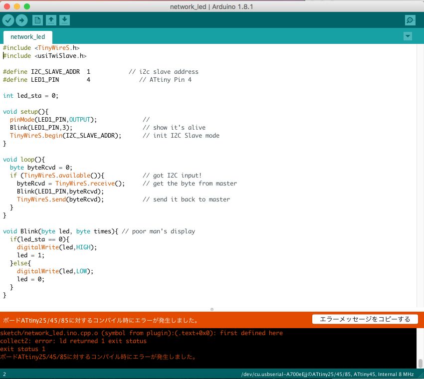
As a result of the execution, it was confirmed that the character returned on the master side. However, the slave side could not write sketches due to compilation error. Onodera's page did not confirm the correspondence of the error.
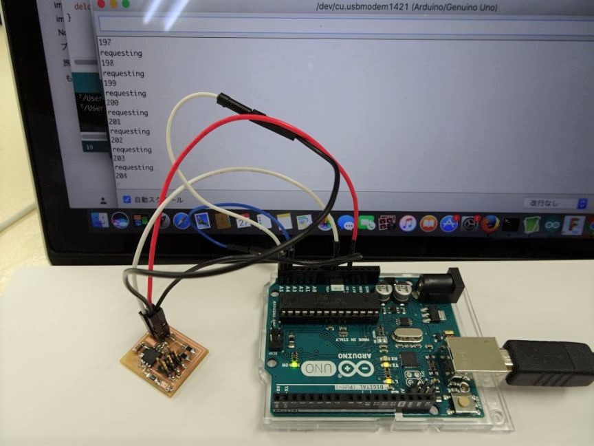
On this page, I used Arudino UNO as a master. Similarly, I wrote a sketch on the master side using Arudino UNO. On the slave side, the LED flashes when communication is sent. By referring to the above page, the number of data reply counts is also counted.
master for Arudino UNO
slave for ATtiny45
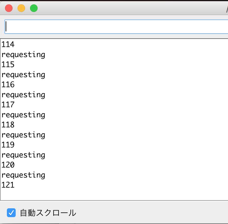
I could communicate like the video below, and it was confirmed that the number of data transmission has been counted up. When connected to the slave side and executed it, it was confirmed that the LED flashes with count up of data transmission like video. I also tried a servo board, but it did not work. I can not analyze the cause.
Next, I changed the microcomputer on the master side to ATtiny 45 I made from Arudino UNO. A trouble occurred here. The LED board used on the slave side broke down while repeating writing. Sketch can not be written properly.
Therefore, the wiring of the servo motor control board was changed so that the LED lights up.
Modified the master's program with reference to Onodera's page and Kulkarni's page. I confirmed that it works the same as when using Arudino UNO.