1. Board design and fabrication
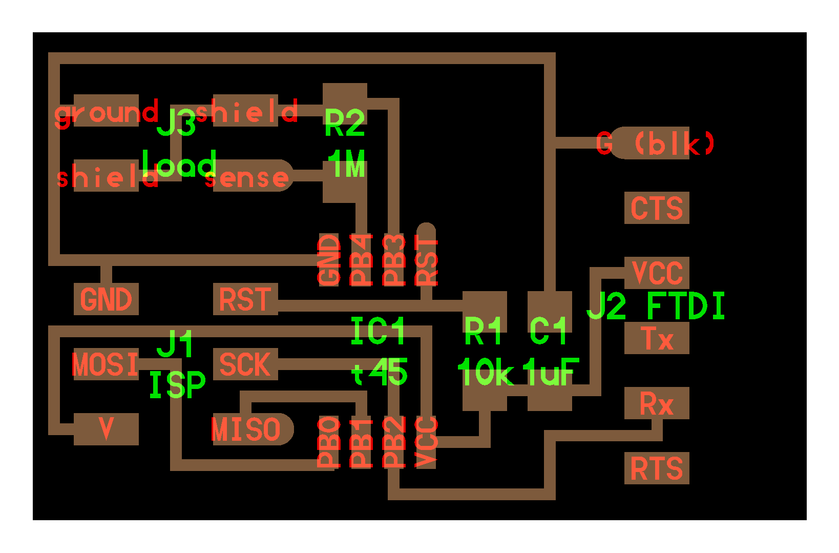
For the input board, I chose the touch sensor board that used the capacitance I want to use in the final project.
In order to be able to perceive when pouring sake. As Mr. Takemura of Guru was working on the assigments of Fab Academy, I referred it.
Quote: Masato Takemura (2014)
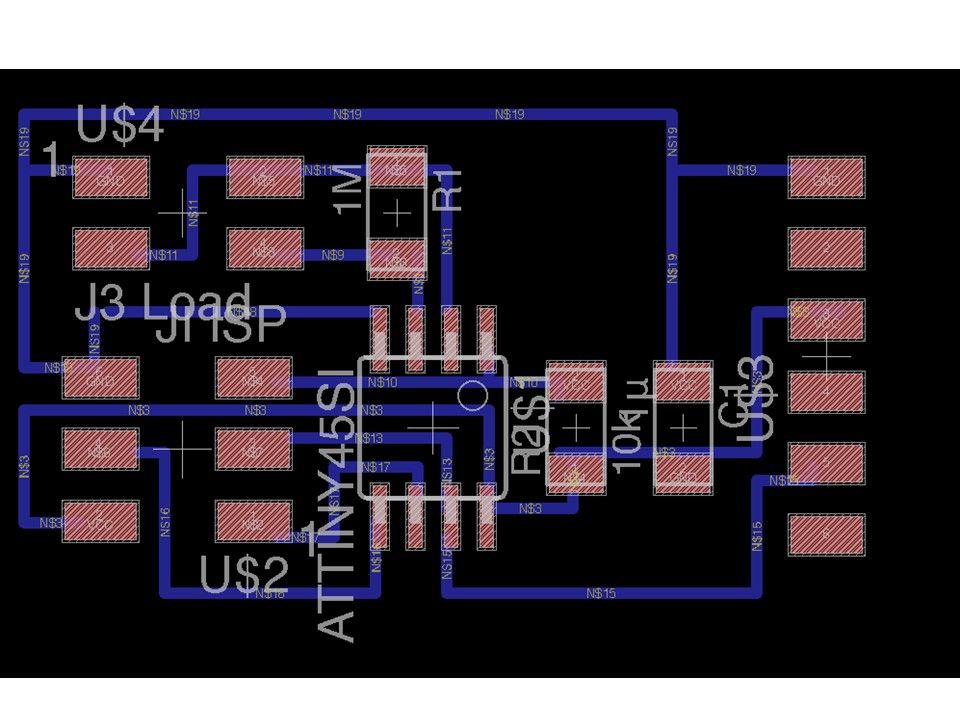
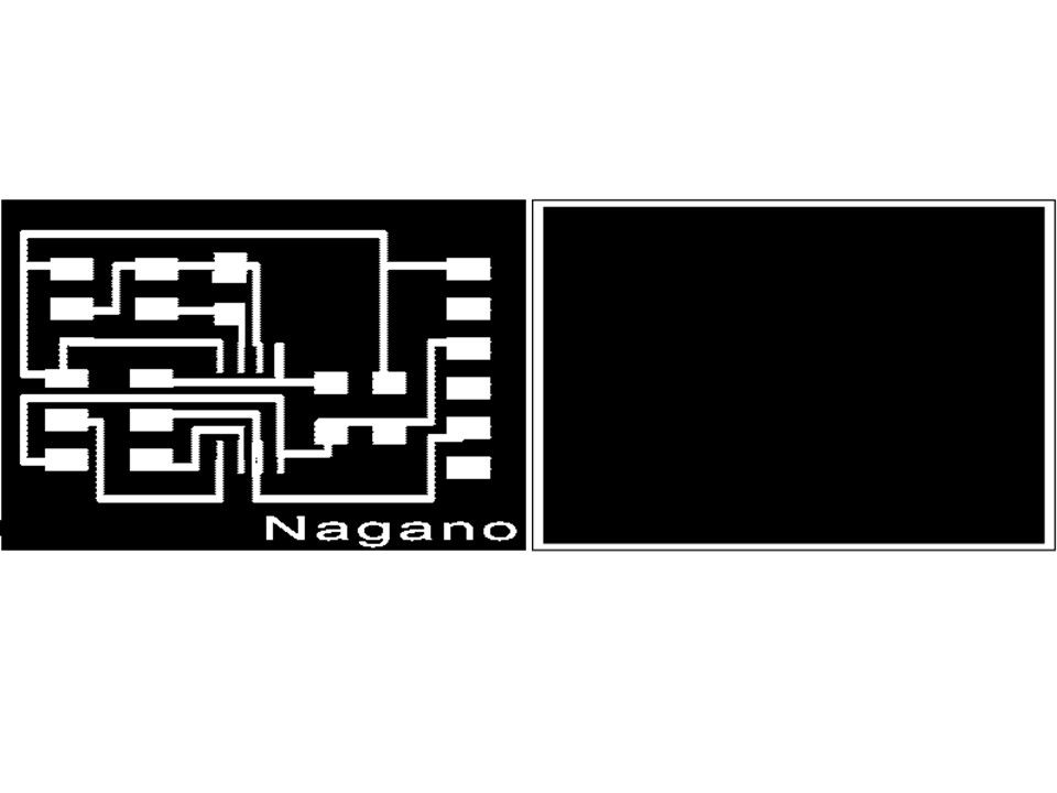
The sample circuit was reproduced with Eagle, and the board pattern was produced.
2. Operation test
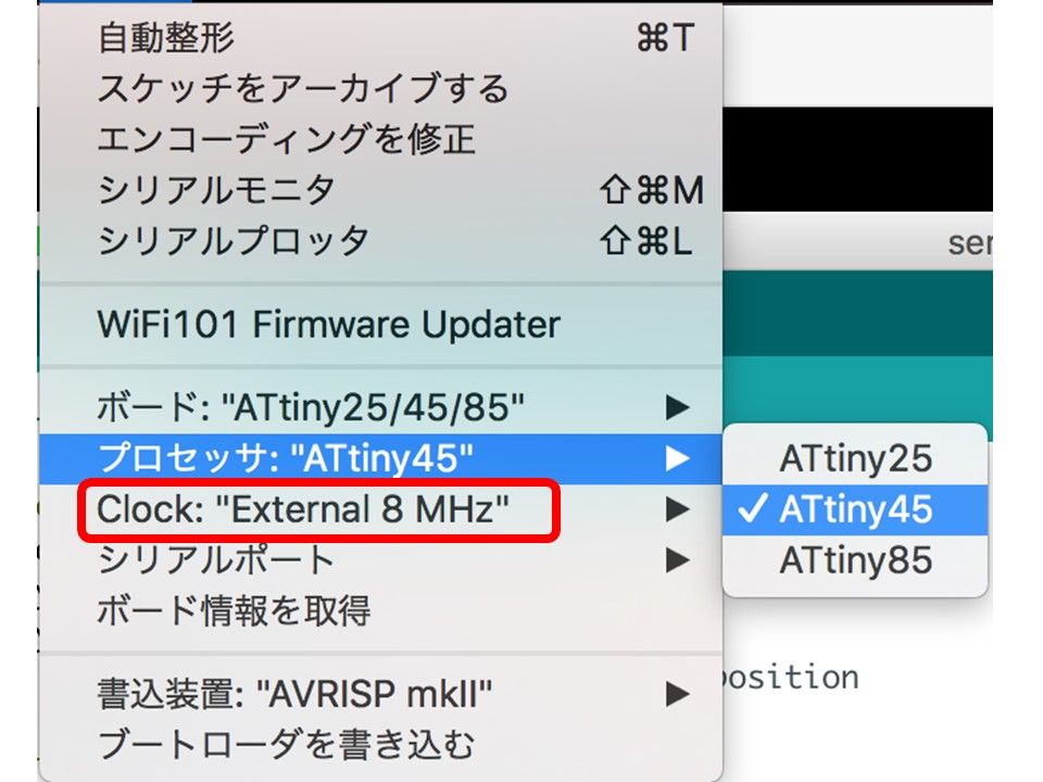
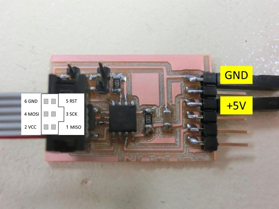
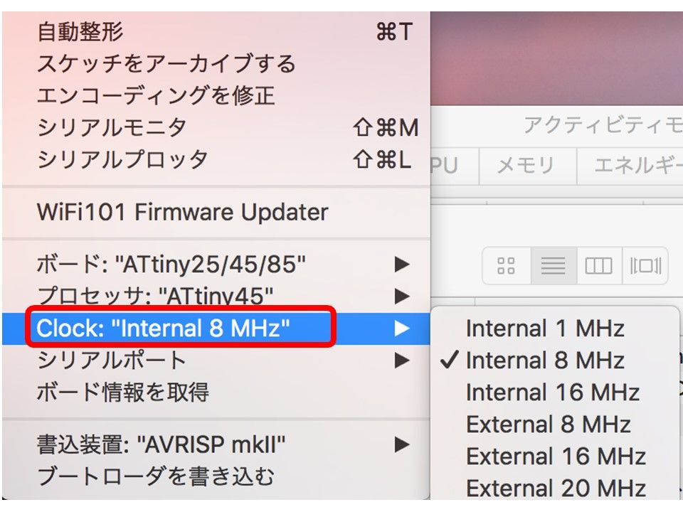
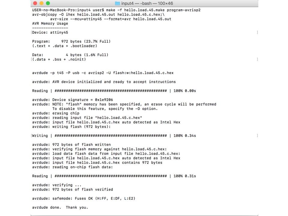
After connecting the AVR writer to the completed board and writing the boot loader, the writing succeeded. However, later Sketch's attempts were made several times but it got an error. As a result of checking, the microcomputer clock had to be set to external 8 MHz although it had to be set to internal 8 MHz.
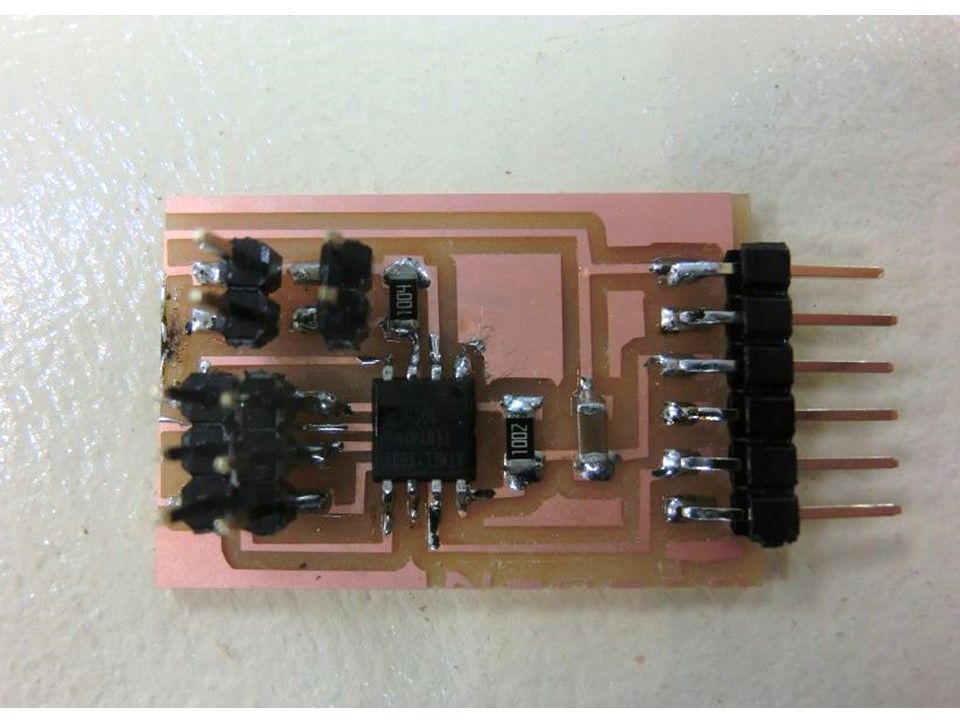
Because it was written in the microcomputer, I had to exchange the microcomputer itself. Since the number of parts is small, I prducted the board again. Components other than the microcomputer were reused from the failed board.
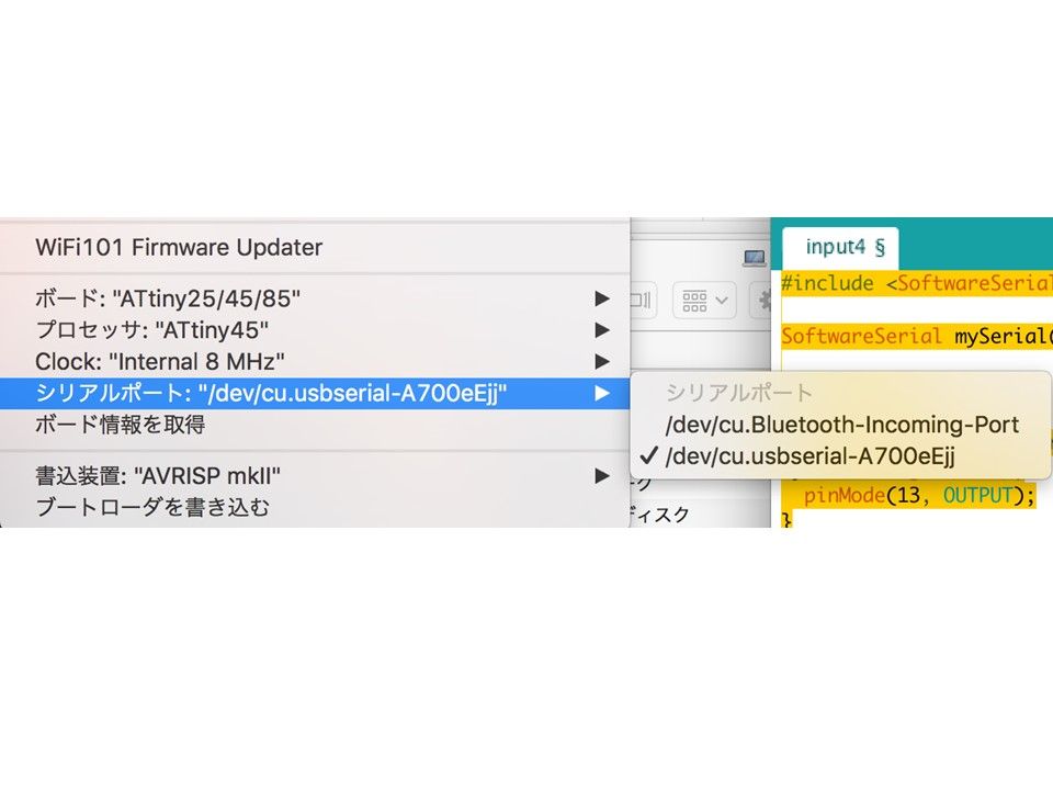
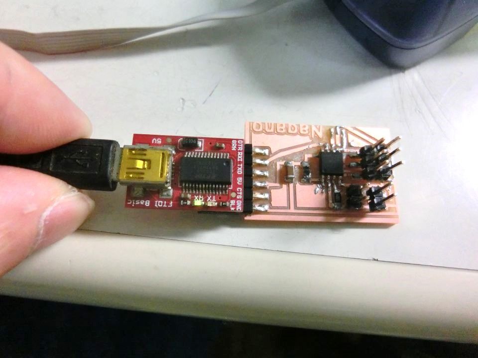
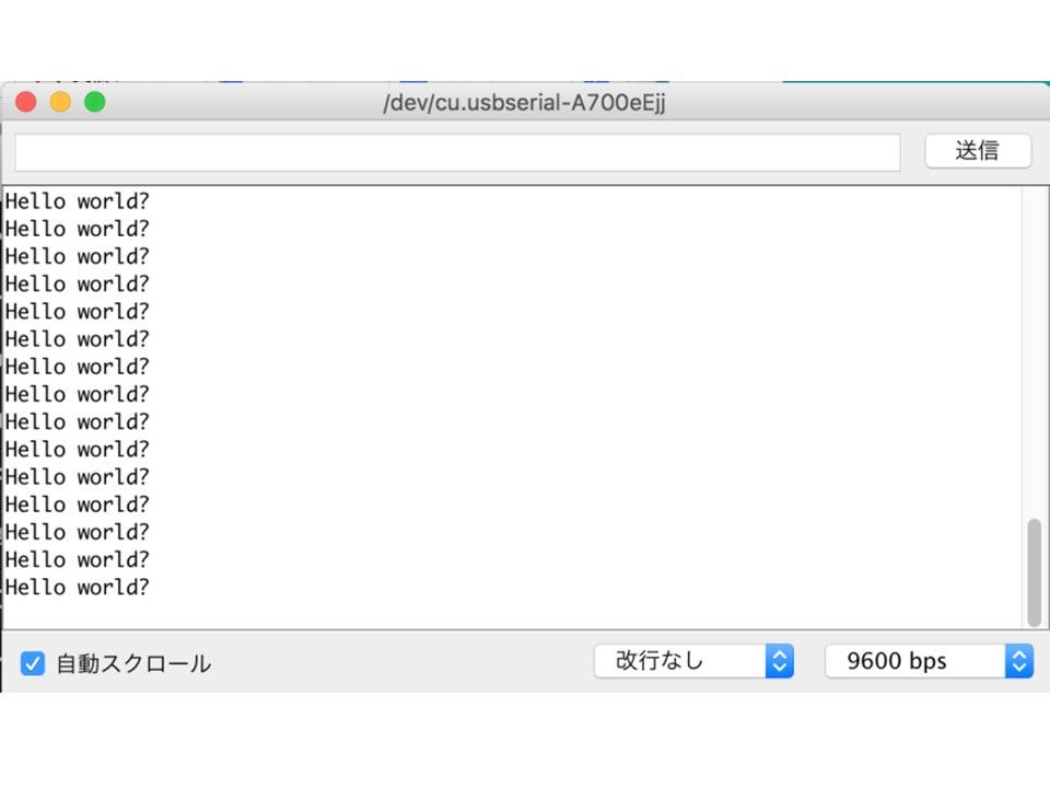
I confirmed that the clock of the microcomputer was set to internal 8 MHz, and I wrote the boot loader. I also succeeded in writing sample sketches. I decided to connect the FDI cable and confirm the reception of data from the microcomputer with the serial monitor.
I confirmed that the serial port was connected.
The state of the serial monitor is as follows.
3. programming
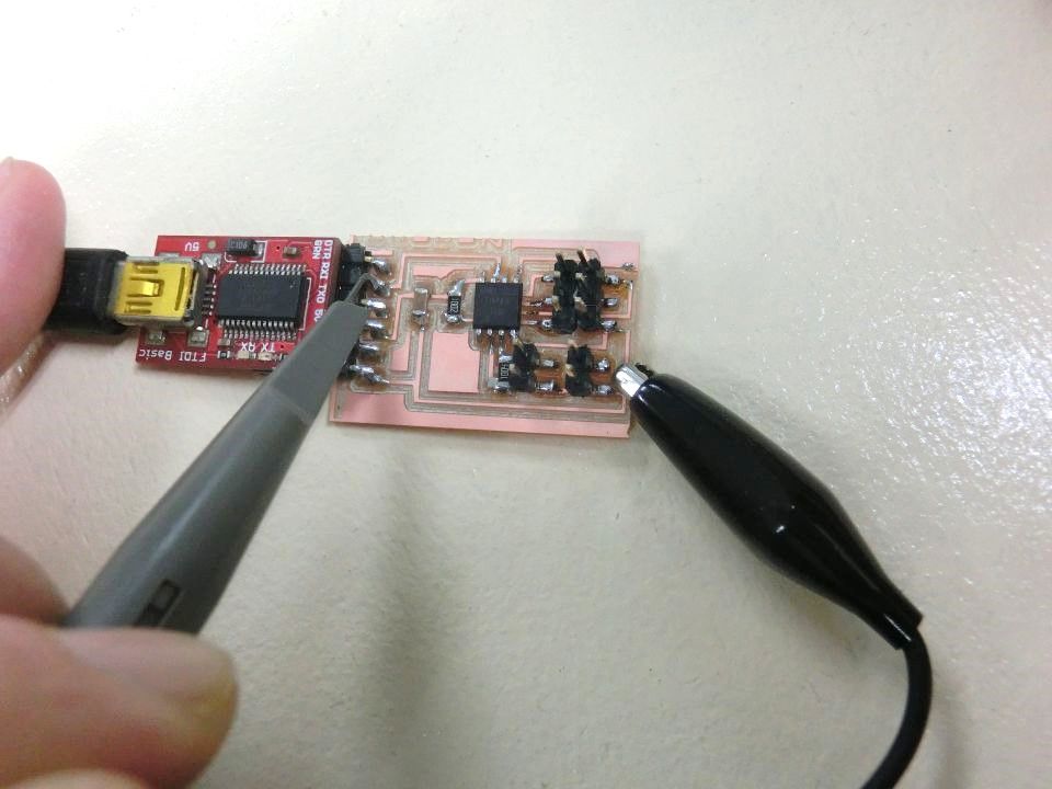
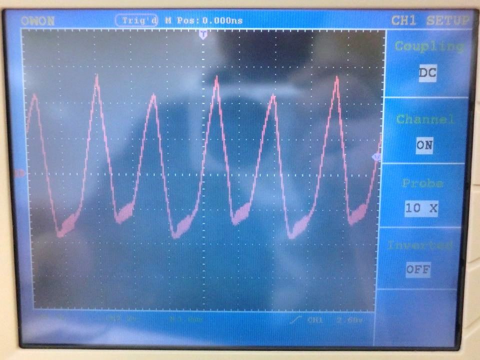
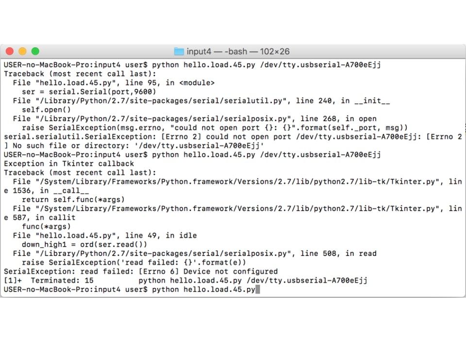
Since I got a board, I wrote the boot loader and succeeded in writing. Next, a program for transmitting character strings was written using software serial communication. However, I confirmed the serial monitor, but I could not confirm it. I changed the pin number to communicate but it did not work. I checked with an oscilloscope and it seemed that there was a signal.
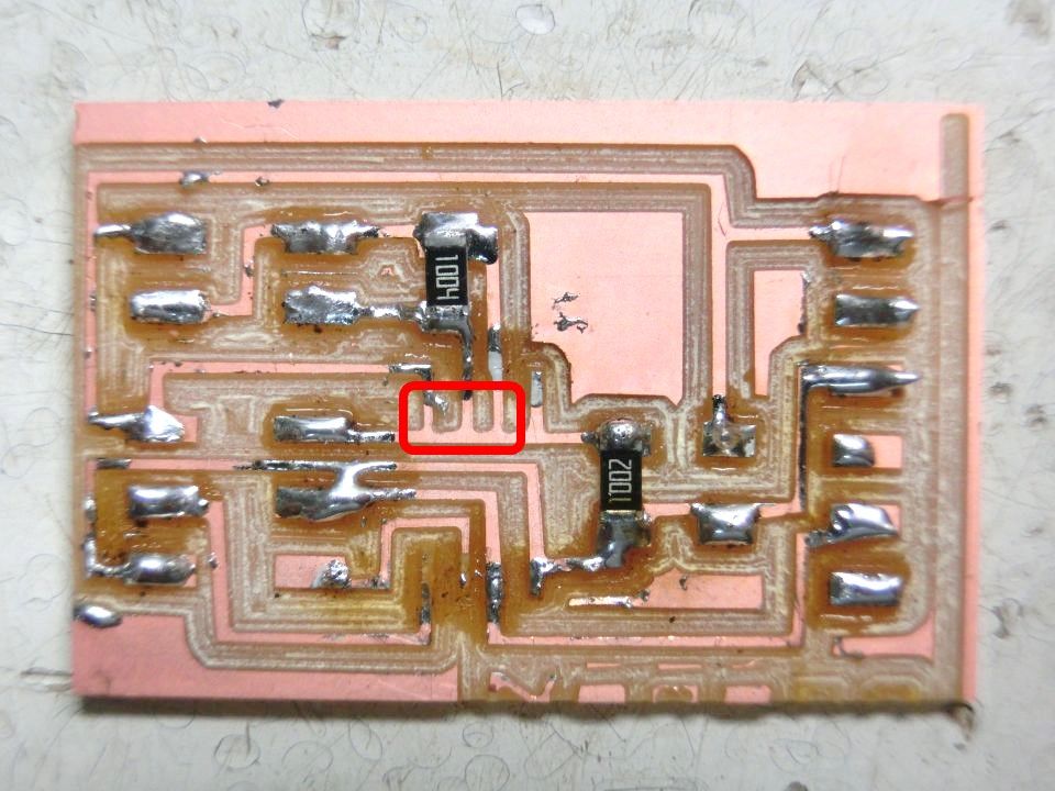
So I discussed with Guru. Guru checked the board, and it turned out that there was a possibility that MOSI terminal and 3 and 4 pins of ATtiny 45 were short-circuited. When I removed the chip, I found a part that was not separated at cutting by the pattern of the board. I overlooked it when checking the board. Since the program was able to write, it was a mistake that did not assume a failure of the circuit. I corrected the pattern and checked the circuit. Since it was all OK, I wrote.
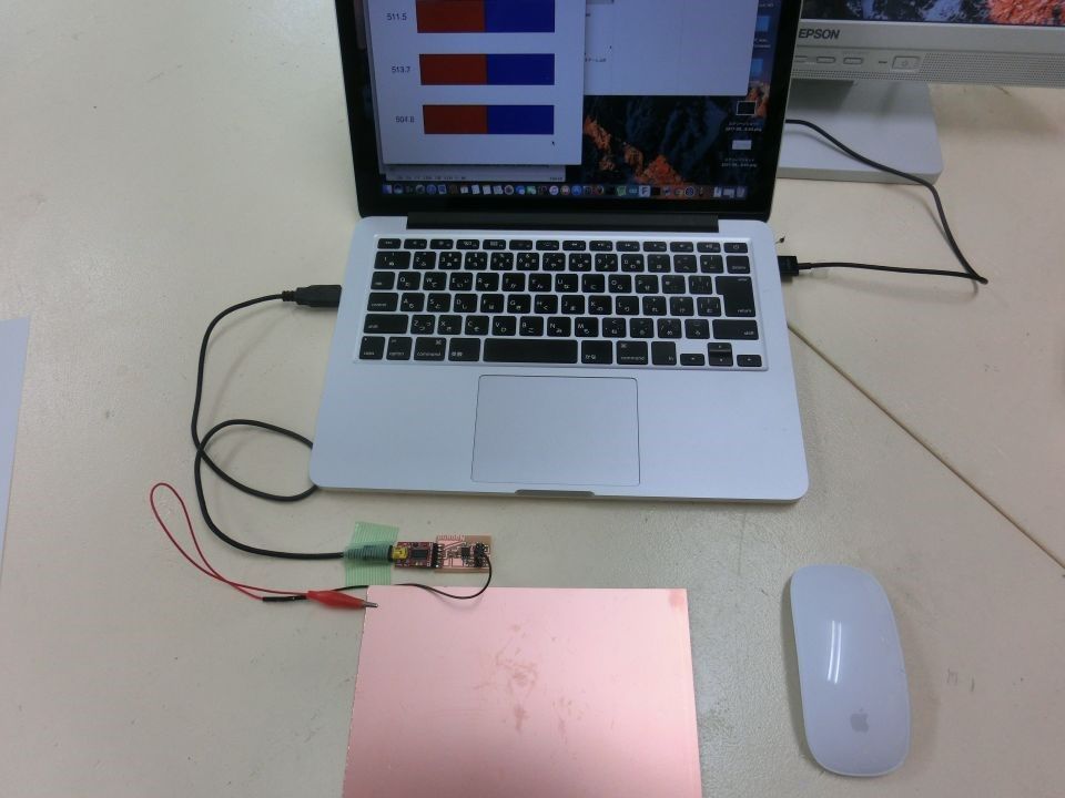
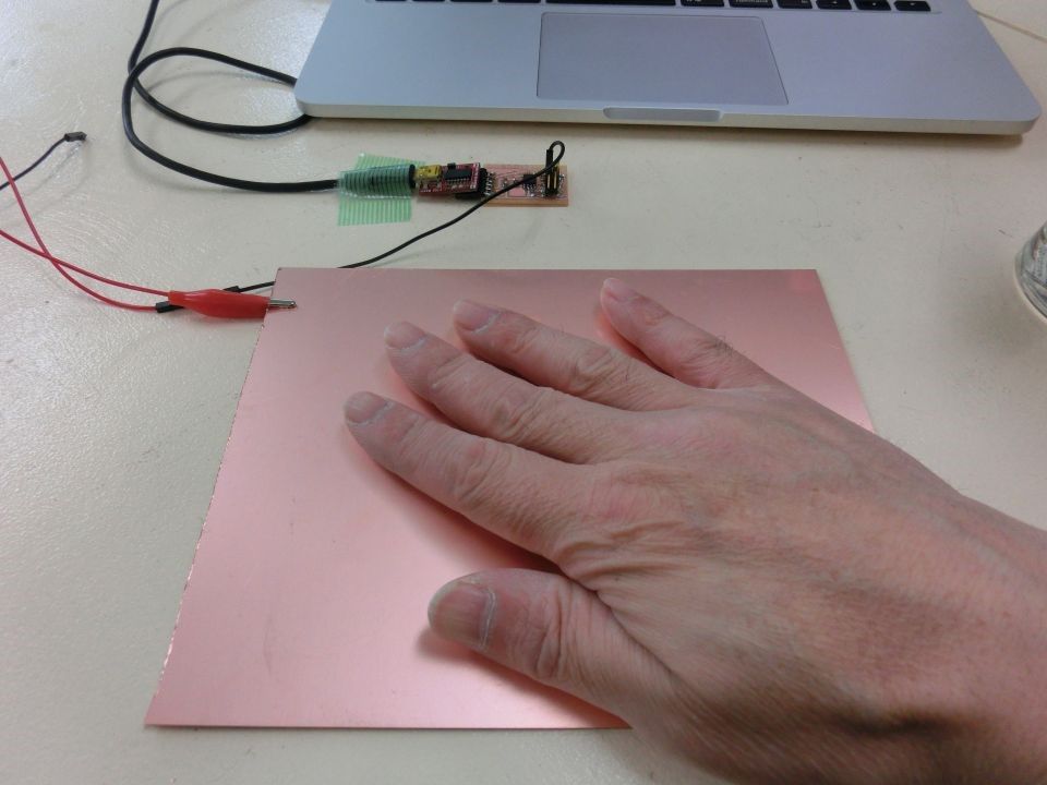
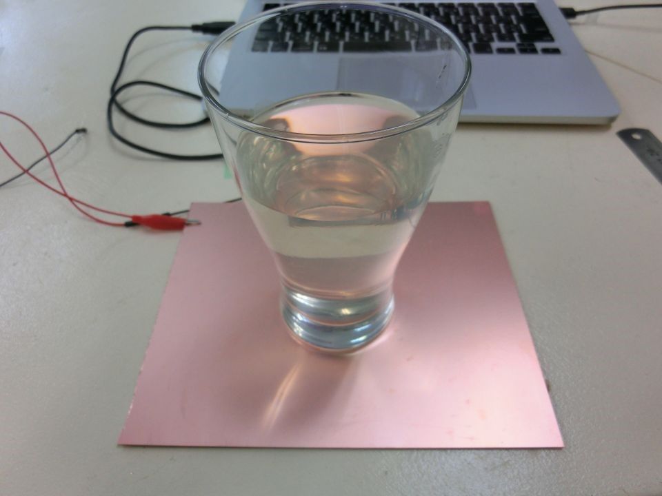
First I wrote it in a sample C language program. Next, I also executed the sample Python program. Indicates a recorded moving image at the time of execution. I can see that I am sensing my hands on it. I tried putting a glass filled with water, but the movement was very slight.
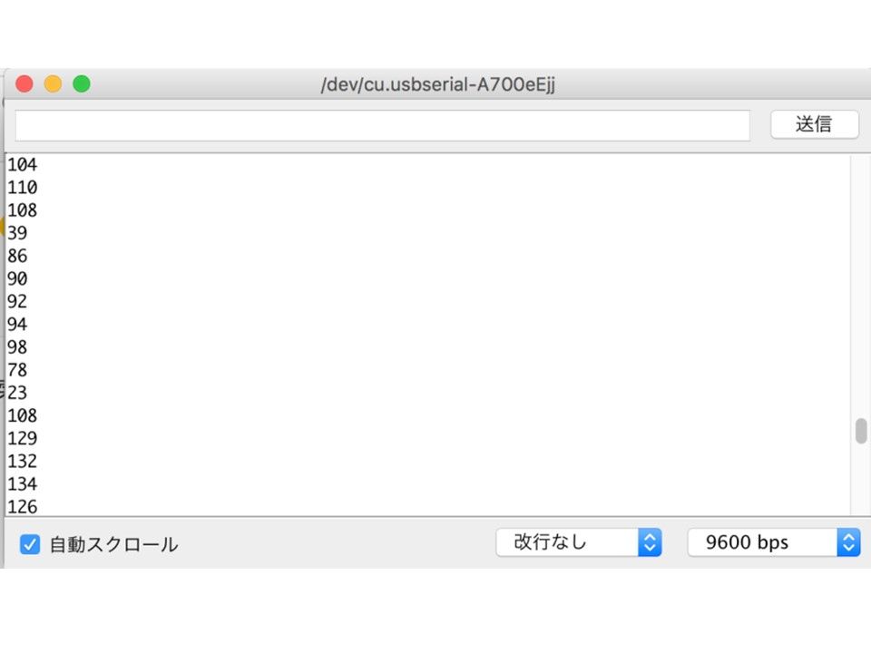
This time, I wrote the program from ArudinoIDE I tried first. First, I was able to check the first character string transmission on the serial monitor. So I wrote a program to check capacitance.
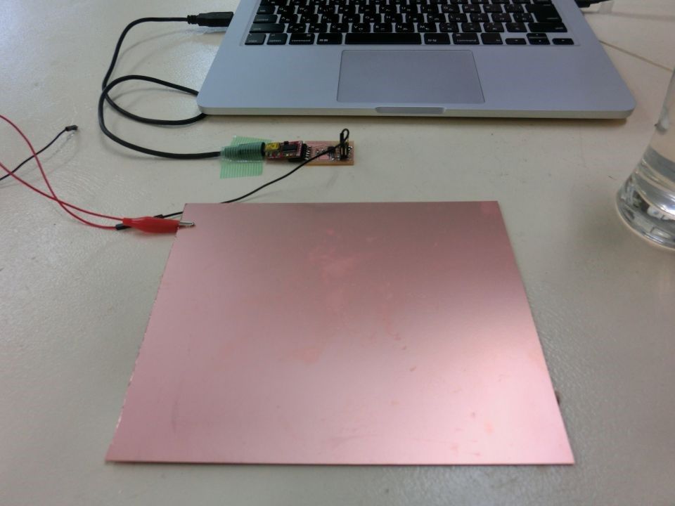
Indicates a recorded moving image at the time of execution. Average value of received data
-Do not put anything on it: 141.6
-Human hand touch: 12.8
-Water filled cup: 89.2
From this result, it was confirmed that alcohol that poured into the glass which was the original purpose could be sensed.


