1. Board design and fabrication
For the assigments of the output device, I chose the servo motor control board. It uses servo motors in his final project.
I referred to the servo sample circuit shown in the lecture.
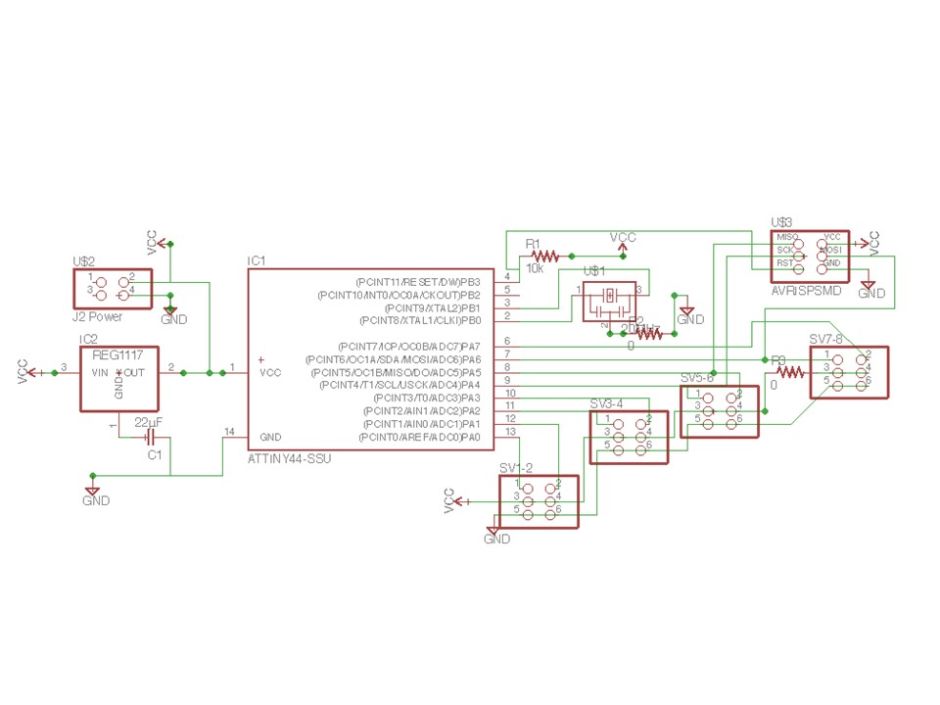
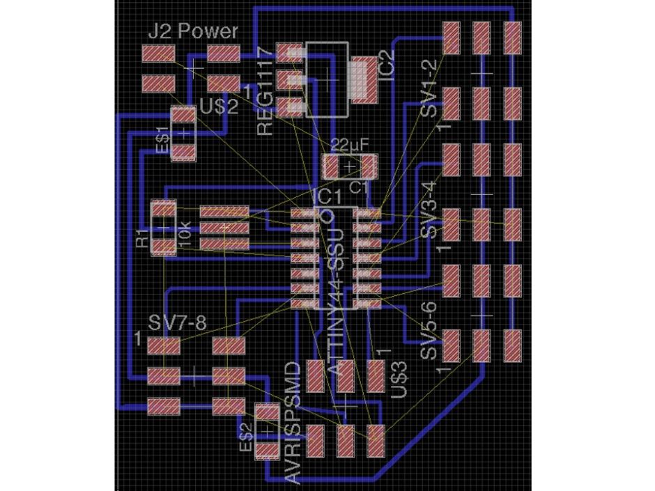
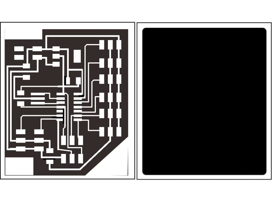
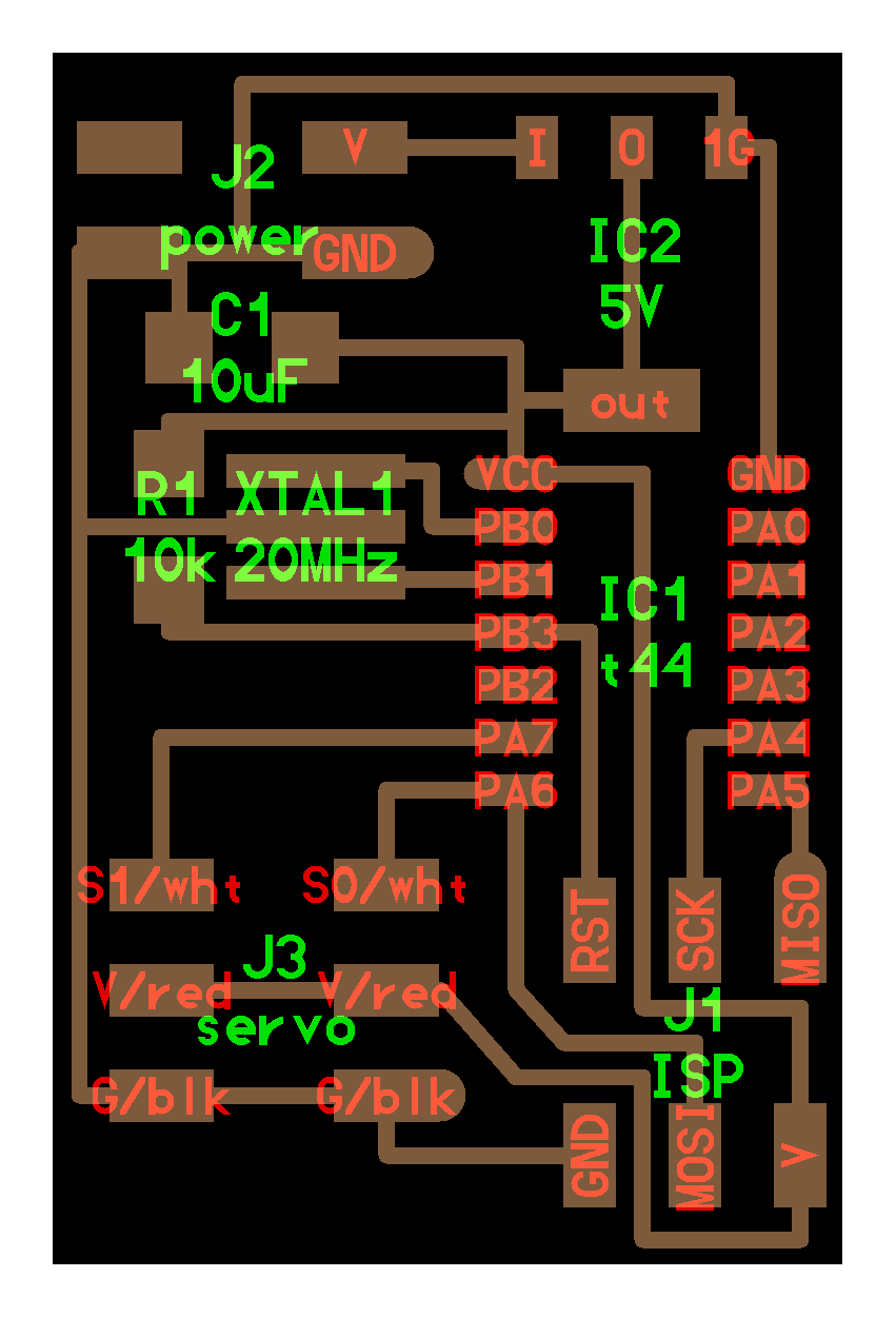
I used Eagle for circuit design. I designed the circuit so that we can control seven servos for the final project. The servo output was pulled out from each pin. Image output of pattern with Eagle.
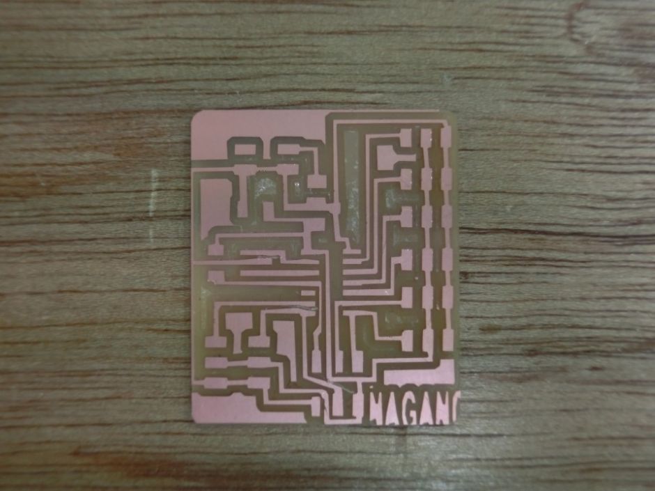
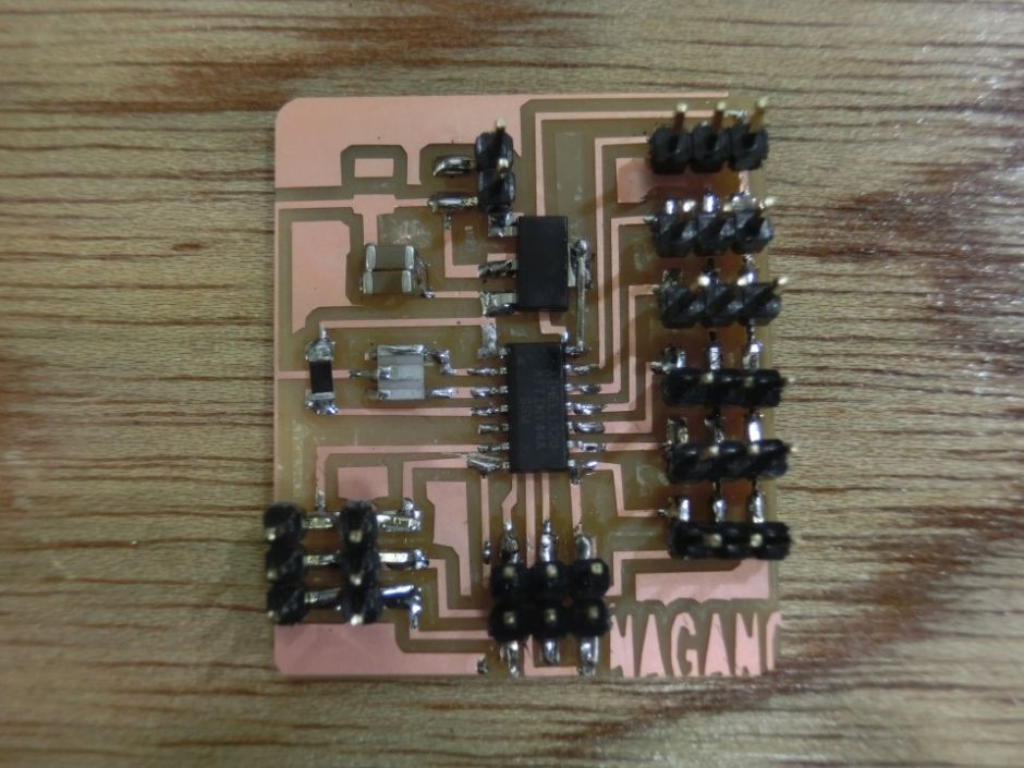
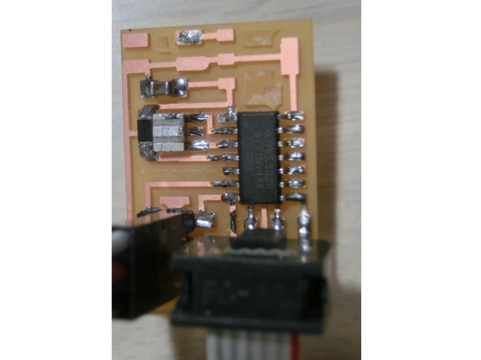
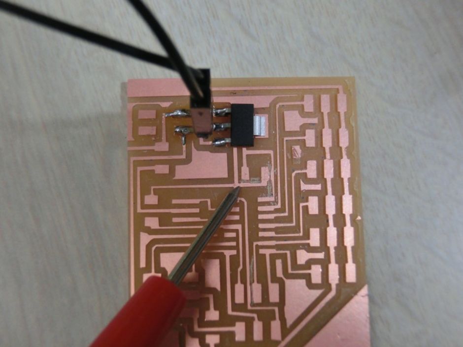
I made boards with Roland's SRM-20. The photograph is a circuit which has been assembled.
2. Operation test
A circuit check was made on the completed board and the power supply was connected.
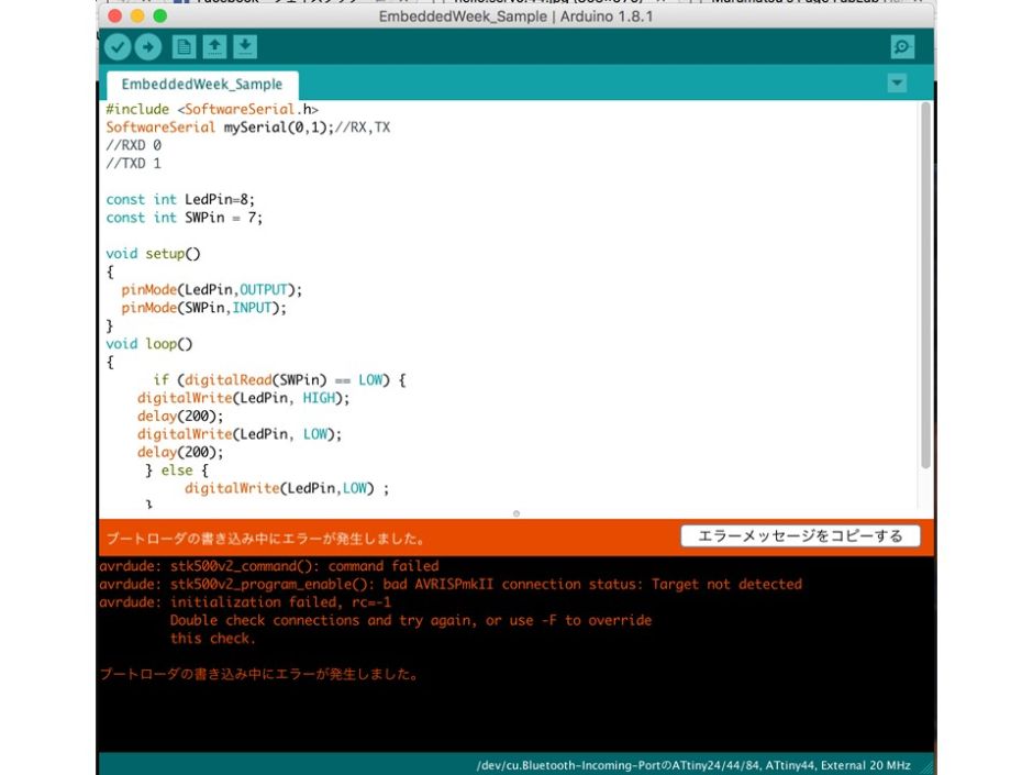
ATtiny 44 was used for the microcomputer. First I wrote the bootloader using ArudinoIDE, but it got an error.
I confirmed it again but no error was found. At that time I noticed that the 5V power regulator had abnormal heat. But I could not find any mistakes in the circuit. Therefore, I tried to make it according to the servo sample circuit shown in the lecture. I wrote a bootloader using ArudinoIDE, but an error similarly occurred. Also, the regulator was getting hot as well.
I started investigating thinking that it was a fundamental problem. As I looked it up, I found that last year's students had trouble with the same power supply. In his case, it was resolved by taking another power supply. -http://archive.fabacademy.org/2016/charlottelatin/students/87/exercise13.html
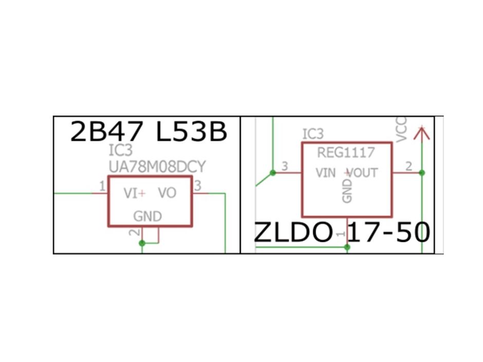
At that time, Guru who consulted this trouble discovered information that the terminal of the regulator is different. It is the following page.
According to this information, it was said that the pin assignment was changed because the model number of the regulator changed as shown in the figure. -http://archive.fabacademy.org/2016/fablabtecsup/students/363/content/assignments/assignment-13.html
Quoted: FABIO IBARRA
So I tried doing the same, I made the board again. When using the regulator, if you directly connected the power supply, the boot loader was successfully written. Next, I wrote the basic program to move the servo, and it was confirmed that the servo motor moves.
3. Improvement of substrate
Since the regulator problem was solved, I redesigned the board again. The connection of the terminal of the regulator was changed for a new part.
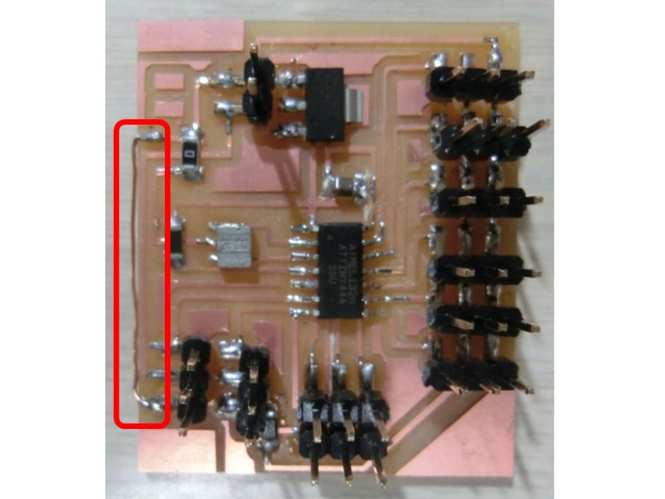
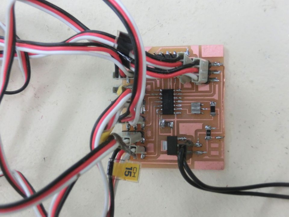
After cutting, only the regulator was soldered, and it was confirmed that the voltage was output at 5 V and that there was no abnormal heat generation.
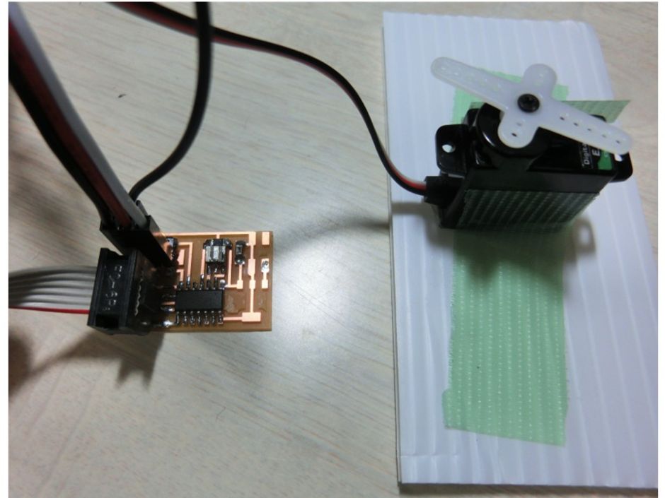
Because the board pattern was partially cut, it was connected with a jumper wire. The completed substrate is as shown in the pictuer.
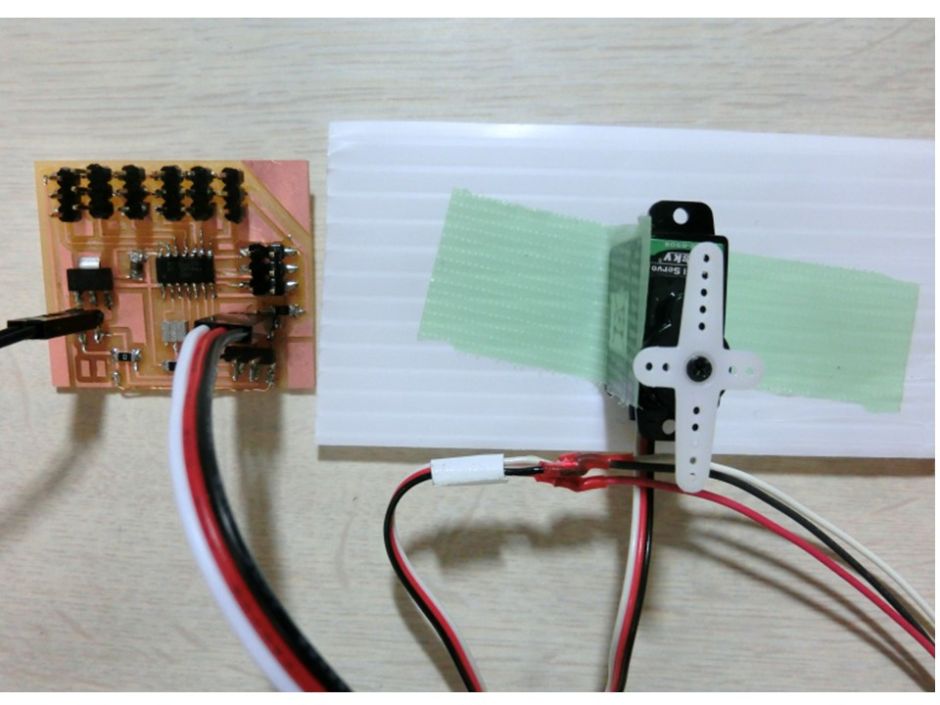
4. programming
The servo test program is as follows. I could confirm that the servo worked like a video. Since a regulator can be used, it can be used by simply preparing a power supply for servo.
#include
int led = 8;
Servo myservo1;
Servo myservo2; //create servo object
int pos = 0; //variable to store the servo position

void setup()
{
  // initialize the digital pin as an output
  pinMode(led,OUTPUT);
  myservo1.attach(7); // servo1 on pin 7
//  myservo2.attach(6); // servo2 on pin 6
}

void loop()
{
  //
  digitalWrite(led,HIGH);
  delay(100);
  digitalWrite(led,LOW);
  delay(100);
  for (pos = 0; pos <=180; pos +=1)
  {
    myservo1.write(pos);
//    myservo2.write(pos);
    delay(1000);
  }
  for (pos = 180; pos>=0; pos -=1)
  {
    myservo1.write(pos);
//    myservo2.write(pos);
    delay(1000);
  }
It worked like the video below.
The servo motor used in the first experiment was a compact SG90. Because the servo movement was not good, I replaced it with another servomotor (MG995, TowerPro). Specification of servo motor.
- Control angle = 180
- PWM cycle = 20 ms
- Control pulse = 0.5 ms - 2.4 ms
- Torque 10 kgf / cm (6 V)
When I changed the servo, it started to work lightly.
The servo seemed to be moving, but the servo did not move except for pin 6.
As a result of discussion with Guru, we reached the conclusion that the servo is not moving but it is returning with a reset signal at the time of startup. After investigating, ATtiny44 did not work with Arudino's standard servo library. According to this site below, the reason for not working is that ATtiny only has an 8-bit timer, whereas the servo library relied on a 16-bit timer. Quote: Cunning Turtle,ATtiny 45/85 Servo Library http://www.cunningturtle.com/attiny4585-servo-library/
I copied the downloaded library into the library folder of arudino. When writing the sketch below, it was confirmed that two servos were moving.
include

  SoftwareServo myservo1;
  SoftwareServo myservo2;
    int pos = 0;

void setup()
{
  myservo1.attach(6);    // attaches the servo on PB1 to the servo object
  myservo2.attach(7);
}

void loop()
{
    myservo1.write(0);
    delay(100);
    SoftwareServo::refresh();
    myservo1.write(180);
    delay(100);
    SoftwareServo::refresh();
    myservo2.write(0);
    delay(100);
    SoftwareServo::refresh();
    myservo2.write(180);
    delay(100);
    SoftwareServo::refresh();
}
I changed the servo used to the servo that I plan to use in the final project. The servo specifications are as follows. KRS-788 (Kondo Kagaku CO.Ltd)
-Maximum Torque: 10.0 kgf/cm
-Power supply voltage: (9 V to 12 V)
-Maximum large operating angle: 180
-Communication standard: ICS (PWM only)
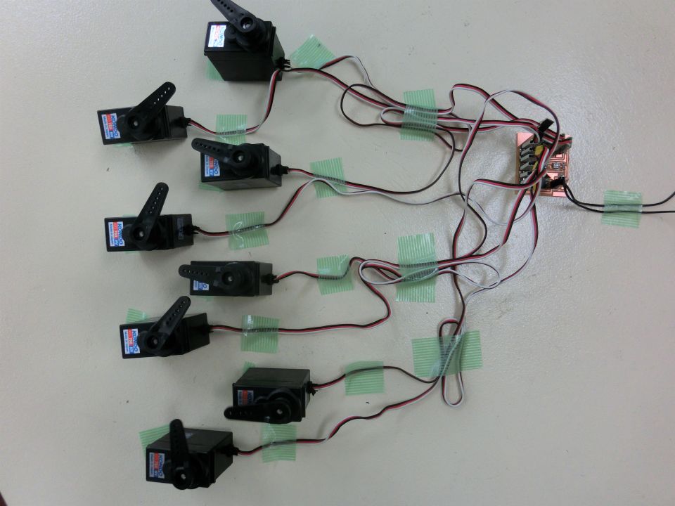
I connected eight servos which are the upper limit of ATtiny44. In the experiment, the operation was unstable due to insufficient supply current of the power supply, so it was replaced with a larger power supply.
As a result of the experiment, we succeeded in controlling 8 servos like video.
I could not solve it for the last 3 weeks, but I could solve the problem with Guru's cooperation. I thank Mr. Takemura of Guru.


