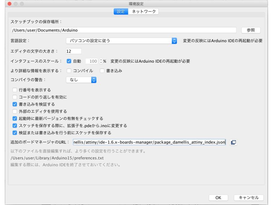
1. Setup of ArudinoIDE
After installing ArudinoIDE, I set up to use Attiny. Worked on the basis of the information of the website that Guru taught.
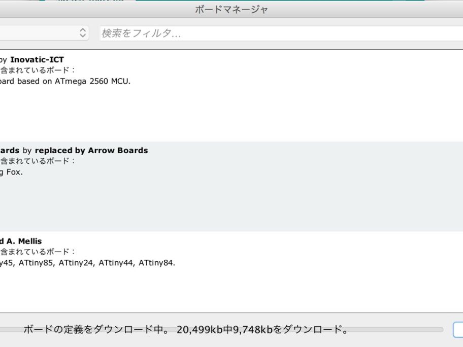
Copied the URL of the specified information and set it in the board manager. Added Attiny to the board manager. This made it possible to use the board.
2. Bootloader write
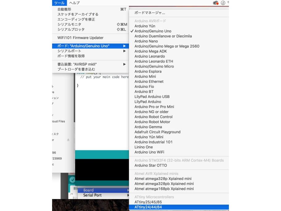
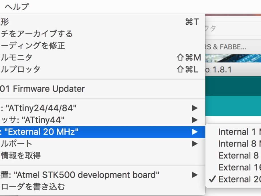
According to the data sheet, ATtiny 44 clock frequency selected 20 MHz.
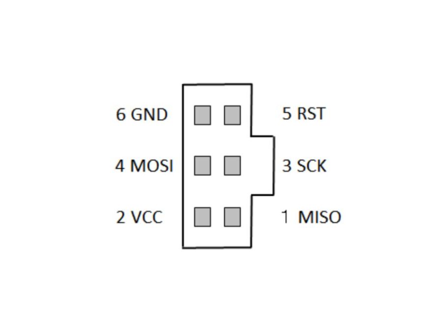
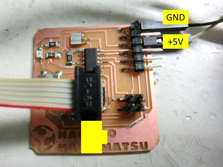
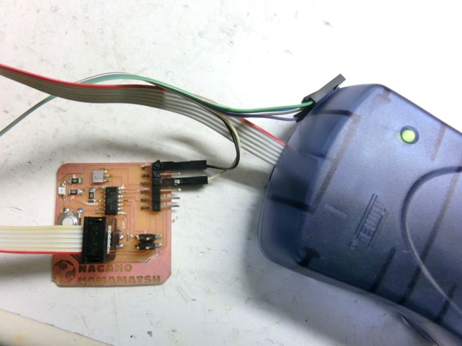
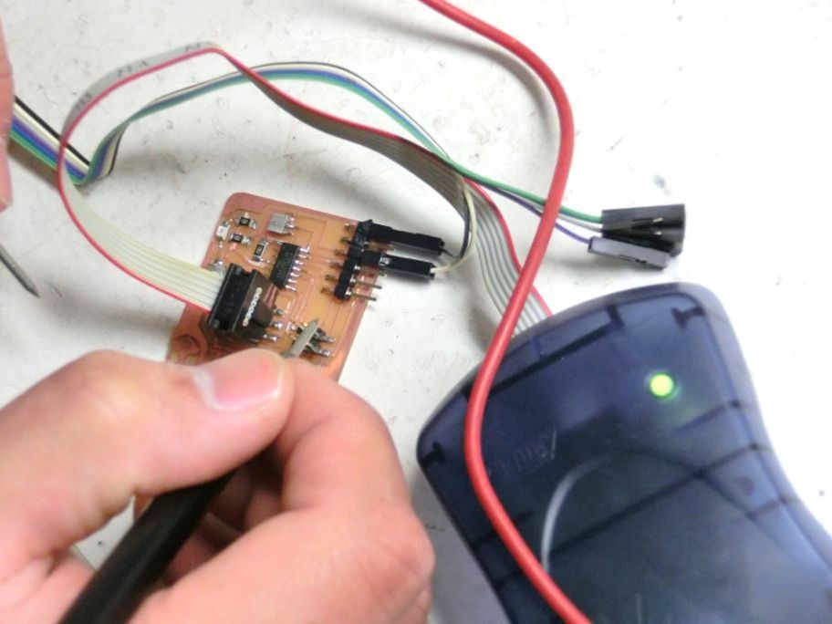
I used AVRISPII to write the program. Because Fabisp was not working well at this stage. I connected the board with the AVRISPII. I checked the direction of the connector and connected.
Refer to the following page for the orientation of the connector.
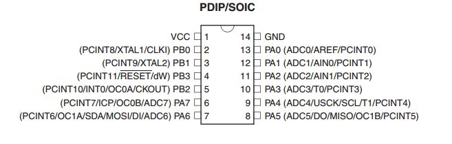
Check the datasheet
I checked the ATtiny 44 data sheet. I checked the placement of the pins and checked for mistakes in the connection.
-Datasheet Atmel Corporation
Question by reading the data sheet
I understood the pin arrangement and physical characteristics. However, although there is explanation about Register, I can not fully understand this usage.
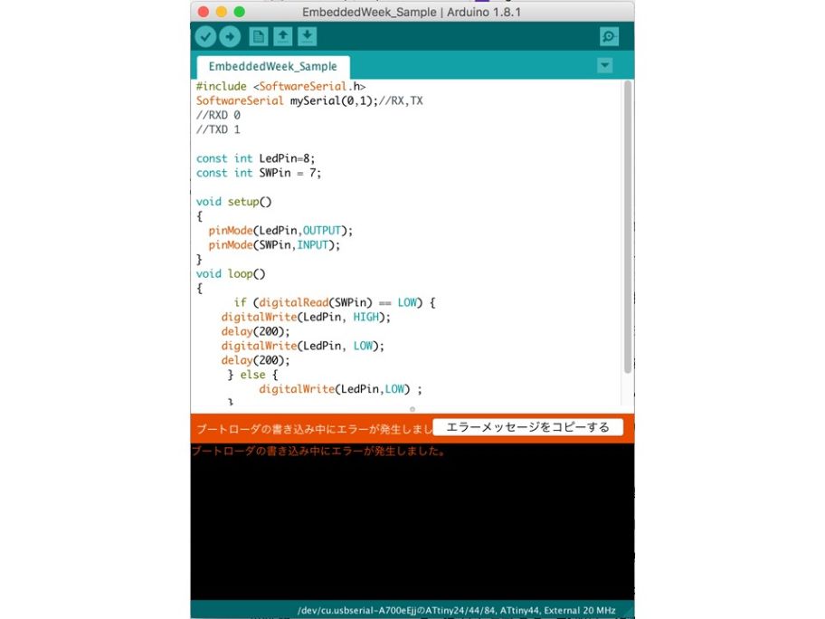
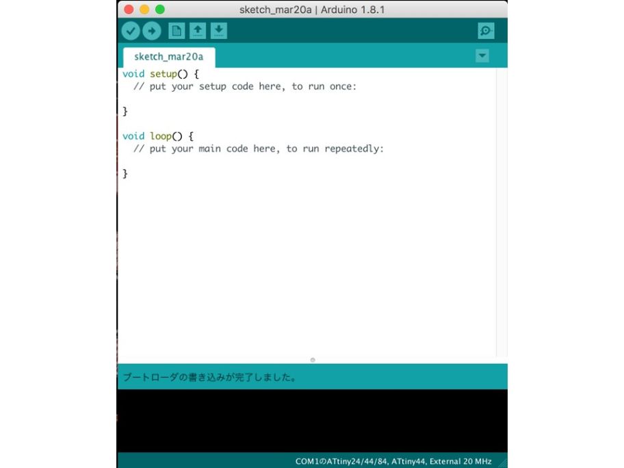
Power source used 5V. I was ready so I wrote the bootloader.
I programmed using arduino IDE and wrote it.
However, as shown in the photo, an error appeared and it did not move.
3. Check the board
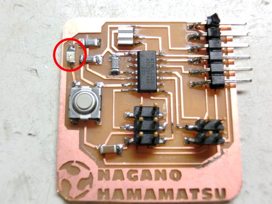
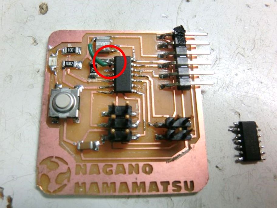
Guru supported me and checked the board using a circuit meter.
Firstly, it was discovered that the circuit pattern was connected. I cut this part with a cutter. Then it turned out that the LEDs were attached in the opposite direction.
I replaced the LED, but the board did not work. As a result of discussion with Guru, it was speculated that the microcomputer itself was broken by reversing the voltage.
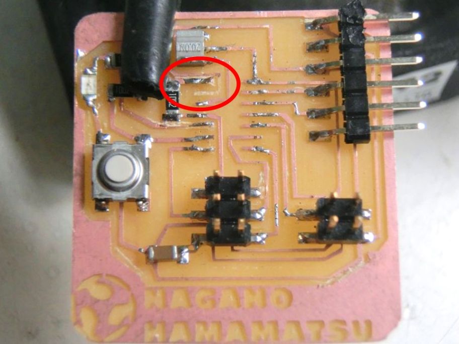
I removed the microcomputer using a soldering iron. I was watching carefully at this time, but the board pattern was broken. I fixed the connection with a jumper wire.
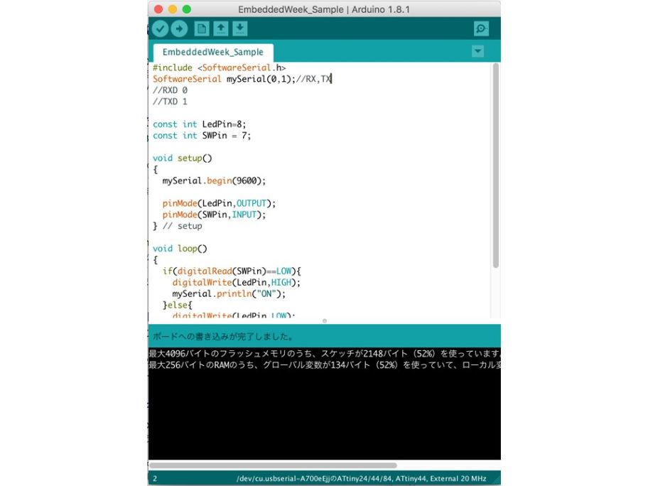
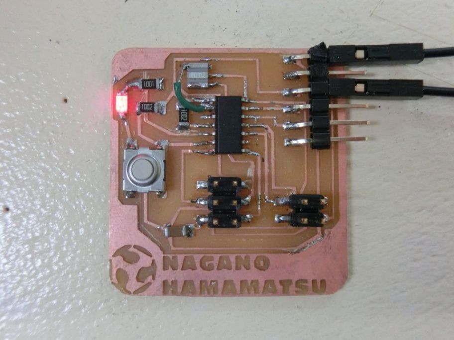
After writing the boot loader again, the writing was successful.
4. Write a sketch
Next I wrote a sketch. At first I wrote sketches to blink the LEDs.