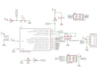
1. Circuit design
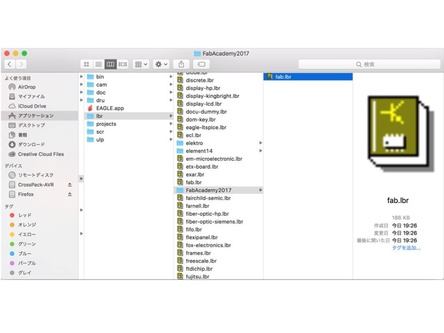
I used Eagle which is the circuit design software. I downloaded the Fab Library from the site(
fab.lib) and installed it to Eagle.

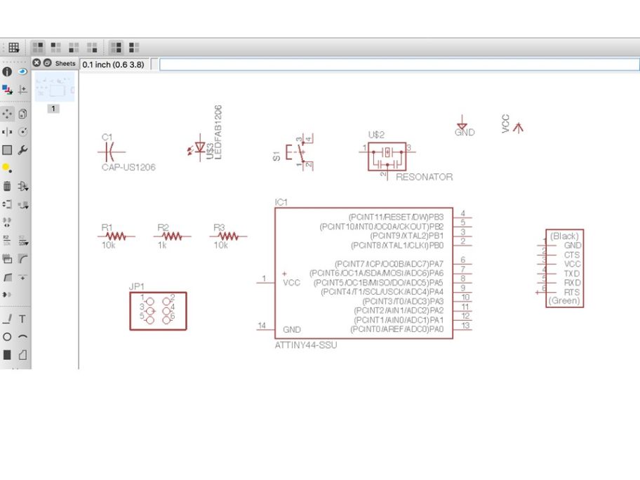
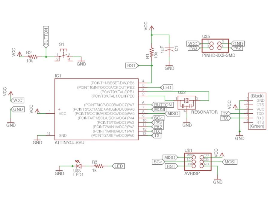
I decided to add LEDs and buttons. Parts were added from the library and arranged.
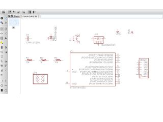
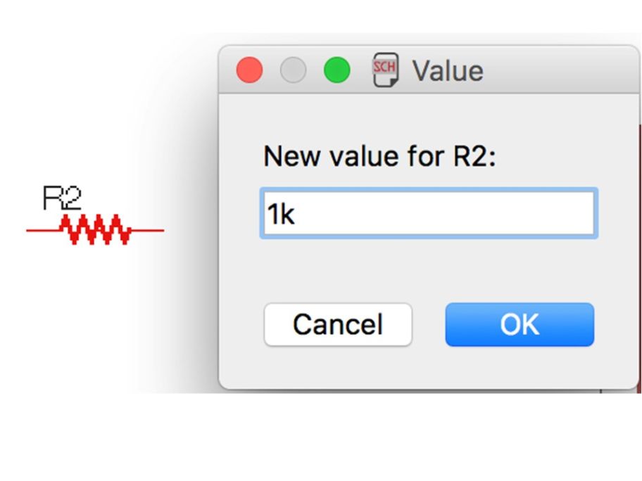
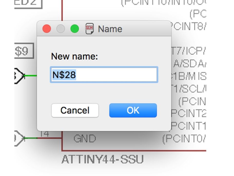
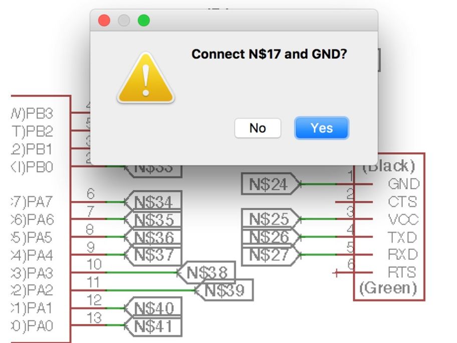
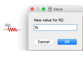
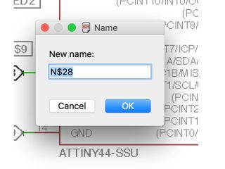
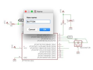
I entered the property of the part such as the resistance value. I labeled the label of the group of parts. When I enter the same label name, confirmation of connection is displayed.
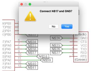
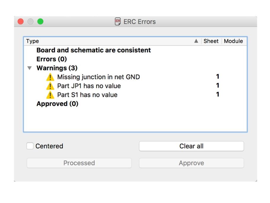
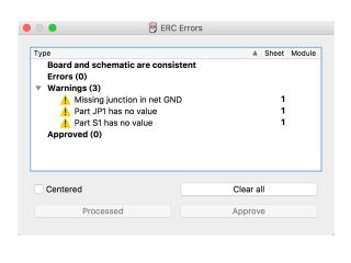
When the connection of the parts was completed, the circuit was checked. There was no error. Some warning were also displayed but judged that there was no problem. This is a completed circuit.
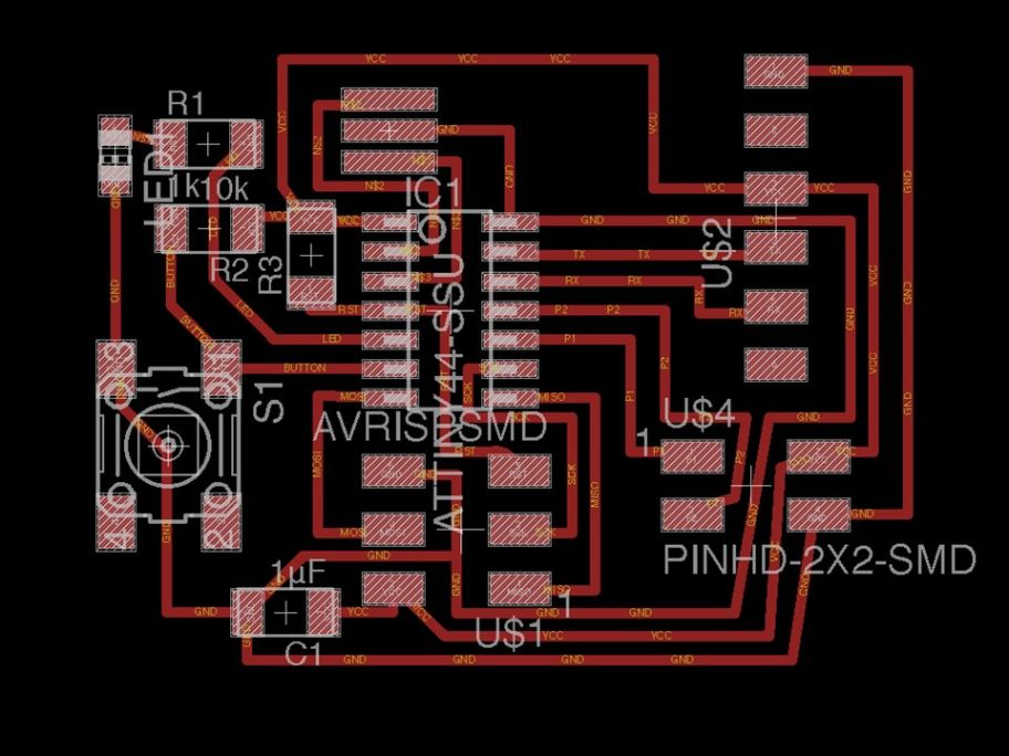
 2. Pattern design
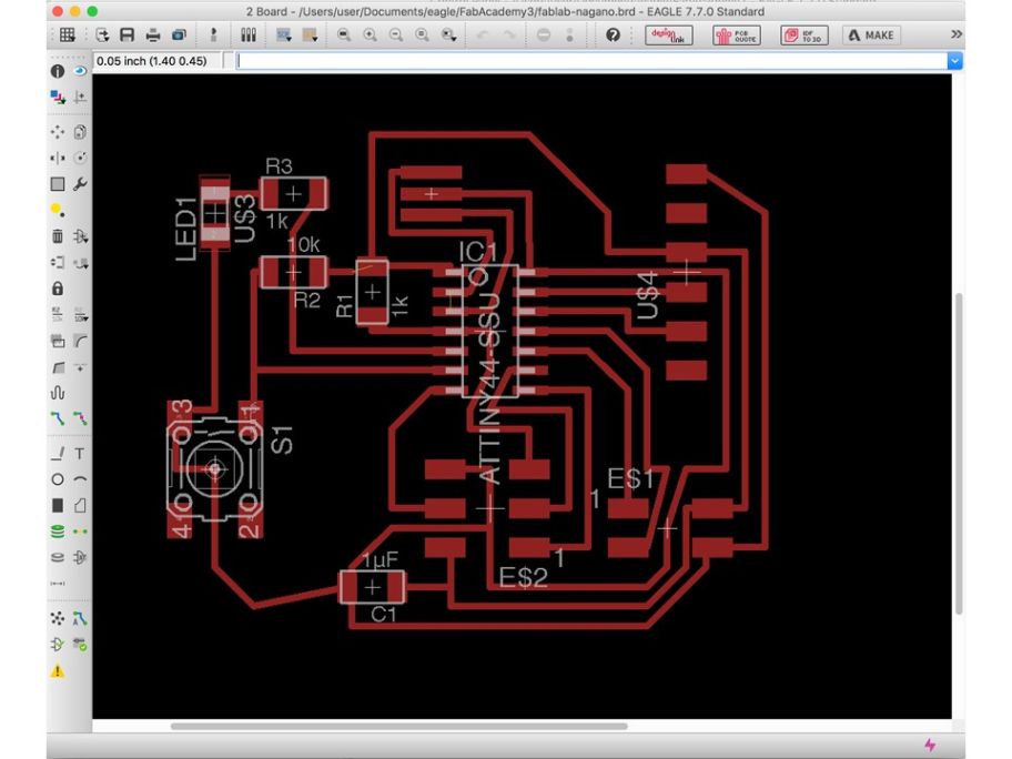
Next, I designed the pattern of the bord. I switched to the pattern design and started designing the pattern. I arranged it while thinking that the patterns did not cross. It is a completed pattern diagram.
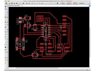
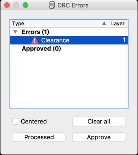
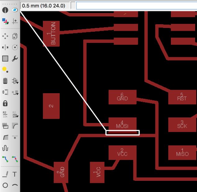
I confirmed EAgle's design rule check (DRC). In the initial setting, since 1 mm = 0.0254 mil, it is necessary to use a 0.2 mm end mill for this processing.
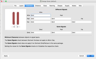
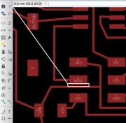
As a result of checking, narrow spots were discovered. Since the pattern was close, I lowered the position of the wiring slightly to cope with it. The error has been resolved.

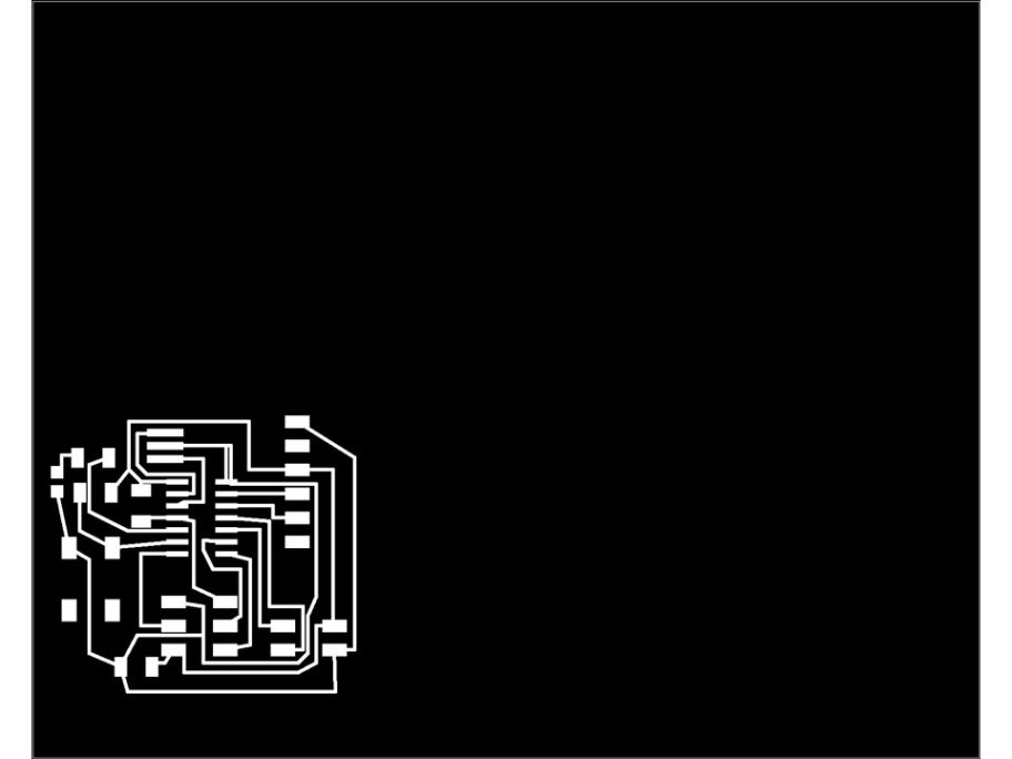
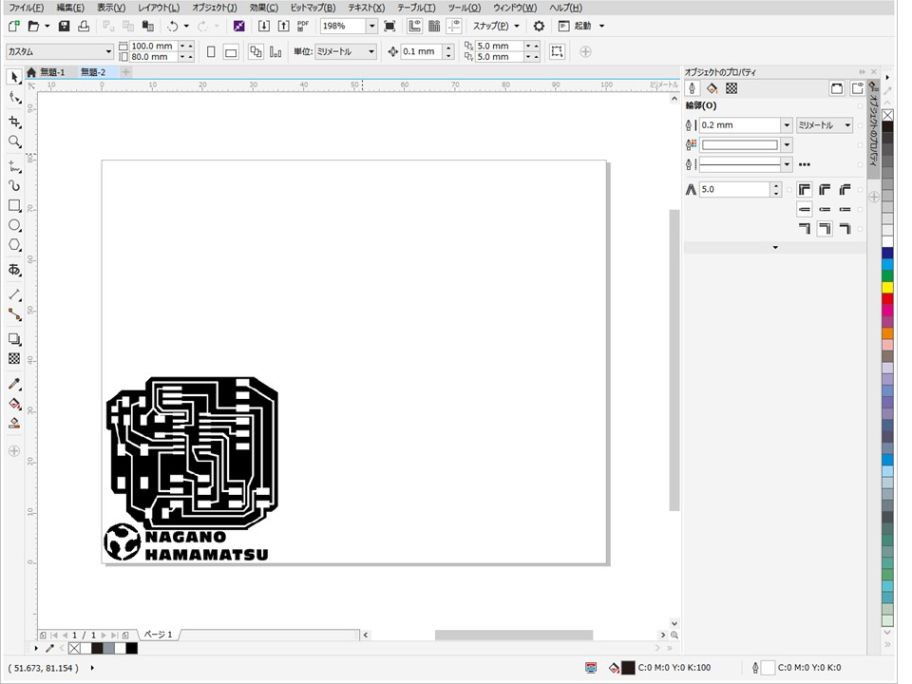
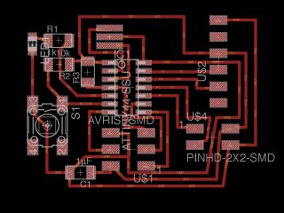
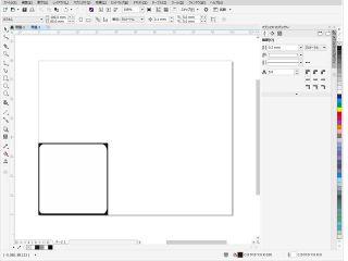
I exported it so that it can be cut image. At that time, I put a check in black and white and output it. CorelDraw X8 was used to correct the substrate image. I modified the part where it was doubled or the pattern was narrow.
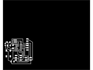
I added texts and images. A cut image of the bord was also created.

It is a processed image of pattern and bord.

 3. Cutting
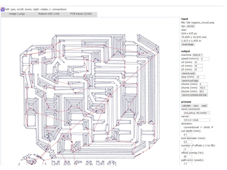
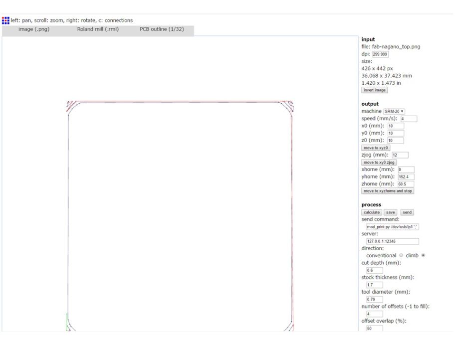
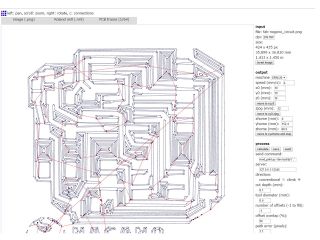
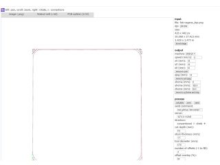
Fiest, Cutting data was generated. I accessed
fabmodules.org and loaded the saved images.
For the pattern data, 1/64 end mill was selected and the repeat count was selected as -1. For the shape data, 1/32 end mill was selected, and the number of iterations was selected as 4. Calculate cutting data and save it after checking.
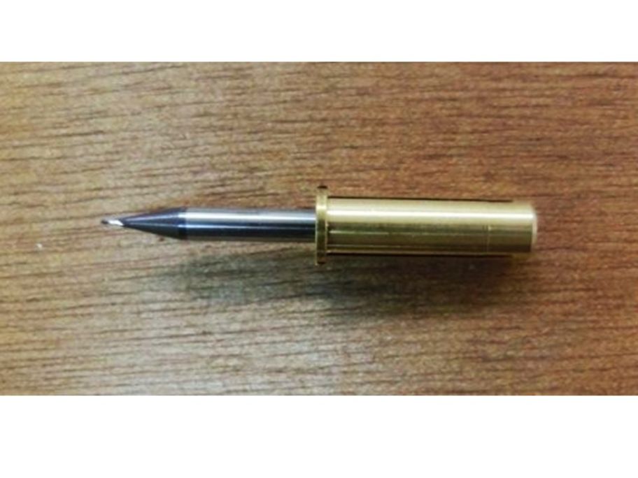
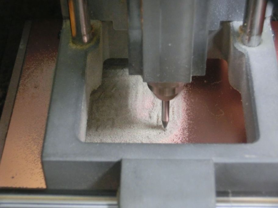
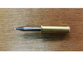
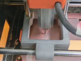
SRM-20 from Roland Co. was used for cutting. 1/64 and 1/32 end mills were used. Because the system of the end mill is thin, I used a collet so that it can be attached to the chuck.
Cutting was started. It took 15 minutes 20 seconds to cut the pattern.
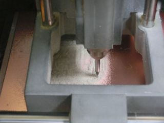
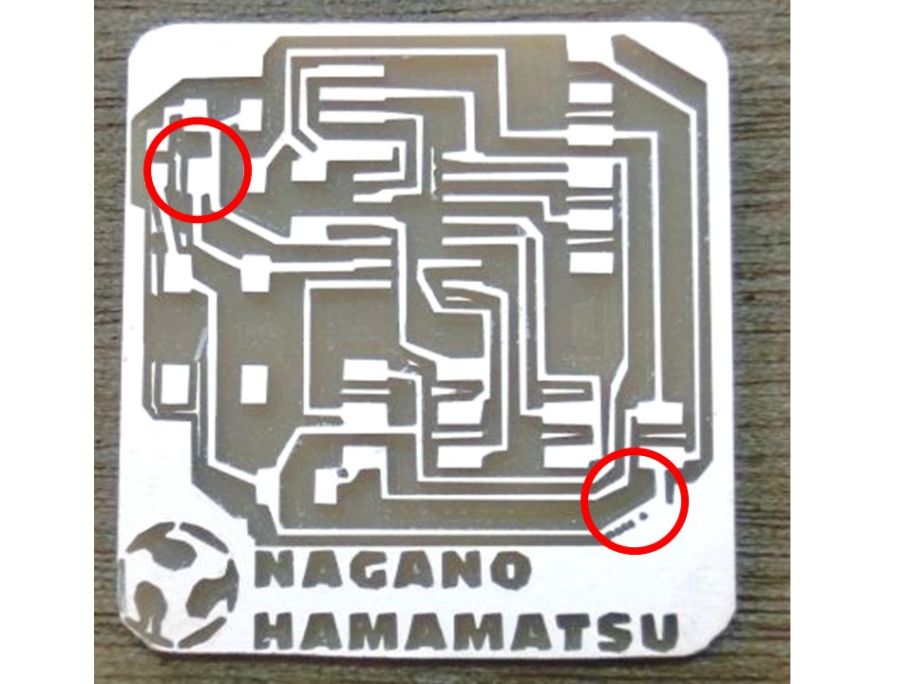
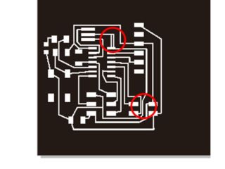
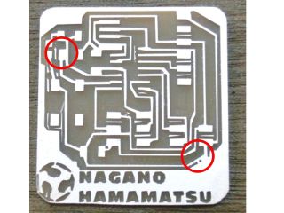
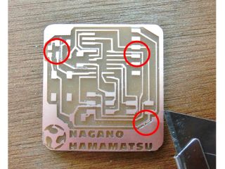
After confirming the board after cutting, a part where the pattern was connected was found. Corrected using a cutter.
 4. assembly
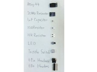
Select the necessary parts and pasted on paper.
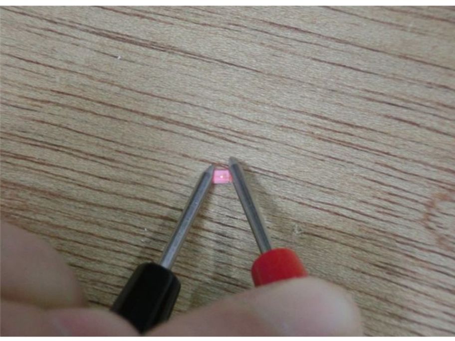
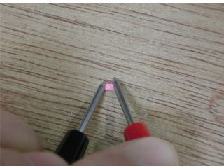
I soldered in order.The polarity of the LED was checked with a circuit meter.
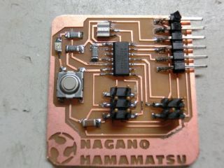
This is a completed bord.
 Archive
-
Eagle data (sch,brd,Eagle)
-
Pattern image (png)
-
Board image (png)
-
Eagle data (rml,fabmodules)
This week's assignment is over.